X9S-PB1000THE PROXBADGE COMMUNICATES W/THE BEACON & SENSORS
Proxense LLC
Click to zoom
Application Details
- Equipment Class
- DTS - Digital Transmission System
- Date of Grant
- Jan 20, 2011
- Application Purpose
- Original Equipment
- Date of Application
- Jan 19, 2011
- Equipment Note
- THE PROXBADGE COMMUNICATES W/THE BEACON & SENSORS
- Frequency Range
- 2405.00000000 - 2480.00000000
- Company
- Proxense LLC
- Country
- United States
Documents & Files
Document Text
Text extracted from the exhibit documents filed with the FCC. Open a document above to read the original.
Users Manual
Note: Instal llation must b Pro be performed oxBad by a Proxens dge In se authorized nstalla professional ation installer. Guidde MODEL NUMBER: PB1000 Page i MODEL NUMBER: PB1000 INSTALLATION: This product MUST be installed by a Proxense authorized professional installer. FCC STATEMENTS: THIS DEVICE COMPLIES WITH PART 15 OF THE FCC RULES. OPERATION IS SUBJECT TO THE FOLLOWING TWO CONDITIONS: (1) THIS DEVICE MAY NOT CAUSE HARMFUL INTERFERENCE, AND (2) THIS DEVICE MUST ACCEPT ANY INTERFERENCE RECEIVED, INCLUDING INTERFERENCE THAT MAY CAUSE UNDESIRED OPERATION. THE MANUFACTURER IS NOT RESPONSIBLE FOR ANY RADIO OR TV INTERFERENCE CAUSED BY UNAUTHORIZED MODIFICATIONS TO THIS EQUIPMENT. SUCH MODIFICATIONS COULD VOID THE USER’S AUTHORITY TO OPERATE THE EQUIPMENT. © 2010 Proxense, LLC. All rights reserved. Proxense, the Proxense logo, and other Proxense marks are owned by Proxense, LLC and may be registered. All other trademarks are the property of their respective owners. Proxense assumes no responsibility for any errors that may appear in this guide. Information contained herein is subject to change without notice. Corporate Office: Proxense, LLC 689 NW Stonepine Drive Bend, OR 97701 541.382.5745 DOCUMENT NUMBER: PX-9000-0000-00 Revision Log: This log identifies those portions of this document, which have been revised since the initial release and the date of each revision. Date Version Revisions 08/16/10 00 Initial Release ProxBadge Installation Guide MODEL NUMBER: PB1000 Page 2 Introduction This Installation Guide is written for a Proxense authorized installation professional. Only a Proxense authorized installation professional may configure and provisioning this product. There are three steps to the installation: • Before you start • Configuring the ProxBadge • Provisioning the ProxBadge Step 1: Before you start To ensure that you have the most recent version of this guide, be sure to check our FTP site before you start the installation. Package Contents Your package includes the following items: • This Guide (Your package maybe part of a master pack where only one copy of this guide will be provided.) • One ProxBadge • One USB 2.0 cable, Type A to Micro-B Minimum Requirements • ProxNet installation site survey which lists the following: a. User information b. Authorized applications for user c. Authorized workstations for user ProxB MODE Ste a. P b. R c. C u p e. S S u b W s b Badge Installa EL NUMBER p 2: Con ress the pow Run the ProxA Click the Add user. Enter a period, and P Select the Au Select the au user by using buttons. Clic When the En screen appea button. ation Guide : PB1000 nfigurin er button. Ve Admin executa d User button all user inform Prox tag ID nu uthorized wo thorized work g the Add and k the OK butt rollment fina ars click the C g the Pr erify that the g able from eith n to add a new mation, grace umber. orkstations ta kstations for t d Remove ton. alized dialog Close window roxBadg green LED (p her a network w d. S th th ab. he w f. R S b d b ge ower LED) is share or loc a Select the Aut he authorized he Add and R Reselect user Select the fing button. Follow dialog box. C button. s flashing. al drive of the thorized app d applications Remove butto and click the ger to enroll a w the instructi lick the Fina l P e client. plications tab for the user b ons. e Enroll User nd press the ons in the St a lize enrollme Page 3 b. Select by using rbutton. Start tatus ent ProxBadge Installation Guide MODEL NUMBER: PB1000 Page 4 Step 3: Provisioning the ProxBadge Please contact the system administrator who must now provision the ProxBadge. If you need technical assistance Telephone: 561.798.6166 Email: [email protected]
Cover Letter(s)
August 16th, 2010 Federal Communications Commission Authorization and Evaluation Division Confidentiality Request regarding application for certification – Product Name: ProxBadge Model No: PB1000 P/N: PX-7100-0000-00 FCC ID: X9S-PB1000 Pursuant to Sections 0.457 and 0.459 of the Commission’s Rules, we hereby request long term confidential treatment of information accompanying this application as listed below: 1. Schematic Diagram PB1000 (P5) – Schematic_FCC_1.0.pdf 2. Parts List PB1000 (P5) – Parts List_FCC_1.0.pdf 3. Block Diagram PB1000 (P5) – Block Diagram_FCC_1.0.pdf 4. Theory of Operation PB1000 (P5) – Theory of Operation_FCC_1.0.pdf The above documents contain trade secrets and proprietary information not customarily released to the public. The public disclosure of these documents may be harmful to the applicant and provide unjustified benefits to its competitors. The applicant understands that pursuant to Section 0.457 of the rules, disclosure of this application and all accompanying documentation will not be made before the date of the Grant for this application. Further, the applicant understands that the documents listed above as requiring long term confidential treatment will remain undisclosed indefinitely. Sincerely, Wayne Becker Sr. Engineer Proxense, LLC Florida Office (Engineering): 1013 N State Road 7 Royal Palm Beach, FL 33411 561.798.6166 Ext 124
External Photos
Product Name: ProxBadgeModel No: PB1000P/N: PX-7100-0000-00HW Build: P5FCC ID: X9S-PB1000 External Photos Proxense, LLC Front Rear Sides USB 2.0 Micro-B Jack Production SWF RF switch connector exposed (plastic housing drilled) for conducted measurements. Page 1 of 1Rev 1.0
ID Label/Location Info
FCC ID Label Artwor k & Label Location Proxense, LLC Scale: 1:1 Page 1 of 1Rev 1.0 5V xxxmA S/N: 1234567890123456789 PROXENSE Model No: PB1000 P/N: PX-7100-0000-00 L/C: ZZZZZZ-ZZ Made in the USA FCC ID: X9S-PB1000 IC: 9282A-PB1000 12345678901234567890 EZZZZZZ Product Name: ProxBadgeModel No: PB1000P/N: PX-7100-0000-00HW Build: P5FCC ID: X9S-PB1000 Dimensions: 1.25” x 0.5” RC 0.060”
Internal Photos
Internal Photos Proxense, LLC Front Page 1 of 1Rev 1.0 Rear Product Name: ProxBadgeModel No: PB1000P/N: PX-7100-0000-00HW Build: P5FCC ID: X9S-PB1000
Operational Description
DESIGN ADVANTAGES Best in Class Performance—Smallest Occupied Volume • Powerful combination of 81% peak efficiency and simple implementation guidelines. • Minimal ground clearance and component “keep out” areas. Very low component height. • High selectivity eliminates the cost for additional filters and frees up board space High Tolerance to Frequency Shifts • IMD’s high RF isolation resists antenna detuning that otherwise can impair reception. • Single part works for various PCB sizes and layouts. Quicker Time-to-Market • Fewer design modifications required to pass RF test suite. • Simpler implementation—no matching networks. RoHS Compliant • Antennas comply with appropriate RoHS Directives. SERVICE AND SUPPORT Extensive RF Experience • Our Savvi ceramic antennas are supported by exten- sive application notes, and when needed, by the expertise of RF engineers who have integrated hundreds of antenna designs into wireless devices. Global Operations & Design Support • Ethertronics’ global operations encompass an integrated network of design centers that provide local customer support. Ethertronics’ Savvi series of Isolated Magnetic Dipole™ (IMD) antennas deliver on the key needs of device designers for higher functionality and performance in smaller/thinner designs. These innovative antennas provide compelling advantages for Bluetooth enabled cell phones, media players and other mobile devices. PRODUCT: BLUETOOTH ® Savvi TM Embedded Bluetooth Antennas 2.4—2.5 GHz END USER ADVANTAGES Superior Range • Greater antenna efficiency means longer range and a better end user experience. Exceptional Coverage • Better coverage delivers more reliable wireless connections for mobile phones, laptops, stereo headsets, cars, media players, audio systems and more. ETHERTRONICS 9605 Scranton Road, Suite 300 | San Diego, CA 92121 - USA | www.ethertronics.com tel +(1) 858.550.3820 | fax +(1) 858.550.3821 | contact: [email protected] TECHNOLOGY ADVANTAGES KEY BENEFITS Part No. M830310 Real-World Performance and Implementation Ceramic antennas may look alike on the outside, but the important difference is inside. Other antennas may contain simple PiFA or monopole designs that interact with their surroundings, complicating layout or changing performance with use position. Ethertronics’ antennas utilize patented IMD technology to deliver a unique size and performance combination. Stays in Tune High RF isolation means IMD antennas resist de- tuning regardless of usage position. And one standardized part can typically be placed in a variety of locations. Smallest Effective Size IMD antennas require a smaller keep-out area for surrounding components, leading to a smaller effective size. High Performance IMD’s high efficiency and simple design rules lower development risk and speed time-to-market without sacrificing performance. Plus, high RF selectivity eliminates the cost and space for band-pass circuitry. More information is available on our Website at www.ethertronics.com/resources/. Ethertronics’ Savvi TM Bluetooth Embedded Antenna Specifications Ethertronics produces a wide variety of standard and custom antennas to meet user needs. Below are the typical specs for a Bluetooth application. PRODUCT: Bluetooth ® Antenna Electrical Specifications Typical Characteristics (inside an enclosure) Size 8x3x1.3mm Mounting Surface mount Packaging Tape & Reel Mechanical Specifications Typical Efficiency, Return Loss Antenna Radiation Patterns Typical Performance Ethertronics’ Test Board PCB: 40x80mm BT Antenna 2.4—2.5 GHz Peak Gain 1.39 dBi Average Efficiency 78% VSWR Match 2.0:1 max Feed Point Impedance 50 ohms unbalanced Power Handling .5 Watt cw Polarization Linear 2.4 GHz Band Phi = 0 o Plane Theta = 90 o Plane Phi = 90 o Plane © 2009 Ethertronics. All rights reserved. Ethertronics, the Ethertronics logo, shaping antenna technology, Savvi, Isolated Magnetic Dipole and the iMD logo are trademarks of Ethertronics. All other trademarks are the property of their respective owners. Specifications subject to change and are dependent upon actual implementation. BT 03/27/09 z x z y x y
Operational Description
Integrated Omni (x2) RX / TX ANT1 ANT2 Antenna Technical Description Page 1 of 3Rev 1.1 Proxense, LLC Micro USB-B Product Name: ProxBadgeModel No: PB1000P/N: PX-7100-0000-00HW Build: P5FCC ID: X9S-PB1000
Test Report
FCC PART 15.247 AND IC RSS-210 TEST REPORT DIGITAL SPREAD SPECTRUM Applicant PROXENSE, LLC. Address 1013 N. State Road 7 Royal Palm Beach, Fl. 33411 USA FCC ID X9S-PB1000 IC 9282A-PB1000 Model Number PB1000 Product Description Badge Date Sample Received 7/29/2010 Date Tested 7/29/2010 Tested By Richard Block Approved By Mario R. de Aranzeta Report Number 1795AT10TestReport.doc Test Results PASS FAIL THE ATTACHED REPORT SHALL NOT BE REPRODUCED EXCEPT IN FULL WITHOUT THE WRITTEN APPROVAL OF TIMCO ENGINEERING, INC. 849 NW State Road 45 Newberry, FL 32669 USA Ph: 888.472.2424 or 352.472.5500 Fax: 352.472.2030 Email: [email protected] Website: www.timcoengr.com Testing Certificate # 0955-01 APPLICANT: PROXENSE, LLC. FCC ID: X9S-PB1000 IC: 9828A-PB1000 REPORT: P\PROXENSE\1795AT10\1795AT10TestReport.doc Page 2 of 27 Mdea 3.14.2008 TABLE OF CONTENT GENERAL REMARKS ............................................................................................................................... 3 GENERAL INFORMATION ........................................................................................................................ 4 EMC EQUIPMENT LIST............................................................................................................................ 5 TEST PROCEDURES ................................................................................................................................ 6 CALCULATION OF DUTY CYCLE ............................................................................................................. 7 RADIATION INTERFERENCE ................................................................................................................. 10 POWER LINE CONDUCTED INTERFERENCE ........................................................................................ 13 OCCUPIED BANDWIDTH ....................................................................................................................... 16 POWER OUTPUT .................................................................................................................................... 18 SPURIOUS EMISSIONS AT ANTENNA TERMINALS ............................................................................... 19 RADIATED SPURIOUS EMISSIONS INTO ADJACENT RESTRICTED BAND .......................................... 21 POWER SPECTRAL DENSITY ................................................................................................................ 25 RADIATED EMISSIONS TEST SETUP PHOTO ....................................................................................... 26 POWERLINE CONDUCTED TEST SETUP PHOTO .................................................................................. 27 APPLICANT: PROXENSE, LLC. FCC ID: X9S-PB1000 IC: 9828A-PB1000 REPORT: P\PROXENSE\1795AT10\1795AT10TestReport.doc Page 3 of 27 Mdea 3.14.2008 GENERAL REMARKS The attached report shall not be reproduced except in full without the written permission of Timco Engineering Inc. The test results relate only to the items tested. Summary The device under test does: fulfill the general approval requirements as identified in this test report not fulfill the general approval requirements as identified in this test report Attestations This equipment has been tested in accordance with the standards identified in this test report. To the best of my knowledge and belief, these tests were performed using the measurement procedures described in this report. All instrumentation and accessories used to test products for compliance to the indicated standards are calibrated regularly in accordance with ISO 17025 requirements. Testing Certificate # 0955-01 I attest that the necessary measurements were made, under my supervision, at: Timco Engineering Inc. 849 NW State Road 45 Newberry, Fl 32669 Authorized Signatory Name: Mario de Aranzeta C.E.T. Compliance Engineer/ Lab. Supervisor Date: 11/16/2010 APPLICANT: PROXENSE, LLC. FCC ID: X9S-PB1000 IC: 9828A-PB1000 REPORT: P\PROXENSE\1795AT10\1795AT10TestReport.doc Page 4 of 27 Mdea 3.14.2008 GENERAL INFORMATION DUT Specification Applicable Standard Part 15.247, RSS-210, RSS-GEN DUT Description Badge FCC ID X9S-PB1000 IC 9282A-PB1000 Operating Frequency TX: 2405-2480 MHz DUT Power Source 110–120Vac/50– 60Hz DC Power Battery Operated Exclusively Test Item Prototype Pre-Production Production Type of Equipment Fixed Mobile Portable Antenna Connector N/A Antenna internal Test Facility Timco Engineering Inc. located at 849 NW State Road 45 Newberry, FL 32669 USA. Test Conditions Temperature: 26ºC Relative humidity: 50% Test Exercise The DUT was placed in continuous transmit mode of operation. Test Supporting Equipment Supporting Device Manufacturer Model / FCC ID Serial Number Laptop Dell Inspiron 6000 Service Tag HDXH191 APPLICANT: PROXENSE, LLC. FCC ID: X9S-PB1000 IC: 9828A-PB1000 REPORT: P\PROXENSE\1795AT10\1795AT10TestReport.doc Page 5 of 27 Mdea 3.14.2008 EMC EQUIPMENT LIST Device Manufacturer Model Serial Number Cal/Char Date Due Date 3-Meter Semi- Anechoic Chamber Panashield N/A N/A Listed 3/10/10 3/10/12 AC Voltmeter HP 400FL 2213A14499 CAL 3/23/09 3/23/11 Antenna: Dipole Kit Electro- Metrics TDA-30/1-4 153 CHAR 6/10/09 6/10/11 Frequency Counter HP 5385A 3242A07460 CAL 5/26/09 5/26/11 Hygro- Thermometer Extech 445703 0602 CAL 1/30/09 1/30/11 Modulation Analyzer HP 8901A 3435A06868 CAL 5/26/09 5/26/11 Digital Multimeter Fluke FLUKE-77-3 79510405 CAL 5/18/09 5/18/11 Analyzer Tan Tower Preamplifier HP 8449B-H02 3008A00372 CAL 11/21/09 11/21/11 Analyzer Tan Tower Quasi- Peak Adapter HP 85650A 3303A01690 CAL 11/22/09 11/22/11 Analyzer Tan Tower RF Preselector HP 85685A 3221A01400 CAL 11/21/09 11/21/11 Analyzer Tan Tower Spectrum Analyzer HP 8566B Opt 462 3138A07786 3144A20661 CAL 11/24/09 11/24/11 Temperature Chamber Tenney Engineering TTRC 11717-7 CHAR 4/25/10 4/25/12 APPLICANT: PROXENSE, LLC. FCC ID: X9S-PB1000 IC: 9828A-PB1000 REPORT: P\PROXENSE\1795AT10\1795AT10TestReport…
Text truncated - open the document above for the full version.
Test Setup Photos
APPLICANT: PROXENSE, LLC. FCC ID: X9S-PB1000 TEST SET UP PHOTOS
Contact Information
Applicant
Wayne Becker(Senior Engineer)
Test Firm
Timco Engineering, Inc.Bruno Clavier
Technical Specifications
| # | Rule Parts | Frequency Range | Power Output |
|---|---|---|---|
| 1 | 15C | 2.40 GHz - 2.48 GHz | 1.00 mW |
Other Applications from Proxense LLC
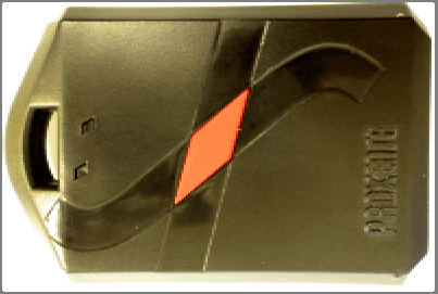
X9S-PT1000
Jan 20, 2011THE PROXTAG COMMUNICATES W/THE BEACON & SENSORS
Equipment Class
DTS - Digital Transmission System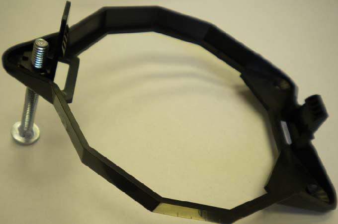
X9S-BE1000
Jan 20, 2011THE BEACON IS THE PROXNET SYSTEM COORDINATOR
Equipment Class
DTS - Digital Transmission System
X9S-BS1000
Jan 20, 2011THE BIOSENSOR COMMUNICATES W/THE BEACON & PROX DEV
Equipment Class
DTS - Digital Transmission System
X9S-AS1000
Jan 20, 2011THE AREASENSOR COMMUNICATED W/THE BEACON & PROX DEVS
Equipment Class
DTS - Digital Transmission System