XBAZW120Door/Window Sensor Gen5
Aeon Labs LLC.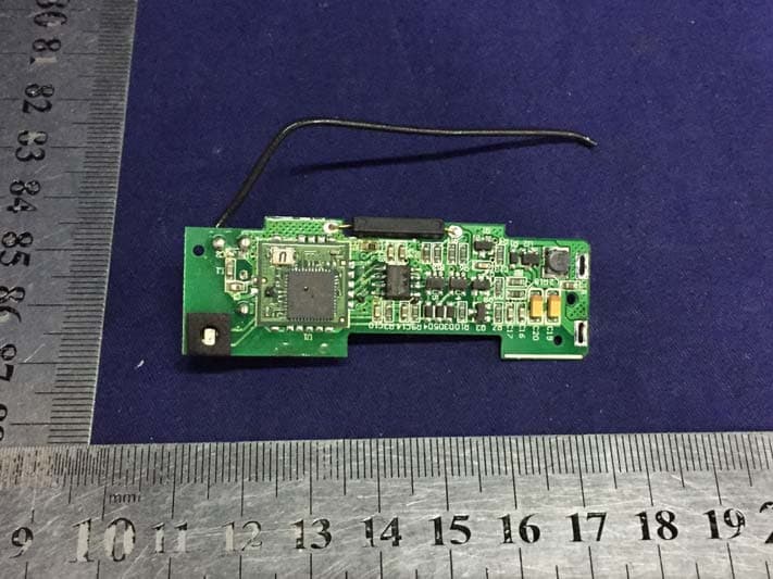
Click to zoom
Application Details
- Equipment Class
- DXT - Part 15 Low Power Transceiver, Rx Verified
- Date of Grant
- Nov 30, 2015
- Application Purpose
- Original Equipment
- Date of Application
- Nov 30, 2015
- Equipment Note
- Door/Window Sensor Gen5
- Frequency Range
- 908.40000000 - 908.42000000
- Company
- Aeon Labs LLC.
- Country
- United States
Documents & Files
Document Text
Text extracted from the exhibit documents filed with the FCC. Open a document above to read the original.
Users Manual
View the expanded manual: http://aeotec.com/support Aeotec by Aeon Labs Door/Window Sensor. 1 3 The Aeotec by Aeon Labs Door/Window Sensor Gen5 provides your Z-Wave network with the intelligence required for a modern home automation and security system. And it does it all in a smaller, more elegant design crafted to suit any home's decor. The Door Window Sensor is also a security Z-wave device that supports Over The Air (OTA) for firmware updates. The installation of your Door Window Sensor has two major steps: the Main Sensor and the Magnet. Your Door Window Sensor will use wireless technology to talk to your Z-Wave network once paired to your Z-Wave network. Selecting where you'll place your Door/Window Sensor in your home is just as important as the actual affixing it to the surface. Whether it’s for security or intelligence purposes, your sensor: With your mounting plates prepared to hold each component of your sensor, it’s time to add it to your Z-Wave network. With your sensor added to your Z-Wave network, it's now time to insert each main part of your sensor into the corresponding sensor plate. 1. 2. 3. 4. Should be affixed indoors and away from sources of moisture. Placed within 30 meters of another Z-Wave device that is either a gateway or not powered by batteries. The magnet and the main sensor must be less than 2cm apart. Main sensor must be affixed to the door or window and the magnet must be affixed to the frame. The magnet and the main sensor must separate when the door or window is opened. Should not be mounted on a metal frame. Affix your Sensor plates to a surface. The Mounting plates can be affixed using screws or double- sided tape. If you are using screws, attach both mounting plates to the respective surface using the two 20mm screws provided. If you are using double-sided tape, wipe the two surfaces clean of any oil or dust with a damp towel. When the surface has completely dried, peel one side of the tape back and attach it to the corresponding section on the rear side of the mounting plates. Familiarize yourself with your Door/Window Sensor. Quick start. With your Door Window Sensor now working as a part of your smart home, you’ll be able to configure it from your home control software or phone application. Please refer to your software’s user guide for precise instructions on configuring Door Window Sensor to your needs. LEDLatch Button Screw HolesHitchHitch Hole Orientation Dimples Magnet Unit Action Button Security Tamper Switch Battery Holder Double-Sided Mounting Tape Sticking Area Magnet Unit Outer Sehll Security Tamper Switch Hole Adding your Sensor to your Z-Wave network . Attach your sensor to its plates. Package contents: 1. Sensor Unit. 2. Bidirectional Mount Plate. 3. Magnet Unit. 4. Magnet Unit Outer Shell. 5. AAA Batteries(×2). 6. Double-Sided Mounting Tape(×6). 7. Screws(×4). 1236754 2 1. 2. 3. 4. 1. 2. Let your Z-Wave primary controller/gateway enter into adding/inclusion mode. Take your Sensor near to your primary controller. Press the Action Button once on your Sensor. If your Door Window Sensor has been successfully added to your Z-Wave network, its Status LED will fast blink for 2 seconds and then be solid for 2 seconds when you press the Action Button again. If the adding was unsuccessful and the Status LED continues to fast blink for 8 seconds and then slow blink for 3 seconds, repeat the above steps. Insert the larger of your two sensor parts into the large mounting plate ensuring that the dlmple on the front is on the same side as the smaller mounting plate. lnsert the smaller of your two sensor parts into its mounting plate. GEN5 1. 2. Remove your Sensor unit from its Back Mounting Plate, press the Action Button on the back of the Sensor unit and then release the Action Button. This will trigger and send a wake up notification command to your controller/gateway. If you want your Sensor to keep awake for a longer time, press and hold the Action Button on the back of the Sensor unit for 3 seconds, then your Sensor will wake up for 10 minutes and the Status LED will fast blink while it is awake. 4 In order to send your Sensor new configuration commands from your Z-Wave controller or gateway, it will need to be woken up. Your sensor can be removed from your Z-Wave network at any time. You'll need to use your Z-Wave network's main controller/ Send a wake up notification. Removing your Sensor from your Z-Wave network. Advanced functions. 1. 2. 3. 4. Put your primary controller into device removal mode. Unlock your Sensor from the Back Mount plate and take the Sensor unit near to your primary controller. Press the Action Button on your Sensor. If your Door Window Sensor has been successfully removed from your Z-Wave network, its Status LED will fast blink for 8 seconds and then slow blink for 3 seconds when you press the Action Button again. If the removing was unsuccessful, the Status LED will fast blink for 2 seconds and then be solid for 2 seconds when you press the Action Button, repeat the above steps. If you want your Sensor as a non-security device in your Z-wave network, you just need to press the Action Button once on Door Window Sensor when you use a controller/gateway to add/ include your Sensor. Security or Non-security feature of your Sensor in Z-wave network. Factory Reset your Sensor. Including Door/Window Sensor as a non-secure device: Model number: ZW120. Battery: Up to 1 year battery life with 2×AAA batteries. Operating temperature: 0°C to 40°C. Relative humidity: 8% to 80%. Operating distance: Up to 300 feet/100 metres outdoors. Technical specifications. 5 In order to take full advantage of all functionality the Door Window Sensor, you may want your Sensor is a security device that uses secure/encrypted message to communicate in Z-wave network, so a security enabled controller/gateway is needed for the Door Window Sensor to be used as a security device. Including Door/Window Sensor as a secure device: Warranty. Aeon Labs warran…
Text truncated - open the document above for the full version.
Cover Letter(s)
RF_160, Issue 03 Declaration of Authorization We Name: Aeon Labs LLC. Address: 121 Buckingham Drive Unit 36 Santa Claras, CA City: Santa Claras, CA Country: United States Declare that: Name Representative of agent: Lisa Wang (1) Agent Company name: EMTEK (SHENZHEN) CO., LTD. Address: Bldg 69, Majialong Industry Zone, Nanshan District, City: Shenzhen Country China is authorized to apply for Certification of the following product(s): Product description: Door/Window Sensor Gen5 Type designation: ZW120-A Trademark: N/A on our behalf. Date: 2015-11-27 City: Santa Claras Name: William Li Function: Director of Business Development Signature: Notes: (1): Required for FCC application (2): For FCC it must be the Grantee Code “owner” or the authorized agent.
Cover Letter(s)
FCC, Request for non-disclosure Date: 16-Jul-10 RF_501, Issue 6 Page 1 of 1 Company Name: Aeon Labs LLC. Address : 121 Buckingham Drive Unit 36, Santa Claras, CA City: Santa Claras Country: United States To: Telefication B.V., Dept. FCC TCB Edisonstraat 12A 6902 PK ZEVENAAR The Netherlands Subject: Request for confidentiality FCC ID: XBAZW120 Reference number: ###### Dear FCC TCB, 1. Long-Term Confidentiality Pursuant to 47 CFR Section 0.459(a) & (b), we hereby requests non-disclosure and confidential treatment of the following materials submitted in support of FCC certification application: Bill(s) of Material Block Diagrams Operational Description Schematic Diagrams Tune-up Procedure Above materials contain secrets, proprietary and technical information, which would customarily be guarded from competitors under 47 CFR, section 0.457(d)(2). Disclosure or publication or any portion of this company confidential material to other parties could cause substantial competitive harm and provide unjustified benefits for competitors. 2. Short-Term Confidentiality (STC) Pursuant to Public Notice DA 04-1705 of the Commission’s policy, in order to comply with the marketing regulations in 47 CFR §2.803 and the importation rules in 47 CFR §2.1204, a pplicant hereby requests Short-Term Confidential treatment of the following materials (note 1): Internal Photos User’s Manual Test Set-up Photos External Photos Justification: Planned Release Date STC: (notes 2, 3, 4, 5) Date: November 27, 2015 Name and signature of applicant: Notes: 1) A document or type of document can only have ONE type of confidentiality! 2) Short-Term confidentiality is in principle for 45 days from date of grant; it can be extended max 3 times (total time 180 days max.)! 3) FCC must be informed when marketing begins earlier. 4) Release takes place automatically thus extension must be requested in time. Telefication does not remind you of this! 5) Request for extension or for release must be received by Telefication at least 7 days before date of actual marketing or before expiration of the STC period
External Photos
External Photos
ID Label/Location Info
Label& Location
Internal Photos
Internal Photos Z-wave Module Antenna
Test Report
TRF No:FCC 15.249/A Page 1 of 31 Report No: ES151027019E Access to the World ELECTROMAGNETIC EMISSIONS COMPLIANCE REPORT INTENTIONAL RADIATOR CERTIFICATION TO FCC CFR47 PART 15 Section 15.249 REQUIREMENT OF Product Name: Door/Window Sensor Gen5 MODEL No.: ZW120-A Trademark: N/A FCC ID: XBAZW120 REPORT NO: ES151027019E ISSUE DATE: November 12, 2015 Prepared for Aeon Labs LLC. 121 Buckingham Drive Unit 36, Santa Claras, CA, United States Prepared by EMTEK (Shenzhen) Co., Ltd. Bldg 69, Majialong Industry Zone, Nanshan District, Shenzhen, Guangdong, China TEL: 86-755-26954280 FAX: 86-755-26954282 TRF No:FCC 15.249/A Page 2 of 31 Report No: ES151027019E Access to the World VERIFICATION OF COMPLIANCE Applicant: Aeon Labs LLC. 121 Buckingham Drive Unit 36, Santa Claras, CA, United States Manufacturer: Fantem Technologies (Shenzhen) Co., Ltd North,3/F, Yitoa Technology Industrial Park, Baihua Yuan Rd., The Second Industrial Area, Guangming Sub-district Office, Guangming New District, Shenzhen, Guangdong, China Product Description: Door/Window Sensor Gen5 Model Number: ZW120-A Date of Test: October 28, 2015 to November 12, 2015 We hereby certify that: The above equipment was tested by EMTEK (Shenzhen) Co., Ltd. The test data, data evaluation, test procedures, and equipment configurations shown in this report were made in accordance with the procedures given in ANSI C63.10 (2013) and the energy emitted by the sample EUT tested as described in this report is in compliance with conducted and radiated emission limits of FCC Rules Part 15.249. The test results of this report relate only to the tested sample identified in this report. Date of Test : October 28, 2015 to November 12, 2015 Prepared by : Yaping Shen/Editor Reviewer : Joe Xia/Supervisor Approve & Authorized Signer : Lisa Wang/Manager TRF No:FCC 15.249/A Page 3 of 31 Report No: ES151027019E Access to the World Table of Contents 1. GENERAL INFORMATION .................................................................................................................... 4 1.1. PRODUCT DESCRIPTION ..................................................................................................................... 4 1.2. RELATED SUBMITTAL(S) / GRANT (S) ................................................................................................ 5 1.3. TEST METHODOLOGY .......................................................................................................................... 5 1.4. SPECIAL ACCESSORIES ...................................................................................................................... 5 1.5. EQUIPMENT MODIFICATIONS ............................................................................................................. 5 1.6. MEASUREMENT UNCERTAINTY .......................................................................................................... 6 1.7. TEST FACILITY ....................................................................................................................................... 6 2. SYSTEM TEST CONFIGURATION ........................................................................................................ 7 2.1. EUT CONFIGURATION .......................................................................................................................... 7 2.2. EUT EXERCISE ...................................................................................................................................... 7 2.3. TEST PROCEDURE ............................................................................................................................... 7 2.4. DESCRIPTION OF TEST MODES ......................................................................................................... 7 3. SUMMARY OF TEST RESULTS ............................................................................................................ 8 4. RADIATED EMISSION TEST ................................................................................................................. 9 4.1. MEASUREMENT PROCEDURE ............................................................................................................ 9 4.2. TEST SET-UP (BLOCK DIAGRAM OF CONFIGURATION) ................................................................ 10 5.3 MEASUREMENT EQUIPMENT USED: ................................................................................................ 11 5.4 RADIATED EMISSION LIMIT ............................................................................................................... 11 5.5 MEASUREMENT RESULT ................................................................................................................... 13 5. PERIODIC OPERATION ....................................................................................................................... 20 6. BANDWIDTH TEST .............................................................................................................................. 21 6.1. MEASUREMENT PROCEDURE .......................................................................................................... 21 6.2. TEST SET-UP (BLOCK DIAGRAM OF CONFIGURATION) ................................................................ 21 6.3. MEASUREMENT EQUIPMENT USED: ................................................................................................ 21 6.4. MEASUREMENT RESULTS: ................................................................................................................ 21 7. BAND EDGE TEST ............................................................................................................................... 22 7.1. MEASUREMENT PROCEDURE .......................................................................................................... 22 7.2. TEST SET-UP (BLOCK DIAGRAM OF CONFIGURATION) ................................................................ 22 7.3. MEASUREMENT EQUIPMENT USED:…
Text truncated - open the document above for the full version.
Test Setup Photos
Setup photos RADIATED EMISSION TEST Radiated Emission (9KHz-30MHz) Radiated Emission (30MHz-1GHz) Radiated Emission (1GHz-10GHz)
Contact Information
Applicant
William Li(Director of Business Development)
Technical Contact
EMTEK (SHENZHEN) CO., LTD.David Lee
[email protected]86 755 26504659
Bldg 69,Majialong Industry Zone,Nanshan District · China
Non-Technical Contact
EMTEK (SHENZHEN) CO., LTD.Lisa Wang
[email protected]86 755 26504659
Test Firm
EMTEK (Shenzhen) Co., Ltd.David Lee
Technical Specifications
| # | Rule Parts | Frequency Range | Power Output |
|---|---|---|---|
| 1 | 15C | 908.4 MHz - 908.42 MHz | - |
Other Applications from Aeon Labs LLC.
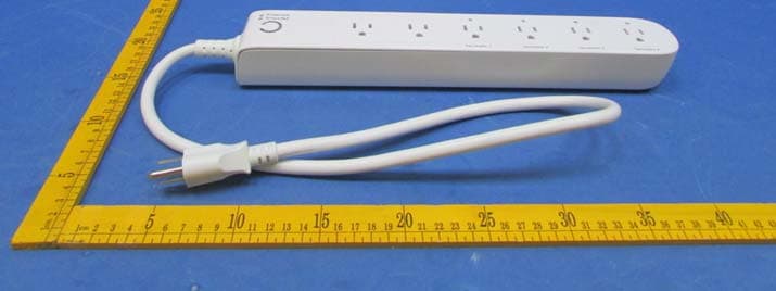
XBAZW069
Jan 25, 2016Smart Strip Gen5,Strip Gen5
Equipment Class
DXT - Part 15 Low Power Transceiver, Rx Verified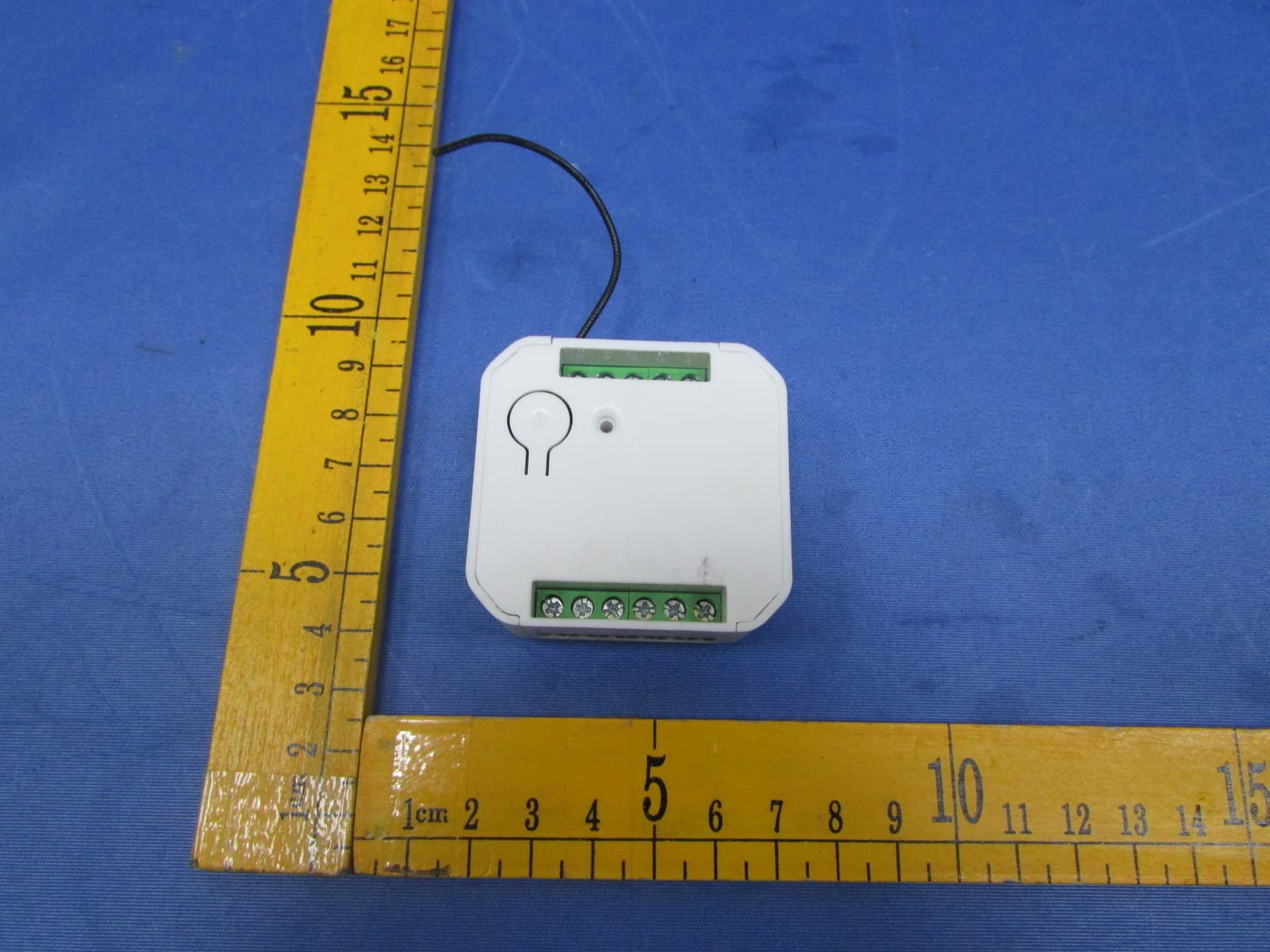
XBADSC14104
Dec 28, 2015DSC17103-ZWUS,DSC14104-ZWUS
Equipment Class
DXT - Part 15 Low Power Transceiver, Rx Verified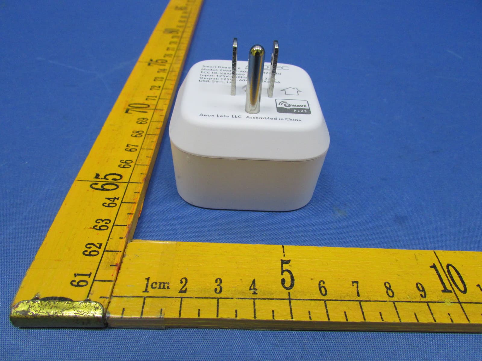
XBAFT099
Dec 23, 2015Smart Dimmer 6,Dimmer,Dimmer 6
Equipment Class
DXT - Part 15 Low Power Transceiver, Rx Verified
XBAZW056
May 21, 2015Doorbell Gen5
Equipment Class
DXT - Part 15 Low Power Transceiver, Rx Verified
XBAZW056SENSOR
May 20, 2015Doorbell Gen5(Garage Sensor)
Equipment Class
DSC - Part 15 Security/Remote Control Transmitter