XBYFKT05ZAPhottix Odin TTL Trigger for Canon
Shenzhen Fudasi Technology Co., Ltd.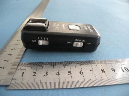
Click to zoom
Application Details
- Equipment Class
- DXX - Part 15 Low Power Communication Device Transmitter
- Date of Grant
- May 31, 2011
- Application Purpose
- Original Equipment
- Date of Application
- May 30, 2011
- Equipment Note
- Phottix Odin TTL Trigger for Canon
- Frequency Range
- 2467.00000000 - 2473.00000000
- Country
- China
Documents & Files
Document Text
Text extracted from the exhibit documents filed with the FCC. Open a document above to read the original.
Users Manual
Phottix Odin TTL Trigger for Canon Parts Transmitter Control Unit (TCU) 1. LCD Screen 2. Options Button 3. Mode Button 4. Zoom Button 5. Power Button 6. LED 7. + / - / Selection Buttons 8. Test Button 9. Clear Button 10. High Speed Sync / Second Curtain Sync Button 11. LCD Backlight Button 12. USB Port 13. Battery Compartment 14. Locking Ring 15. Hot Shoe Please Note: After adding turning on the Phottix Odin TCU and receivers you must take one photograph for the TCU to “learn” about your camera and flashes. The first shot you take will not be properly exposed. Subsequent images will be correct. Slave mode does not need to be set on flashes on Phottix Odin receivers. Many TTL flashes have been tested but the manufacturer cannot guarantee that all third party TTL flashes will function properly with the Phottix Odin. It has been designed and optimized for original Canon flashes using the ETTL II system. Tip: Turn off all devices – flashes/strobes, cameras, and the Phottix Odin TCU and receivers - when connecting and disconnecting devices. Upgrading firmware by USB The firmware of the TCU and receivers can be upgraded using the included USB cable. Any upgrades and full instructions will be announced on the Phottix Blog (journal.phottix.com). LED functions The LED on the TCU and receiver units will turn green when the camera is focusing and red when a photo is being taken. Inserting batteries 1. Press the battery cover in while pushing it away from the Phottix Odin TCU or receiver. The battery cover will slide open. 2. Remove the battery cover. 3. Insert AA batteries as shown. 4. Replace the battery cover and push back into the locked position. 5. When the battery power icon on the TCU shows low battery levels change the batteries. 6. When the power is very low, the LED will flash red light every 2 seconds. Turning the TCU and receiver on/off 1. To turn on the Phottix Odin TCU: Press and hold the Power Button until an image appears on the LCD screen. To turn off: Press and hold the Power Button until the LCD screen goes blank. 2. To turn on the Phottix Odin receiver: Move the power switch to the “ON” position. Turn off the receiver by moving the power switch to the “OFF” position. Groups and Channels 1. The Phottix Odin System has 3 groups: A, B, and C, and 4 tranmission channels: 1, 2, 3, 4. 2. Receivers can be assigned both group and channel designations. 3. The transmitter will allow power levels and changes to be set for each group. Unless turned off on the TCU, all receivers set to the same channel and group will fire. The TCU Connecting to the camera hot shoe 1. Turn off the camera. 2. Slide the Odin TCU into the camera’s hot shoe mount. Turn the TCU locking ring until tight. 3. Turn on the Odin TCU (see above). 4. Turn on the camera. Functions The TCU has two main function screens: TTL/Mixed and Ratio. TTL/Mixed allows groups A, B and C to be set to TTL, Manual or OFF with adjustments to EV or power levels. Ratio is similar to Canon’s native TTL system. The ratio of groups A and B can be set from 8:1 to 1:8. EV levels can also be adjusted. To change function screens: Press the Option button on the TCU. The Option Button will switch between TTL/Mixed and Ratio screens. TTL/Mixed Functions Screen The Selection Button allows you to cycle through groups A, B, and C, and Channel selections. Active selections will flash on the LCD. The - / + buttons will change the EV adjustments or Power Level while groups A, B or C are selected and will change the transmission channel (1, 2, 3 or 4) when Channel is selected. This will change the channel the TCU uses to transmit. TTL / M / Off While groups A, B or C are selected, pressing the Mode button will change from TTL, (M) Manual, or Off functions. TTL: Will fire flashes using TTL metering. The EV level of each group can be adjusted up or down (see above) M: Flashes can be set in Manual mode and power levels adjusted. Off: Selecting Off (signified by three underscores _ _ _) will turn off the selected group and not fire any remote flashes in that group. Ratio Functions Screen The Selection Button allows you to cycle through ratio A:B adjustment, EV adjustment and Channel selections. Press the Selection button to access ratio adjustments. Press the + / - button until the desired A:B ratio is achieved. Pressing the Selection button again will move the active selection to the EV adjustment section. Press the + / - button until the desired EV level is achieved. Transmission channels can be changed when CH is active. This will change the channel the TCU uses to transmit. Adjusting flash zoom The Phottix Odin allows the zoom level of flashes to be set wirelessly. Zoom can be set as TTL or Manual. When TTL is selected: The flash zoom setting will change dynamically as a camera zoom ring is adjusted. In Manual mode, the flash zoom can be set. Using Zoom: 1. Press the Zoom Button to enter the Zoom screen. 2. Pressing the Selection button will cycle through groups A, B and C, and Transmission channel. 3. Note: Pressing the Selection button after the CH selection will return to the TTL/Mixed or Ratios Function Screens。 4. With groups A, B or C active: Press the Mode Button to change from TTL to Manual mode. In Manual Zoom, press the - / + buttons to adjust the flash zoom. No adjustments can be made in TTL mode. Using the Clear Button: 1. The Clear Button will erase any setting currently in the TCU. 2. Press the Clear button to remove TT/M/Off, Ratio, Zoom and EV settings currently in the TCU. Using the Test Button The test button will fire all flashes connected to Phottix Odin receivers that are on the same channel as the TCU. 1. Press the Test button. 2. Flashes will fire in sequence: Group A, followed by Groups B and C. Using High Speed Sync (HSS) and Second Curtain Sync (SCS) Pressing the HSS/SCS button will cycle between HSS, SCS and standard operations. 1. HSS will allow shutter speeds longer than a compatible cameras specified shutter speed to be used. Sh…
Text truncated - open the document above for the full version.
Block Diagram
Block diagram for Transmitter Hot boots connection communication circuit Master MCU RF power amplifier Antenna Chip oscillation frequency 16M Battery input part USB input part Pressurization IC (Vcc) LDO Part Electronic switch control , Power LDO parts LCD and button interface circuit LCD screen Buttons dealing with part LCD display driver Key place LED display Son CPU control LCD part LED
Cover Letter(s)
Shenzhen Fudasi Technology Co., Ltd. Date: May 23, 2011 To: Federal Communications Commission 7435 Oakland Mills Road Columbia,MD FCC ID: XBYFKT05ZA To Whom It May Concern: This letter is to ascertain that Shenzhen Fudasi Technology Co., Ltd. Product: Phottix Odin TTL Trigger for Canon Model: FKT05ZA The EUT is in the process of being granted under the FCC DOC of computer peripheral. All the test will be performed at the FCC recognized test lab. The DOC processing will be complete before the product enter the USA market. S inc erely, Signature Yuanbo Chen / General Manager Title: Gener al Manager Telephone: +86-755-61116103 Emai l: da icha owu@hotmai l.c om Date: May 23, 2011
Cover Letter(s)
May 24, 2011 Nemko Canada Inc 303 River Road Ottawa, Ontario, Canada K1V 1H2 Attn: Director of Certification Authority to Act as Agent On our behalf, I appoint Shenzhen Certification Technology Service Co.,Ltd , (Name and address,person). to act as our agent in the preparation of this application for equipment certification. I certify that submitted documents properly describe the device or system for which equipment certification is sought. I also certify that each unit manufactured, imported or marketed, as defined in the Federal Communications Commission’s regulations will have affixed to it a label identical to that submitted for approval with this application. For instances where our authorized agent signs the application for certification on our behalf, I acknowledge that all responsibility for complying with the terms and conditions for certification, as specified by Nemko Canada Inc, still resides with Shenzhen Fudasi Technology Co., Ltd. ( applicant name and address). Dated this May 24, 2011 20 Agency agreement expiration date: Usually Give 8 - 12 Months Applicant: Mark Zhu Title: Manager By: Yuanbo Chen Signature Printed Title: General Manager On behalf of : (Company Name) Shenzhen Fudasi Technology Co., Ltd. Telephone: +86-755-61116103
External Photos
Full View Transmitter Top View Bottom View Front View Left View Rear View Right View Receive Top View Bottom View Front View Left View Rear View Right View
ID Label/Location Info
FCC ID: XBYFKT05ZA
ID Label/Location Info
Label Location
Internal Photos
Transmitter Top View Top View ANTENNA Bottom View Top View ANTENNA Bottom View Receive Top View Top View Bottom View ANTENNA
Operational Description
Description of the transmitter’s circuit: Odin is a set of high-speed real-time wireless communication system, led flash by transmitters and receivers two parts, can automatically or manually remote control flash or more groups aggregate-organ brightness and focal length, support two different dimmer mode, one kind is flash brightness ratio control, another kind is independent control. Odin is a multifunctional wireless remote control device, Odin transmitter transmission unit of this kind of product, it USES low power it USES low power integrated chip controller, efficient FSK modulation, it has strong anti-jamming ability, its frequency, it meets 2.4 G free programs in many countries use. Main features: 1.The production and emission of the radio control signal control adopts integration chip coding, 2.This part has radio-frequency power amplifier,can improve the wireless remote distance and stability effectively. 3 .RF signals can be transferred by the PCB antenna after getting through the RF power amplifier and filter. 4.When the transmitter in idle mode, it reduces average consumption current while working in guarantee quick start, there will be low power consumption, as well as improving the speed of communication.
Schematics
A B C DD C B A 1: GND 2: C_X 3: C_CLK 4: C_D1 5: C_D2 6: C_ID C34 D5 C31 R41 C38 D2 C36 R8 R22 R4 BAT_AD VCC VCC 3.0V Vi I G G Vo O U5 C35 Q5 R48 R30 C_FLASH_EN R6 R20 +3.3V MCLR C28 GNDGND PGD PGC Vi 3 G 2 Vo 1 U3 R39 R7 R34 R35 R36 R38 R49 R44 R29 +3.3V IN+1 5 IN+2 7 IN+3 9 IN+4 11 IN-1 4 IN-2 6 IN-3 8 IN-4 10 OUT 1 2 OUT 2 1 OUT3 14 OUT4 13 V+ 3 GND 12 U6 R45 R42 R43 C_CLK_H C_ID C_CLK_L +3.3V 0.3V 2.5V C_CLK1 C_ID1 C_X C_D1R40 +3.3V C_D2 R28 +3.3V R5 R47 0.3V 2.5V C29 R23 R9 PWR_EN1 2 3 D6 C30 C15 C25 C26 CE 1 CSN 2 SCK 3 MOSI 4 MISO 5 IRQ 6 VDD 7 GND 8 XC2 9 XC1 10 VDD-PA 11 ANT1 12 ANT2 13 GND 14 VDD 15 IRED 16 GND 17 VDD 18 DVDD 19 GND 20 G U2 C6C3 L2 C27 C7 R31 C24 R24 C2 CE CSN SCK MOSI MISO R16 C10 C11 L3 L4 L1 L5 C5C1C4 IRQ C8 Q1 R25 C14 C12 C9 ANT X2 D1 C13 R26 AF R19 Q2 R2 +3.3V 辅助对焦 R27 C32 R37 C_D1_PH R14 R15 1 2 3 4 5 6 J5 GND1 F_X F_CLK F_D1 F_D2 F_ID GND1 F_X F_CLK F_D1 F_D2 F_ID VCC 3.0V 12 3 U7 R50 L7 D4 VCC VIN C16 C17 D3 USB3.3V Q3 Vi I G G Vo O U4 C37 mos C18 1 T7 1 T6 1 T5 1 T9 1 T10 1 T8 1T11 1T34 1T28 1T31 C22 C23 X3 C_D2 PGD PGCMCLR C_CLK_H C19 COREV C_X C_D1 +3.3V C21 C20 +3.3V +3.3V +3.3V C_CLK_L C_ID C_CLK_H CPU-RX R18 R17 +3.3V R32 R33 BAT_AD C_FLASH_EN KEY_PWR LCD_CS LCD_WR LCD_RD LCD_DATA PWR_EN CECSNSCKMOSIMISOIRQ X1 AF TP3 C_D1_PH TX_RX_SEL: H=RX MODE L= TX MODE CPU-TX RH2/A18 1 RH3/A19 2 RE1/AD9/P2C 3 RE0/AD8/P2D 4 RG0/PMA8/ECCP3/P3A 5 RG1/PMA7/TX2/CK2 6 RG2/PMA6/RX2/DT2 7 RG3/PMCS1/CCP4/P3D 8 RESET 9 RG4/PMCS2/CCP5/P1D 10 VSS 11 VDDcore/Vcap 12 RF7/PMD0/SS1/C1OUT 13 RF6/PMD1/AN11/C1INA 14 RF5/PMD2/AN10/C1INB/CVref 15 RF4/D+ 16 RF3/D- 17 RF2/PMA5/AN7/C2INB 18 RH7/PMWR/AN15/P1B 19 RH6/PRMD/AN14/P1C/C1INC 20 RH5/AN13/P3B 21 RH4/AN12/P3C 22 Vusb 23 envreg 24 AVdd 25 AVss 26 RA3/AN3/Vref+ 27 RA2/AN2/Vref- 28 RA1/AN1 29 RA0/AN0 30 VSS 31 VDD 32 RA5/AN4/C2INA 33 RA4/T0CKI 34 RC1/T1OSCI/ECCP2/P2A 35 RC0/T1OSCO/T13CKI 36 RC6/TX1/CK1 37 RC7/RX1/DT1 38 RJ4/BA0 39 RJ5/CE 40 RJ6/LB 41 RJ7/UB 42 RC2/ECCP1/P1A 43 RC3/SCK1/SCL1 44 RC4/SDI1/SDA1 45 RC5/SDO1/C2OUT 46 RB7/KBI3/PGD 47 VDD 48 OSC1/CLKI/RA7 49 OSC2/CLK2/RA6 50 VSS 51 RB6/KBI2/PGC 52 RB5/KBI1 53 RB4/KBI0 54 RB3/INT3/ECCP2/P2A 55 RB2/INT2 56 RB1/INT1 57 RB0/FLT0/ING0 58 RJ3/WRH 59 RJ2/WRL 60 RJ1/OE 61 RJ0/ALE 62 RD7/AD7/SS2 63 RD6/AD6/SCK2/SCL2 64 RD5/AD5/SDI2/SDA2 65 RD4/AD4/SDO2 66 RD3/AD3 67 RD2/AD3 68 RD1/AD1 69 VSS 70 VDD 71 RD0/AD0 72 RE7/AD15/ECCP2/P2A 73 RE6/AD14/P1B 74 RE5/AD13/P1C 75 RE4/AD12/P3B 76 RE3/AD11/P3C 77 RE2/AD10/P2B 78 RH0/A16 79 RH1/A17 80 U1 USB_D+ USB_D- 1 2 3 J10 1 2 3 4 5 J6 TX_RX_SEL 1 J8 1 J11 USB_VDD 1234 J2 1 2 3 4 5 6 7 J4 KEY_ON CPU-RX CPU-TX LCD_DATA LCD_RD LCD_WR LCD_CS VCC VIN KEY_ON KEY_RX KEY_TX 1 2 3 4 5 6 7 8 9 10 J9 5 2 3 4 1 6 J1 USB_D+ USB_D- USB_VDD KEY_RX KEY_TX +3.3V +3.3V +3.3V 1 2 3 4 5 J7 MCLR +3.3V GND PGD PGC +3.3V TEST 1T1 1T2 SW1 TEST R1 KEY_PWR R21 1 T12 1 T13 VCC VIN SW2 KEY_ON TEST:SW1 short-circuit, RF parts have been transmitting, convenient test. USB_IN USB_IN R3 R46 R13 R12 R11 R10 TP1 1 2 3 4 5 J3 AF1 AF2 AF2 AF1 +3.3V 1 T3 1 T4 C33 1T17 TP5 R51 D7 1T21 1T29 1T30 1 T22 1 T32 1T33 1T27 1T20 1T15 1T23 1T26 1T24 1T25 1T19 1T18 1T14 1T16 LCD_DATA LCD_RD LCD_WR LCD_CS KEY_RX KEY_TX VCC VIN KEY_ON +3.3V 1T35 1 T37 1T36 1 T38 1 T40 1 T39 R52 G SD Q4 Denomination Sheet of: 1/1 revision 05-May -2011 Yuan Gui Li Auditing Date Yong Xin Qiu Shenzhen Fudasi science and Technology co.,Ltd Odin (TX) USB座 VCC 3.0V Bat- Bat+ 3.0V TEST NC "T" said the test points board Pressurization 3.3V LDO RF part
Test Report
Shenzhen Certification Technologh Service Co., Ltd 3F, Bldg27,Area A, Tanglang Industrial Zone, Xili Town, Nanshan District, ShenZhen, Guang dong, P.R. China. FCCID: XBYFKT05ZA Page 1 of 34 TEST REPORT FCC ID: XBYFKT05ZA Applicant : Shenzhen Fudasi Technology Co., Ltd. Address : B Building, Shengde Industrial Park, Dalang, Longhua Town, Baoan District, Shenzhen City, China Equipment under Test (EUT): Name : Phottix Odin TTL Trigger for Canon Model : FKT05ZA Standards : FCC PART 15, SUBPART C : 2010 (Section 15.249) Report No. : STE110513369 Date of Test : May 10-14, 2010 Date of Issue : May 16, 2010 Test Result : PASS * * In the configuration tested, the EUT complied with the standards specified above Authorized Signature (Mark Zhu) General Manager The manufacture should ensure that all the products in series production are in conformity with the product sample detailed in this report. If the product in this report is used in any configuration other than that detailed in the report, the manufacturer must ensure the new system complies with all relevant standards. Any mention of Shenzhen Certification Technology Service Co., Ltd. Or test done by Shenzhen Certification Technology Service Co., Ltd. Approvals in connection with, distribution or use of the product described in this report must be approved by Shenzhen Certification Technology Service Co., Ltd. Approvals in writing. Report No.:STE110513369 FCCID: XBYFKT05ZA Page 2 of 34 TABLE OF CONTENT Description Page 1 General Information---------------------------------------------------------------------------------------3 1.1 Description of Device (EUT)-------------------------------------------------------------------3 1.2 Description of Test Facility---------------------------------------------------------------------4 2 EMC Equipment List-----------------------------------------------------------------------------------4 3 Test Procedure-------------------------------------------------------------------------------------------5 4 Summary of Measurement---------------------------------------------------------------------------6 5 POWER LINE CONDUCTED EMISSION----------------------------------------------------------7 5.1 Conducted Emission Limits(15.209&249)--------------------------------------------------7 5.2 Test Setup------------------------------------------------------------------------------------------7 5.3 Test Procedure------------------------------------------------------------------------------------8 5.4 Test Resluts----------------------------------------------------------------------------------------8 6 Radiation Emission------------------------------------------------------------------------------------9 6.1 Radiation Emission Limits(15.209&249 (a))-----------------------------------------------9 6.2 Test Setup-----------------------------------------------------------------------------------------10 6.3 Test Procedure-----------------------------------------------------------------------------------11 6.4 Test Equipment Setting For emission test.est Result----------------------------------12 6.5 Test Condition------------------------------------------------------------------------------------12 6.6 Test Result----------------------------------------------------------------------------------------12 7 Occupied bandwidth---------------------------------------------------------------------------------17 7.1 Test limit-------------------------------------------------------------------------------------------17 7.2 Method of measurement-----------------------------------------------------------------------17 7.3 Test Setup-----------------------------------------------------------------------------------------17 7.4 Test Results---------------------------------------------------------------------------------------17 8 Band Edge Check-------------------------------------------------------------------------------------20 8.1 Test limit-------------------------------------------------------------------------------------------20 8.2 Test Procedure-----------------------------------------------------------------------------------20 8.3 Test Setup-----------------------------------------------------------------------------------------20 8.4 Test Result----------------------------------------------------------------------------------------20 9 Antenna Requirement-------------------------------------------------------------------------------21 9.1 Standard Requirement-------------------------------------------------------------------------21 9.2 Antenna Connected Construction-----------------------------------------------------------21 9.3 Result-----------------------------------------------------------------------------------------------21 10 Photographs of Test Setup------------------------------------------------------------------------22 11 Photographs of EUT---------------------------------------------------------------------------------24 Report No.:STE110513369 FCCID: XBYFKT05ZA Page 3 of 34 1 General Information 1.1 Description of Device (EUT) Trade Name : Phottix EUT : Phottix Odin TTL Trigger for Canon Model No. : FKT05ZA Type of Antenna : Integral Antenna Operation Frequency : 2467-2473MHz Channel number : 4 ( 1:2467MHz, 2:2469 MHz, 3:2471 MHz, 4:2473 MHz) Modulation type : FSK Power Supply : DC 3V Supply by battery For Transmitter DC 3V Supply by battery For Receive Rated PF output Power : 90.45 dBuV (PK detector) Applicant : Shenzhen Fudasi Technology Co., Ltd. Address : B Building, Shengde Industrial Park, Dalang, Longhua Town, Baoan District, Shenzhen City, China Manufacturer : Shenzhen Fudasi Technology Co., Ltd. Address : B Building, Shengde Industrial Park, Dalang, Longhua Town, Baoan District, Shenzhen City, China Report No.:STE110513369 FCCID: XBYFKT05ZA Page 4 of 34 1.2 Description of Test Facility Shenzhen Certification Technology Service Co.,Ltd. 3F, Bldg.27, Area A, Tanglang Industrial Zone, Xili Town, Nan…
Text truncated - open the document above for the full version.
Test Setup Photos
Radiated Emission Test Setup Below 1G Above 1G
Contact Information
Applicant
Yuanbo Chen(General Manager)
Test Firm
Shenzhen Certification Technology Service Co.,LtdMark Zhu
Technical Specifications
| # | Rule Parts | Frequency Range | Power Output |
|---|---|---|---|
| 1 | 15C | 2.47 GHz - 2.47 GHz | - |
Other Applications from Shenzhen Fudasi Technology Co., Ltd.
XBYFKT05ZI
May 31, 2011Phottix Strato II Multi 5-in-1 Trigger
Equipment Class
DXX - Part 15 Low Power Communication Device Transmitter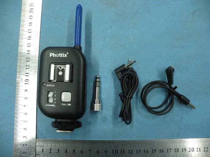
XBYFKT05ZE
Jan 11, 2011Phottix Atlas Professional Wireless Flash Trigger
Equipment Class
DSC - Part 15 Security/Remote Control Transmitter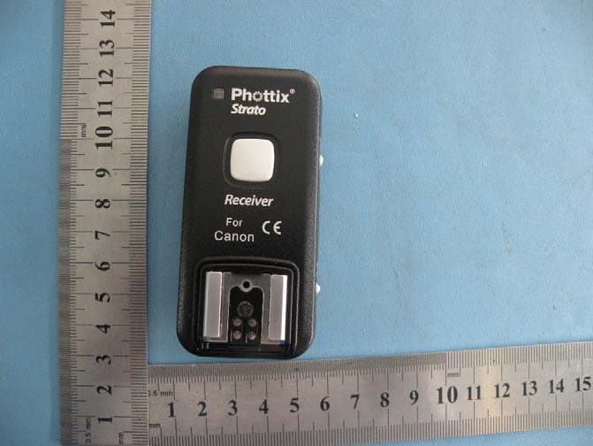
XBYSTRATO
Nov 08, 2010Phottix Strato 2.4GHz Wire/Wireless 4 in 1 Trigger
Equipment Class
DXX - Part 15 Low Power Communication Device Transmitter
XBYASTERTX
Jan 27, 2010WIRELESS FLASH TRIGGER
Equipment Class
DSC - Part 15 Security/Remote Control Transmitter
XBYASTERRX
Jan 27, 2010WIRELESS FLASH TRIGGER
Equipment Class
CYY - Communications Receiver used w/Pt 15 Transmitter