XBYSTRATOPhottix Strato 2.4GHz Wire/Wireless 4 in 1 Trigger
Shenzhen Fudasi Technology Co., Ltd.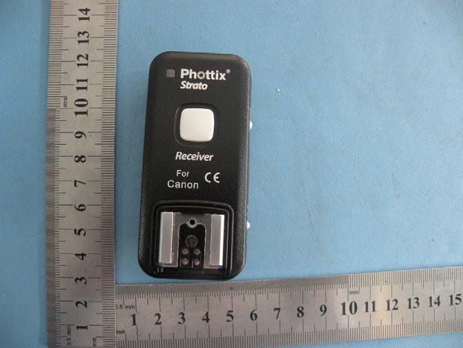
Click to zoom
Application Details
- Equipment Class
- DXX - Part 15 Low Power Communication Device Transmitter
- Date of Grant
- Nov 08, 2010
- Application Purpose
- Original Equipment
- Date of Application
- Nov 08, 2010
- Equipment Note
- Phottix Strato 2.4GHz Wire/Wireless 4 in 1 Trigger
- Frequency Range
- 2464.00000000 - 2464.00000000
- Country
- China
Documents & Files
Document Text
Text extracted from the exhibit documents filed with the FCC. Open a document above to read the original.
Users Manual
Phottix Strato transmitter Instructions Short Description *Consult your camera manual for specific settings for remote use. this product uses efficient GFSK modulation, its frequency is 2.4 G, it fits free channels in many countries.it adopts integration chip control.it has low power and super strong anti-jamming capability;it can ensure the speed,distance and stability effectively.when used with the Canon and Nikon professional flashes,it has TTL functions,and the range can be up to 100m.the Phottix Strato transmitter can be used as a wired remote.the function of the test/shutter button is the same to the cameras' shutter button:A half-press of the test/shutter button will autofocus, a full press will take a photo. 2.Main parameter Frequency: 2.464 GHz Distance: 100m + Channel: 4 channels Batteries: 2 x AAA batteries Max sync speed: 1/250 s input voltage: 2.5-3.2V Top ports:TTL port on the top of transmitter dimension:85*40*38 (LWH) Antenna: built-in PCB antenna Operating temperature: -15—65 °C Storage temperature: -30—85 °C 3.parts 1)Status LED 2)Test / Shutter Button 3)TTL Hot Shoe Port 4)Channel Selector Switch 5)Fire All Channels Switch 6)Locking Ring 7)PC input port 8)Camera Hot Shoe Connection 4.usage: Please note:Strato only can be used with compatible Canon and Nikon flashes. Status LED The Status LED on the front of the Phottix Strato transmitter will turn solid green when autofocusing (on camera or as a wireless remote) and turn red when sending a signal. Setting Channels Fire All Channels Switch To fire all flashes or strobes on different channels move the Fire All Channels Switch on the transmitter to the ON position. All nearby Strato receivers will fire flashes / strobes, or trigger connected camera shutters. Inserting Batteries Press the battery cover in while pushing it away from the Strato transmitter or receiver. The battery cover will snap open. Remove the battery cover from the Strato. Insert AAA batteries. Replace the battery cover and push back into the locked position. Test / Shutter Button The Test / Shutter Button will test fire remote flashes/strobes or take a photo when the Phottix Strato is used as a wireless shutter release. the function of the test/shutter button is the same to the cameras' shutter button-it will take a photo,A half-press of the test/shutter button will autofocus, a full press will take a photo. To Test: Press the transmitter or receiver Test / Shutter Button – flashes connected to Phottix Strato receivers on the same channel will fire. TTL function on the top of the transmitter: Turn off the camera. Slide the Strato transmitter to the camera's hot shoe mount.keep rotating the strato's lock ring until it is locked in. turn on the camera and set to TTL mode.and slide the compatible flashes to the TTL port on the top of transmitter.when take photos,the top flash can have TTL function. The usage of PC sync cable: The Strato Transmitter can also be attached to a camera’s PC Sync port if you do not wish to use the hot shoe.Connect a 3.5mm PC sync cable(included)to the camera's PC Sync Port,Connect the opposite end of the cable to the PC sync port on the transmitter.then it will has the PC sybc function. 5.Warnings - This product is a precise electronic instrument. Do not expose to damp environments or dust. - Do not drop or crush. - Do not use harsh chemical(s) or solvents to clean the body. Use a soft cloth or lens paper. - Interference: The Phottix Strato transmits and receives radio signals at 2.4 GHz. Its performance can be affected by electrical current, magnetic fields, radio signals, wireless routers, cellular phones, and other electronic devices. Environmental objects, such as large buildings or walls, trees, fences, or cars can also affect performance. If your Strato receiver will not trigger move its location slightly. changes or modifications not expressly approved by the party responsible for compliance could void the user's authority to operate the equipment. NOTE: This equipment has been tested and found to comply with the limits for a Class B digital device, pursuant to Part 15 of the FCC Rules. These limits are designed to provide reasonable protection against harmful interference in a residential installation. This equipment generates, uses and can radiate radio frequency energy and, if not installed and used in accordance with the instructions, may cause harmful interference to radio communications. However, there is no guarantee that interference will not occur in a particular installation. If this equipment does cause harmful interference to radio or television reception, which can be determined by turning the equipment off and on, the user is encouraged to try to correct the interference by one or more of the following measures: -- Reorient or relocate the receiving antenna. -- Increase the separation between the equipment and receiver. -- Connect the equipment into an outlet on a circuit different from that to which the receiver is connected. -- Consult the dealer or an experienced radio/TV technician for help. FCC ID: XBYSTRATO This device complies with Part 15 of the FCC Rules. Operation is subject to the following two conditions: (1) this device may not cause harmful interference, and (2) this device must accept any interference received, including interference that may cause undesired operation.
Cover Letter(s)
Shenzhen Fudasi Technology Co., Ltd. ______________________________________________________ SCS-F18: Project and Product Certification Representative Authorization Letter Page 1 of 2 Rev 2.0 2206 Ringwood Avenue San Jose, CA 95131 Tel: 408-526-1188 Fax: 408-526-1088 Email: [email protected] Project and Product Certification Representative Authorization Letter Revision History Reason for Amendment (current / obsolete) From To Approved Date Initial Release (current) 1.0 1.0 Nov-14-2006 Revised wording (current) 1.0 2.0 Sept–25-2007 Shenzhen Fudasi Technology Co., Ltd. ______________________________________________________ SCS-F18: Project and Product Certification Representative Authorization Letter Page 2 of 2 Rev 2.0 (October 30, 2010) To: SIEMIC, INC. 2206 Ringwood Avenue, San Jose, CA 95131 USA Dear Sir/Madam, Re: Project and Product Certification Representative Authorization Letter We, Shenzhen Fudasi Technology Co., Ltd. hereby authorize SIEMIC, INC. to act as a Certification Body for certifying for the following project(s): (Product description, model name) FCC ID: XBYSTRATO Product name: Phottix Strato 2.4GHz Wire/Wireless 4 in 1 Trigger Model: FKT05ZB(Strato) We affirm that between SIEMIC and Shenzhen Fudasi Technology Co., Ltd. , any difference in understanding, including test plan, measurement methods, applicable standards and relevant procedures and processes have been resolved prior to commencement of testing activities. Sincerely, Signature Mark Dai / Manager Title: Manager Telephone: +86-755-61116103 Email: [email protected] Date: October 30, 2010
External Photos
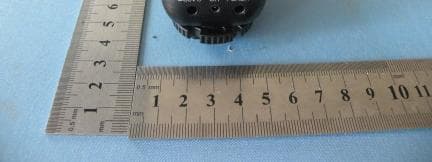
Full View Transmitter To p Vi e w Bottom View Front View Left View Rear View Right View Receive To p Vi e w Bottom View Front View Left View Rear View Right View
ID Label/Location Info
FCC ID: XBYSTRATO
ID Label/Location Info
Label Location
Internal Photos
Transmitter Top View Top View Bottom View Receive Top View ANTENNA Top View Bottom View ANTENNA
Operational Description
Description of the transmitter’s circuit: Strato is a multifunctional wireless remote control device, Strato transmitter is the transmitting unit of this product , it uses low power integrated chip controller, efficient GFSK modulation, it has strong anti-jamming capability, its frequency is 2.4 G, it fits free channels in many countries. Main features: 1.The production and emission of the radio control signal control adopts integration chip coding, 2.This part has radio-frequency power amplifier,can improve the wireless remote distance and stability effectively. 3 .RF signals can be transferred by the PCB antenna after getting through the RF power amplifier and filter. 4.When the transmitter in idle mode, it reduces average consumption current while working in guarantee quick start, there will be low power consumption, as well as improving the speed of communication.
Schematics
A B C DD C B A C16 R6 +3V C9 C10 R7 C1 CE 1 CSN 2 SCK 3 MOSI 4 MISO 5 IRQ 6 VDD 7 GND 8 XC2 9 XC1 10 VDD-PA 11 ANT1 12 ANT2 13 GND 14 VDD 15 IRED 16 GND 17 VDD 18 DVDD 19 GND 20 G U1 C7 C4 L1 C11 1 2 4 3 SW3 C12 R4 C8 R3 C3 CE CSN SCK MOSI MISO R2 R1 SHUT FOCUS R12 R11 Q2A5 A4A3 FOCUS +3V +3V C13 C18 L2 L3 +3V L4 L5 C6C2C5 PGC PGD +3V SHUT SHUT 拍照 对焦 SW4 SW3 SW2 SW1 SW4 SW3 SW2 SW1 VPP R8 IRQ C14 Q1 R5 C17 C19 C15 ANT 1 2 3 4 5 J3 1 1 2 2 3 3 J4 X1 1 J1 1 J2 D2 D1 D3 VPP vpp 1 RA0 2 RA1 3 RA2 4 RA3 5 RA4 6 RA5 7 VSS 8 RA7 9 RA6 10 RC0 11 RC1 12 RC2 13 RC3 14 RC4 15 RC5 16 RC6 17 RC7 18 VSS 19 VDD 20 RB0 21 RB1 22 RB2 23 RB3 24 RB4 25 RB5 26 RB6 27 RB7 28 U2 CE CSN SCK MOSI MISO IRQ PGC PGD LED_R LED_G FOCUS_IN SHUT_IN ALL_IN TEST LED_R LED_G +3V TEST 2 SW2 LED1 1 2 34 5 67 J5 A2 A4 1 7 25 3 6 J6 A3 SHUT A5 A2 A1 A5 N3 R10 R9 A2 N3 R13 R14 +3V C20 R15 D4 C21 T1 T2 T7 T8 T5 T6 T9 T18 T19 T20 T21 T22 T23 T24 T11 T12 T13 T14 T15 T16 T17 SW4 SW3 SW2 SW1 A4 A3 SHUT A5 A2 N3 FOCUS T25 T26 T27 T28 T29 PGC PGD VPP +3V 1 1 2 2 3 3 4 4 5 5 J8 1 1 2 2 3 3 4 4 5 5 6 6 J7 A2 N3 SHUT A5 6 5 4 3 2 1 SW1 Denomination Sheet of: 1/1 revision July 2,2010 Yuan Gui Li Auditing Date Yuan Bo Chen Shenzhen Fudasi science and Technology co.,Ltd Strato ( TX )
Test Report
Shenzhen Certification Technologh Service Co., Ltd 3F, Bldg27,Area A, Tanglang Industrial Zone, Xili Town, Nanshan District, ShenZhen, Guang dong, P.R. China. FCCID: XBYSTRATO Page 1 of 29 FITEST REPORT FCC ID: XBYSTRATO Applicant : Shenzhen Fudasi Technology Co., Ltd. Address : B Building, Shengde Industrial Park, Dalang, Longhua Town, Baoan District, Shenzhen City, China Equipment under Test (EUT): Name : Phottix Strato 2.4GHz Wire/Wireless 4 in 1 Trigger Model : FKT05ZB (Strato) Standards : FCC PART 15, SUBPART C : 2008 (Section 15.249) Report No. : STE101026826 Date of Test : October 27-28, 2010 Date of Issue : October 29, 2010 Test Result : PASS * * In the configuration tested, the EUT complied with the standards specified above Authorized Signature (Mark Zhu) General Manager The manufacture should ensure that all the products in series production are in conformity with the product sample detailed in this report. If the product in this report is used in any configuration other than that detailed in the report, the manufacturer must ensure the new system complies with all relevant standards. Any mention of Shenzhen Certification Technology Service Co., Ltd. Or test done by Shenzhen Certification Technology Service Co., Ltd. Approvals in connection with, distribution or use of the product described in this report must be approved by Shenzhen Certification Technology Service Co., Ltd. Approvals in writing. Report No.:STE101026826 FCCID: XBYSTRATO Page 2 of 29 TABLE OF CONTENT Description Page 1 General Information------------------------------------------------------------------------------------- 3 1.1 Description of Device (EUT)------------------------------------------------------------------ 3 1.2 Description of Test Facility-------------------------------------------------------------------- 4 2 EMC Equipment List --------------------------------------------------------------------------------- 4 3 Test Procedure ----------------------------------------------------------------------------------------- 5 4 Summary of Measurement ------------------------------------------------------------------------- 6 5 POWER LINE CONDUCTED EMISSION -------------------------------------------------------- 7 5.1 Conducted Emission Limits(15.209&249)-------------------------------------------------7 5.2 Test Setup-----------------------------------------------------------------------------------------7 5.3 Test Procedure-----------------------------------------------------------------------------------8 5.4 Test Resluts---------------------------------------------------------------------------------------8 6 Radiation Emission----------------------------------------------------------------------------------- 9 6.1 Radiation Emission Limits(15.209&249 (a))-----------------------------------------------9 6.2 Test Setup--------------------------------------------------------------------------------------- 10 6.3 Test Procedure--------------------------------------------------------------------------------- 11 6.4 Test Equipment Setting For emission test.est Result--------------------------------- 12 6.5 Test Condition---------------------------------------------------------------------------------- 12 6.6 Test Result-------------------------------------------------------------------------------------- 12 7 Occupied bandwidth -------------------------------------------------------------------------------- 15 7.1 Test limit------------------------------------------------------------------------------------------ 15 7.2 Method of measurement--------------------------------------------------------------------- 15 7.3 Test Setup--------------------------------------------------------------------------------------- 15 7.4 Test Results------------------------------------------------------------------------------------- 15 8 Band Edge Check------------------------------------------------------------------------------------ 17 8.1 Test limit------------------------------------------------------------------------------------------ 17 8.2 Test Procedure--------------------------------------------------------------------------------- 17 8.3 Test Setup--------------------------------------------------------------------------------------- 17 8.4 Test Result-------------------------------------------------------------------------------------- 17 9 Antenna Requirement ------------------------------------------------------------------------------ 18 9.1 Standard Requirement----------------------------------------------------------------------- 18 9.2 Antenna Connected Construction---------------------------------------------------------- 18 9.3 Result--------------------------------------------------------------------------------------------- 18 10 Photographs of Test Setup ----------------------------------------------------------------------- 19 11 Photographs of EUT--------------------------------------------------------------------------------- 20 Report No.:STE101026826 FCCID: XBYSTRATO Page 3 of 29 1 General Information 1.1 Description of Device (EUT) Trade Name : Phottix EUT : Phottix Strato 2.4GHz Wire/Wireless 4 in 1 Trigger Model No. : FKT05ZB (Strato) Type of Antenna : Integral Antenna Operation Frequency : 2464MHz Channel number : 1 (4 channels of the same frequency, just not the same encoding) Modulation type : GFSK Power Supply : DC 3V Supply by battery For Transmitter DC 3V Supply by battery or DC 5V For Receive Rated PF output Power : 92.69 dBuV (PK detector) Applicant : Shenzhen Fudasi Technology Co., Ltd. Address : B Building, Shengde Industrial Park, Dalang, Longhua Town, Baoan District, Shenzhen City, China Manufacturer : Shenzhen Fudasi Technology Co., Ltd. Address : B Building, Shengde Industrial Park, Dalang, Longhua Town, Baoan District, Shenzhen City, China Report No.:STE101026826 FCCID: XBYSTRATO Page 4 of 29 1.2 Description of Test Facility Shenzhen Certification Technology Service Co.,Ltd. …
Text truncated - open the document above for the full version.
Test Setup Photos
Radiated Emission Test Setup
Contact Information
Applicant
Yuanbo Chen(General Manager)
Test Firm
Shenzhen Certification Technology Service Co.,LtdMark Zhu
Technical Specifications
| # | Rule Parts | Frequency Range | Power Output |
|---|---|---|---|
| 1 | 15C | 2.46 GHz - 2.46 GHz | - |
Other Applications from Shenzhen Fudasi Technology Co., Ltd.
XBYFKT05ZI
May 31, 2011Phottix Strato II Multi 5-in-1 Trigger
Equipment Class
DXX - Part 15 Low Power Communication Device Transmitter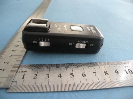
XBYFKT05ZA
May 31, 2011Phottix Odin TTL Trigger for Canon
Equipment Class
DXX - Part 15 Low Power Communication Device Transmitter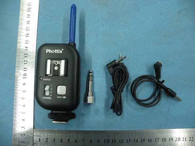
XBYFKT05ZE
Jan 11, 2011Phottix Atlas Professional Wireless Flash Trigger
Equipment Class
DSC - Part 15 Security/Remote Control Transmitter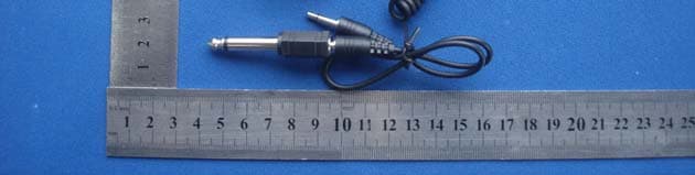
XBYASTERTX
Jan 27, 2010WIRELESS FLASH TRIGGER
Equipment Class
DSC - Part 15 Security/Remote Control Transmitter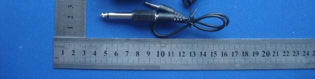
XBYASTERRX
Jan 27, 2010WIRELESS FLASH TRIGGER
Equipment Class
CYY - Communications Receiver used w/Pt 15 Transmitter