XBYFKT05ZEPhottix Atlas Professional Wireless Flash Trigger
Shenzhen Fudasi Technology Co., Ltd.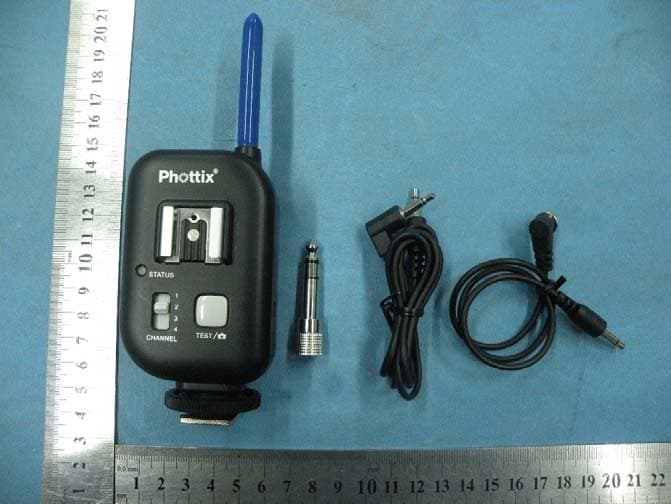
Click to zoom
Application Details
- Equipment Class
- DSC - Part 15 Security/Remote Control Transmitter
- Date of Grant
- Jan 11, 2011
- Application Purpose
- Original Equipment
- Date of Application
- Jan 11, 2011
- Equipment Note
- Phottix Atlas Professional Wireless Flash Trigger
- Frequency Range
- 344.04000000 - 344.04000000
- Country
- China
Documents & Files
Document Text
Text extracted from the exhibit documents filed with the FCC. Open a document above to read the original.
Users Manual
Phottix Atlas Instructions Parts 1) Power Switch 2) WRS Mode Switch 3) DC Power Port 4) Channel Selector Switch 5) Test / Shutter Button 6) Flash Hot Shoe Connection 7) Camera Hot Shoe Connection 8) Locking Ring 9) Flash in/out Port 10) Flash out Port 11) Antennae 12) Tripod Lug 13) Battery Cover 14) Battery Compartment Please Note: The Phottix Atlas’ hot shoe connection is designed to fire speedlight-type flashes that are triggered by the center contact. Some flashes (by Nissin, Sigma, and other manufacturers) are not triggered by the center hot shoe contact but by specific secondary contacts. Please check your flash manual for specifics. These flashes can be fired by PC Sync if available. The Atlas is designed to work in Manual Exposure mode and no TTL functions. Tip: Turn off all devices – flashes/strobes, cameras, and Phottix Atlas transceivers- when connecting and disconnecting devices. Inserting Batteries 1. Press the battery cover in while pushing it away from the Atlas. The battery cover will snap open. 2. Lift the battery cover. 3. Insert AA batteries as shown. 4. Close the battery cover and push the cover back into the locked position. Test / Shutter Button 1. The Test / Shutter Button will test fire remote flashes/strobes or take a photo when the Phottix Atlas is used as a wireless remote. 2. To Test: Press the Test / Shutter Button – remote flashes connected to Phottix Atlas transceivers on the same channel will fire. For Wireless Remote: See Using the Atlas as a wireless remote below Status LED The Status LED on the front of the Phottix Atlas will flash green when it is ready to transmit or receive signals. The LED will turn solid red when a signal is sent or received. Turning units on/off 1. To turn on the Phottix Atlas – move the power switch to the “ON” position. 2. To turn off the Phottix Atlas - move the power switch to the “OFF” position. Setting Channels 1. The Phottix Atlas has four channel settings. 2. Move the Channel Selector Switch to 1, 2, 3, or 4 to select a channel. 3. Make sure all Phottix Atlas transceivers, both on the camera and attached to flashes/strobes, are on the same channel. 4. Atlas transceivers set to channels different from the channel set on the Atlas attached to the camera will not fire. Connecting to the camera hot shoe 1. Turn off the camera and Phottix Atlas transceiver. 2. Slide the Atlas transceiver into the camera’s hot shoe mount. 3. Turn the Atlas locking ring until tight. 4. Turn on the Phottix Atlas and the camera. 5. Set the camera and flash to Manual mode. Connecting a flash to the Atlas hot shoe 1. Turn off the flash and the Phottix Atlas transceiver. 2. Slide the flash into the transceiver’s hot shoe mount. 3. Lock the flash with the flash’s locking mechanism. 4. Turn on the flash and the Phottix Atlas. 5. Set the camera and flash to Manual mode. * It is not unusual for the flash to discharge once after turning on the Phottix Atlas. Connecting a flash or studio light by PC sync 1. Turn off the flash/strobe and the Phottix Atlas transceiver. 2. Connect a compatible cable to the Phottix Atlas Flash in/out port or Flash out port. 3. Connect the opposite end of the cable to the flash or studio strobe (A 6.3 mm adaptor is included for studio strobes with larger ports). 4. Turn on the flash/strobe and the Phottix Atlas. Set the camera and flash to Manual mode. * It is not unusual for the flash to discharge once after turning on the Phottix Atlas. Connecting a local flash on a bracket (The Atlas will trigger a local flash on a bracket and a remote manual flash/strobe equipped with a Phottix Atlas) 1. Turn off the camera, flash/strobe and the Phottix Atlas transceiver. 2. Mount a Phottix Atlas in the camera’s hot shoe port. 3. Connect a compatible cable to the Phottix Atlas Flash in/out port or Flash out port. 4. Connect the opposite end of the cable to the flash’s PC Sync port. 5. Turn on the flash and Phottix Atlas. 6. Set the camera and flash to Manual mode. * It is not unusual for the flash to discharge once after turning on the Phottix Atlas. Connecting two flashes / studio lights One Phottix Atlas can be used to trigger two studio strobes or two flashes. Both flashes or studio strobes must be of the same brand, model, and voltage. DO NOT USE DIFFERENT FLASHES! Flashes have different trigger voltages – use the same make and model. Phottix is not responsible for damage resulting from improper use. 1. Turn off the camera, flash, and the Phottix Atlas transceiver. 2. Connect compatible cables to the Atlas Flash in/out port and Flash out port. 3. Connect the cables to two flashes or strobes. 4. Turn on the flashes/strobes, camera, and Phottix Atlas. 5. Set the camera and flash (if used) to Manual mode. * It is not unusual for the flash to discharge once after turning on the Phottix Atlas. Connecting to the camera PC Sync Port* (A flash on the camera hot shoe, the Atlas connected to the camera PC Sync port) 1. Turn off the camera, flash, and the Phottix Atlas transceiver. 2. Connect a compatible cable to the Phottix Atlas Flash in/out port. 3. Connect the opposite end of the cable to the camera’s PC Sync port. 4. Releasing the camera shutter will fire the hot shoe mounted flash, simultaneously transmitting a signal from the camera to the PC Sync attached Phottix Atlas. The Atlas will trigger any remote flashes or strobes connected to Phottix Atlas transceivers on the same channel. *on compatible cameras Using the Atlas as a wireless remote* 1. Turn off the camera and the Phottix Atlas transceiver. 2. Attach the correct Phottix Atlas Shutter Release Cable for your camera make and model to the Flash In/Out Port on the transceiver. 3. Attach the other end of the cable to the camera’s remote port. 4. Turn on the camera and Phottix Atlas transceiver. 5. Consult your camera manual for specific settings for remote use. 6. Using a second Phottix Atlas transceiver will allow for remote wireless shutter release functions. The Atlas test button will…
Text truncated - open the document above for the full version.
Block Diagram
MASTER MCU RADIO FREQUENCY CHIP(344.04M) 3.5MM 1 INTERFACE 3.5MM 2 INTERFACE TEST BUTTON HOT PORT 1 LED INDICATOR 344M antenna POWER SUPPLY CIRCUIT CHANNEL SELECTION SWITCH HOT PORT 2 8MHz FREQUENCY
Cover Letter(s)
Shenzhen Fudasi Technology Co., Ltd ______________________________________________________ SCS-F18: Project and Product Certification Representative Authorization Letter Page 1 of 2 Rev 2.0 2206 Ringwood Avenue San Jose, CA 95131 Tel: 408-526-1188 Fax: 408-526-1088 Email: [email protected] Project and Product Certification Representative Authorization Letter Revision History Reason for Amendment (current / obsolete) From To Approved Date Initial Release (current) 1.0 1.0 Nov-14-2006 Revised wording (current) 1.0 2.0 Sept–25-2007 Shenzhen Fudasi Technology Co., Ltd ______________________________________________________ SCS-F18: Project and Product Certification Representative Authorization Letter Page 2 of 2 Rev 2.0 (December 29, 2010) To: SIEMIC, INC. 2206 Ringwood Avenue, San Jose, CA 95131 USA Dear Sir/Madam, Re: Project and Product Certification Representative Authorization Letter We, Shenzhen Fudasi Technology Co., Ltd hereby authorize SIEMIC, INC. to act as a Certification Body for certifying for the following project(s): (Product description, model name) FCC ID: XBYFKT05ZE Product name: Phottix Atlas Professional Wireless Flash Trigger Model: FKT05ZE We affirm that between SIEMIC and Shenzhen Fudasi Technology Co., Ltd , any difference in understanding, including test plan, measurement methods, applicable standards and relevant procedures and processes have been resolved prior to commencement of testing activities. Sincerely, Signature Mark Dai / Manager Title: Manager Telephone: +86-755-61116103 Email: [email protected] Date: December 29, 2010
External Photos
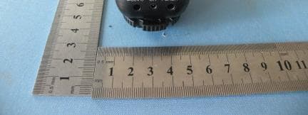
Full View To p Vi e w Bottom View Front View Left View Rear View Right View
ID Label/Location Info
FCC ID: XBYFKT05ZE
ID Label/Location Info
Label Location
Internal Photos
Top View Top View ANTENNA Top View Bottom View
Operational Description
Circuit Describe: 1.The circuit operating frequency is 344.04MHz, the frequency is fixed. MCU shared 8MHz crystal oscillator with Rf ic . 2.This product is a transceiver,when not used as a transmitter, this product would be receiving signals all the time. When given transmitting signals it can be converted to fire status automatically. 3. When at tansmit status: press the TEST button / have the hotshoe or camera flash interface a low level , MCU will transfer the processed digitally signal to RFic after receiving the high-low signals, the data would be sent by the antenna 4. When at Receiving working condition: The RF IC will transfer the signal to MCU after receiving the signal by antena,then it has controls by the MCU on output status of hot shoe socket, camera / flash interface, flash interface, status light after the processing by MCU. 5.There is no changes on the frequency (344.04M) which 4CH switch gear corresponding to,but the data signal changes.
Schematics
A B C DD C B A Title NumberRevisionSize A3 Date:10-Jan-2011Sheet of File:E:\无线闪光灯触发器\项目一\ADF70 20\11.29参数\FKT05ZC_ADF70 20_A4.DDBDrawn By: C1 105P B 1 E 3 C 2 Q2 FZT857 J4-1 J4-2 S1 SW SPST J3-1 12 3 U1 XC9111-3.3V C3 16v 47u C2 16v 47u D5 IN5819 L1 100uH hot + 1 2 3 J3 CON3 1 2 3 J5 CON3 3V3 3V3 1 2 3 4 5 J6 CON5 3V3 VPP VPP 1 2 3 4 J9 CON4 1 2 4 3 S3 SW DIP-2 SHUT_IN S2 ALL 3V3 1 J1 bat+ 1 J2 bat- 1 J7 CON1 1 J8 CON1 FOCUS_IN J3-1 FOCUS_OUTSHUT_OUT 1 J4 CON1 1 J10 CON1 J4-2 J4-1 C4 104p 3V3 VPP vpp 1 RA0 2 RA1 3 RA2 4 RA3 5 RA4 6 RA5 7 VSS 8 RA7 9 RA6 10 RC0 11 RC1 12 RC2 13 RC3 14 RC4 15 RC5 16 RC6 17 RC7 18 VSS 19 VDD 20 RB0 21 RB1 22 RB2 23 RB3 24 RB4 25 RB5 26 RB6 27 RB7 28 U4 PIC16F882-SS 3V3 FLASH_OUT 1 1 2 2 3 3 4 4 + - D1 HD06 PGC PGD PGC PGD LED1 OBJ R G R261k R271k R1 10K R7 10K R9 10K R10 10K R11 10K R5 10K TG_IN R1310K hot + LED_R LED_G R4 0R R3330R R21K FLASH_IN R1610K ALL_IN R15 1K R14 10K R12 10K FOCUS_OUT SHUT_OUT FLASH_OUT LED_R LED_G SW_L SW_H FOCUS_IN SHUT_IN TG_IN FLASH_IN ALL_IN GND Q1 KAT1298 C16 105P D2 IN5819 D3 IN5819 Vi I G G Vo O U3 XC6206-2.7V C19 106P C18 106P 1 2 3 J11 CON3 3V3 R19 10K R22 NC LED_G Vi I G G Vo O U3'NC - 6202-2.7V C20 104p R31 10K R32 10K R25 10K BAT_AD BAT_AD D4 RS1J FOR TEST C23104 R34 47K C11 20P VCC SCLK SDATA CE SLE VCC C6 105P C7 105P C8 105P C9 105P C5 105P 1 2 C13 100uF Vi I G G Vo O U2XC6206-3V 3V3 C27 24P C26 24P XT1 8M VCOIN 1 CREG1 2 VDD1 3 RFOUT 4 RFGND 5 RFIN 6 RFINB 7 RLNA 8 VDD4 9 RSET 10 CREG4 11 GND4 12 MIX_I 13 MIX_Io 14 MIX_Q 15 MIX_Qo 16 FILT_I 17 FILT_Io 18 GND3 19 FILT_Q 20 FILT_Qo 21 GND4 22 TEST_A 23 CE 24 SLE 25 SDATA 26 SREAD 27 SCLK 28 GND2 29 ADCIN 30 CREG2 31 VDD2 32 INT/LOCK 33 DATA I/O 34 DATA CLK 35 CLKOUT 36 MUXOUT 37 OSC2 38 OSC1 39 VDD3 40 CREG3 41 CPOUT 42 VDD 43 L2 44 L1 46 GND 45 GND1 47 CVCO 48 GND 0 U5 SWITCH C29 270P C21 10P L7 56NH C15 105P C43 8P2 L3 1uH Antenna (50 Ohm) ANT L6 56nH C30 333P C17 10P C25 223P L4 30nH C38 3P L5 8N2 C31 152P VCC VCC VCCVCC VCC VCC R331K1 R17 910R R24 180R C36 NC C371P R353K6 C39 5P C40 105P C41 5P C34 105P C32 5P C33 105P OUT1 C22 5P C24 105P DCLK DIO LOCK SCLK SREAD SDATA SLE CE DIO R36 330R 1 2 3 45 6 7 8 RN2 330R 1 2 3 45 6 7 8 RN3 330R OSC8M OSC8M R37 2K2 FKT05ZE ADF7020-1 A4 2011.1.5 R20 2K2 Q6 C945 C46 225P R23 1.5M C48 222P R30 470K C45 105P C10 12P R381K Q5 C945 C44 105P L9 1uH VCC R21 560K C47 332P AIN+AIN- C35 NC L8 56NH C12 5P6 C42 12P D9 BAR63-02W D8 BAR63-02W ??? AD_VCO 1.30V 0.4V 0.3V0.3V 0.55V3.0V 2.2V 0.557V 0.557V 0.97V0.3V 1.65V1.65V 0.526V 0.1V 1.30V 2.458V 56 4 3 1 2 7 8 9 10 SW1 * SW_HSW_L 3V33V3 3V3 3V3 VCC VCC AIN+ AIN- C1OUT Q7 BAV99W 2010/11/16 C1OUT 1 2 C14 100uF L2 1uH L16 1uH L11 1uH L10 1uH L13 1uH L14 1uH L15 1uH C28 102P L12 1uH change 3v to 3V3 to focus and shut ch angeD8,D9 to:BAR63-02W change:C36 8.2P---NC C43 NC---8.2P C48 102P---222P R23 1.35M---1.5M 12.6 changeC32 C39 C22 C41 --5.1P to:5P 2010. 12.8 changeRN1 RN2 1K to:330R 2010.12.18 change c26 c27 to :24P 2010.12.20
Test Report
Shenzhen Certification Technologh Service Co., Ltd 3F, Bldg27,Area A, Tanglang Industrial Zone, Xili Town, Nanshan District, ShenZhen, Guang dong, P.R. China. FCCID: XBYFKT05ZE Page 1 of 35 TEST REPORT FCC ID: XBYFKT05ZE Applicant : Shenzhen Fudasi Technology Co., Ltd Address : B Building, Shengda Industrial Park, Dalang, Longhua Town, Baoan District, Shenzhen City, China Equipment under Test (EUT): Name : Phottix Atlas Professional Wireless Flash Trigger Model : FKT05ZE Standards : FCC PART 15, SUBPART C : 2010 (Section 15.231) Report No. : STE101223011 Date of Test : December 22-26, 2010 Date of Issue : December 28, 2010 Test Result : PASS * * In the configuration tested, the EUT complied with the standards specified above Authorized Signature (Mark Zhu) General Manager The manufacture should ensure that all the products in series production are in conformity with the product sample detailed in this report. If the product in this report is used in any configuration other than that detailed in the report, the manufacturer must ensure the new system complies with all relevant standards. Any mention of Shenzhen Certification Technology Service Co., Ltd. Or test done by Shenzhen Certification Technology Service Co., Ltd. Approvals in connection with, distribution or use of the product described in this report must be approved by Shenzhen Certification Technology Service Co., Ltd. Approvals in writing. Report No.:STE101223011 FCCID: XBYFKT05ZE Page 2 of 35 TABLE OF CONTENT Description Page 1 General Information------------------------------------------------------------------------------------- 3 1.1 Description of Device (EUT)---------------------------------------------------------------------3 1.2 Description of Test Facility -----------------------------------------------------------------------4 2 EMC Equipment List --------------------------------------------------------------------------------- 4 3 Test Procedure ------------------------------------------------------------------------------------------- 5 4 Summary of Measurement ------------------------------------------------------------------------- 6 Occupied bandwidth -------------------------------------------------------------------------------------- 6 5 Radiation Emission----------------------------------------------------------------------------------- 7 5.1 Duty cycle------------------------------------------------------------------------------------------7 5.2 Radiation Emission Limits(15.209&231)------------------------------------------------- 15 5.3 Test Setup--------------------------------------------------------------------------------------- 15 5.4 Test Procedure--------------------------------------------------------------------------------- 17 5.5 Test Equipment Setting For emission test.est Result--------------------------------- 18 5.6 Test Condition---------------------------------------------------------------------------------- 18 5.7 Test Result-------------------------------------------------------------------------------------- 18 6 Occupied bandwidth -------------------------------------------------------------------------------- 22 6.1 Test limit------------------------------------------------------------------------------------------ 22 6.2 Method of measurement--------------------------------------------------------------------- 22 6.3 Test Setup--------------------------------------------------------------------------------------- 22 6.4 Test Results------------------------------------------------------------------------------------- 22 7 Transmission time ----------------------------------------------------------------------------------- 24 7.1 Test limit------------------------------------------------------------------------------------------ 24 7.2 Method of measurement--------------------------------------------------------------------- 24 7.3 Test Setup--------------------------------------------------------------------------------------- 24 7.4 Test Results------------------------------------------------------------------------------------- 24 8 Band Edge Check------------------------------------------------------------------------------------ 26 8.1 Test limit------------------------------------------------------------------------------------------ 26 Please refer section15.231 and section 15.205.----------------------------------------------- 26 8.2 Test Procedure--------------------------------------------------------------------------------- 26 8.3 Test Setup--------------------------------------------------------------------------------------- 26 8.4 Test Result-------------------------------------------------------------------------------------- 26 9 Antenna Requirement ------------------------------------------------------------------------------ 27 9.1 Standard Requirement----------------------------------------------------------------------- 27 9.2 Antenna Connected Construction---------------------------------------------------------- 27 9.3 Result--------------------------------------------------------------------------------------------- 27 10 Photographs of Test Setup ----------------------------------------------------------------------- 28 11 Photographs of EUT--------------------------------------------------------------------------------- 30 Report No.:STE101223011 FCCID: XBYFKT05ZE Page 3 of 35 1 General Information 1.1 Description of Device (EUT) Trade Name : Phottix EUT : Phottix Atlas Professional Wireless Flash Trigger Model No. : KFT05ZE Type of Antenna : Integral Antenna Operation Frequency : 344.04 MHZ Channel number : 1 (4 channels of the same frequency, just not the same encoding) Modulation type : ASK Power Supply : DC 3V Supply by battery Rated PF output Power 77.51 dBuV (PK detector) Applicant : Shenzhen Fudasi Technology Co., Ltd Address : B Building, Shengda Industrial Park, Dalang, Longhua Town, Baoan District, Shenzhen City, China Manufacturer : Shenzhen Fudasi…
Text truncated - open the document above for the full version.
Test Setup Photos
Below 1G test setup photo Above 1G test setup photo
Contact Information
Applicant
Yuanbo Chen(General Manager)
Test Firm
Shenzhen Certification Technology Service Co.,LtdMark Zhu
Technical Specifications
| # | Rule Parts | Frequency Range | Power Output |
|---|---|---|---|
| 1 | 15.231 | 344.04 MHz - 344.04 MHz | - |
Other Applications from Shenzhen Fudasi Technology Co., Ltd.
XBYFKT05ZI
May 31, 2011Phottix Strato II Multi 5-in-1 Trigger
Equipment Class
DXX - Part 15 Low Power Communication Device Transmitter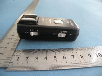
XBYFKT05ZA
May 31, 2011Phottix Odin TTL Trigger for Canon
Equipment Class
DXX - Part 15 Low Power Communication Device Transmitter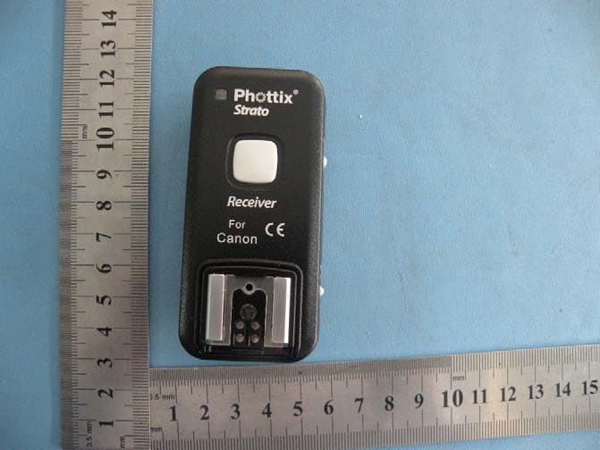
XBYSTRATO
Nov 08, 2010Phottix Strato 2.4GHz Wire/Wireless 4 in 1 Trigger
Equipment Class
DXX - Part 15 Low Power Communication Device Transmitter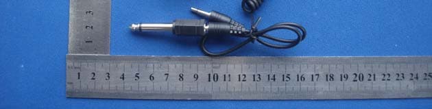
XBYASTERTX
Jan 27, 2010WIRELESS FLASH TRIGGER
Equipment Class
DSC - Part 15 Security/Remote Control Transmitter
XBYASTERRX
Jan 27, 2010WIRELESS FLASH TRIGGER
Equipment Class
CYY - Communications Receiver used w/Pt 15 Transmitter