XCNDDW262D2.0 WLCM model
Ubee Interactive Holding Corp. Taiwan Branch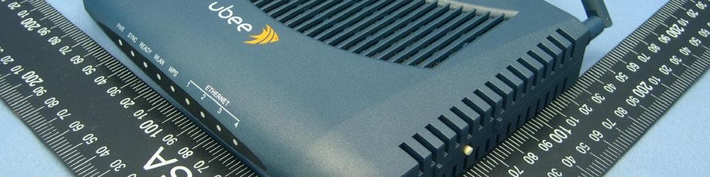
Click to zoom
Application Details
- Equipment Class
- DTS - Digital Transmission System
- Date of Grant
- Nov 29, 2011
- Application Purpose
- Original Equipment
- Date of Application
- Nov 29, 2011
- Equipment Note
- D2.0 WLCM model
- Frequency Range
- 2412.00000000 - 2462.00000000
- Country
- Taiwan
Documents & Files
Document Text
Text extracted from the exhibit documents filed with the FCC. Open a document above to read the original.
Users Manual
DDW262 D2.0 WLCM model and Router Safety and Installation Product Insert i Federal Communications Commission (FCC) Interference Statement This device has been tested and found to comply with the limits for a Class B digital device, pursuant to Part 15 of the FCC Rules. These limits are designed to provide reasonable protection against harmful interference in a residential installation. This device generates, uses, and can radiate radio frequency energy. If not installed and used in accordance with the instructions, the device may cause harmful interference to radio communications. There is no guarantee, however, that interference will not occur in a particular installation. If this device causes harmful interference to radio or television reception, which can be determined by turning it off and on, the user can try to correct the interference by one of the following measures: 噝 Increase the separation between the device and the equipment with which it is interfering (for example, a television or radio). 噝 Connect the device into an electrical outlet on a different circuit than the interfered device is connected. 噝 Consult the dealer or an experienced radio/TV technician for help. i FCC Regulatory Information This device complies with Part 15 of the FCC Rules. Operation is subject to the following two conditions: (1) This device may not cause harmful interference, and (2) this device must accept any interference received, including interference that may cause undesired operation. (3) There are two statements for this product: i FCC Radiation Exposure Statementʳ 噝This device complies with FCC radiation exposure limits set forth for an uncontrolled environment. 噝This device should be installed and operated at a minimum distance of 20cm between itself and your body. 噝This device must not be co-located or operating in conjunction with any other antenna or transmitter. i Safety Notices 1. Grounding: Install the device to include grounding the coaxial cable to the earth at the building entrance per ANSI/NFPA 70 and the National Electrical Code (NEC, in particular, Section 820.93, Grounding of the Outer Conductive Shield of a Coaxial Cable). 2. Disconnecting: If the device becomes damaged or encounters some other abnormality, disconnect the power plug from the wall outlet immediately. 3.Installing: Install the device in a location not to exceed the maximum temperature of 40 degrees Celsius (104 degrees Fahrenheit). 4.Mounting: When this device is placed upright with the aid of the stand, fix the stand at a 90-degree angle to the device. Otherwise, the 2. Connect one end of the supplied Ethernet cable to one of the ethernet ports on the device. Connect the other end to the Ethernet port on a PC. Note: Use Category 5e or Category 6 Ethernet cables with RJ45 connectors to connect Ethernet devices to the ethernet ports. This ensures Ethernet speeds (unless the computer does not support it). 3. Connect one end of the power adapter to the power port on the device. Connect the other end to an electric outlet. Important: Use only the power adapter that is shipped with the FCC Caution: Any changes or modifications not expressly approved by the party responsible for compliance could void the user's authority to operate this device. IEEE 802.11b or 802.11g or 802.11n operation of this device in the U.S.A. is firmware-limited to channels 1 through 11. device may tip over. Refer to Figure 1. Figure 1: Device Stand at 90 Degree Angle i Installation Follow these procedures to install the device. Refer to Figure 2. 1. Connect one end of a coaxial cable (not included) to the cable port on the device. Connect the other end to the cable wall outlet or a cable splitter (not included). Do not bend or over-tighten the cables as this may strain the connector and cause damage. If you plan to connect the device and a television to the same cable wall outlet, you must use a cable line splitter (not included). i Rear Panel Connections and Other Information Following are descriptions of the rear panel connections. Refer to Figure 2. 噝 power: Connect the power adapter. Only use the power adapter provided with the device. device. Press for more than 10 seconds to reset the device to the factory defaults. 噝 ethernet 1 to 4: Connect the Ethernet RJ45 cable. Connect the other to the Ethernet port on the PC or NIC. 噝 cable: Connect the coaxial cable (not included) 噝 reset: Insert a pointed object into the opening. Press for less than10 seconds to power cycle the that comes from the cable wall outlet or cable splitter (not included) to the cable connector on the back of the device. 噝WPS: Use the Wi-Fi Protected Setup found on top of the device to connect PIN-protected Wi-Fi equipment to this device. Refer to the user guide for more information. Figure 2: Rear Panel Connections i LED Descriptions and Behaviors Following are the descriptions and behaviors of the LEDs on the front of the device. Refer to Figure 3 1 2 3 device. LED COLOR DESCRIPTION POWER Green On–Device has successfully completed internal power on tests. BLINKS i fϋ power on self test failsϋ SYNCH Green Indicates the connection status between the device and the cable network. The LED is lit when the device has established a DS channel with MSO’s CMTS (Cable Modem Termination Equipment) The LED will flash during registration process network Blinks quickly–Acquiring IP address and configuration file. Off–Device receives disable configuration file message. WLAN Green On–At least one wireless client is linked to the device. Blinks–Indicates modem traffic. Off–No wireless clients connected. WPS Green On–WPS used. Off–WPS not used. ETHERNET 1,2,3,4 Green or Orange On–Connectivity between Ethernet ports on the device and computer: - Green – 100Mbps - Orange – 10Mbps Blinks–Sending or receiving data. Note: Sync and Ready LEDs blink during a firmware upgrade. Figure 3: Front Panel LEDs i Wall Mount Installation You can mount the device on a wall using the mounting brackets o…
Text truncated - open the document above for the full version.
External Photos
Report No.: 111004E05 1 CONSTRUCTION PHOTOS OF EUT Report No.: 111004E05 2 Report No.: 111004E05 3 Report No.: 111004E05 9 Report No.: 111004E05 10
ID Label/Location Info
2011.10.07 0.0 DVW2100 Yanli Yu 500.0xxxx.005 PTT Label Scale: 2/1 NOTES: 1.Material: #50 Mylar + 25# PET(matte, printable) 2.Adhesive: Acrylic 3.Adhesive thickness : 50#Mylar: 0.024+/-0.003mm 25#PET: 0.018+/-0.003mm 4.Printing Color:Black 5.Background: White 6.Packaging Style: Reel 7.The part must be RoHS compliant Package style Foxconn printing Arial,4.8pt Scale: 1/1 Vendor provide 16 45 Ubee Part No.: Input: 12V 1A Model name: DDW262 FCC ID: XCNDDW262 When label in below environment condition it must be fine (adhesived on the housing smooth face(material ABS)): Temperature: -20 ~ 80, Humidity: 5% ~ 95%R.H. 16 45 Ubee Part No.: DDW262.G Input: 12V 1A Model name: DDW262 FCC ID: XCNDDW262
ID Label/Location Info
(Fig. 1) FCC ID: XCNDDW262 FCC LABEL LOCATION The label will be permanently affixed at a conspicuous location on the device. Label
Internal Photos
Report No.: 111004E05 4 Report No.: 111004E05 5 Report No.: 111004E05 6 Report No.: 111004E05 7 Report No.: 111004E05 8 Report No.: 111004E05 9 Report No.: 111004E05 10
Operational Description
FCC ID: XCNDDW262 Report No.: RF111004E05 Operational Description This device is a Wireless Router, which operates in 2.4GHz band; the maximum data rate could be up to 65Mbps which OFDM technique. If the signal to noise radio is too poor which could not support 65Mbps, the 11Mbps data rate with DSSS technique will be applied. The transmitter of the EUT is powered by 12Vdc AC adapter. The antenna is Dipole antenna with RE-SMA antenna connector. For more detailed instruction, please take a look at the user’s manual.
RF Exposure Info
Report No.: SA111004E05 Report Format Version 4.0.0. 1 RF EXPOSURE REPORT REPORT NO.: SA111004E05 MODEL NO.: DDW262 FCC ID: XCNDDW262 RECEIVED: Oct. 04, 2011 TESTED: Oct. 27, 2011 ISSUED: Nov. 28, 2011 APPLICANT: Ubee Interactive Corp. ADDRESS: 10F-1, No.5 Taiyuan 1st St. Jhubei City Hsinchu County 302, Taiwan, R.O.C. ISSUED BY: Bureau Veritas Consumer Products Services (H.K.) Ltd., Taoyuan Branch Hsin Chu Laboratory LAB ADDRESS: No. 81-1, Lu Liao Keng, 9th Ling, Wu Lung Tsuen, Chiung Lin Hsiang, Hsin Chu Hsien 307, Taiwan This test report consists of 5 pages in total. It may be duplicated completely for legal use with the approval of the applicant. It should not be reproduced, except in full, without the written approval of our laboratory. The client should not use it to claim product certification, approval or endorsement by any government agency. The test results in the report only apply to the tested sample. Report No.: SA111004E05 Report Format Version 4.0.0. 2 TABLE OF CONTENTS RELEASE CONTROL RECORD....................................................................................3 1. CERTIFICATION.....................................................................................................4 2. RF EXPOSURE LIMIT.............................................................................................5 3. MPE CALCULATION FORMULA............................................................................5 4. CLASSIFICATION...................................................................................................5 5. CALCULATION RESULT OF MAXIMUM CONDUCTED POWER..........................5 Report No.: SA111004E05 Report Format Version 4.0.0. 3 RELEASE CONTROL RECORD ISSUE NO. REASON FOR CHANGE DATE ISSUED SA111004E05 Original release Nov. 28, 2011 Report No.: SA111004E05 Report Format Version 4.0.0. 4 1.CERTIFICATION PRODUCT: D2.0 WLCM model BRAND NAME: Ubee MODEL NO.: DDW262 TEST SAMPLE: ENGINEERING SAMPLE TESTED: Oct. 27, 2011 APPLICANT: Ubee Interactive Corp. STANDARDS: FCC Part 2 (Section 2.1091) FCC OET Bulletin 65, Supplement C (01-01) IEEE C95.1 The above equipment (Model: DDW262) has been tested by Bureau Veritas Consumer Products Services (H.K.) Ltd., Taoyuan Branch, and found compliance with the requirement of the above standards. The test record, data evaluation & Equipment Under Test (EUT) configurations represented herein are true and accurate accounts of the measurements of the sample’s EMC characteristics under the conditions specified in this report. PREPARED BY : , DATE: Sep. 23, 2011 ( Lori Chung, Specialist) APPROVED BY : , DATE: Sep. 23, 2011 ( May Chen, Deputy Manager ) Report No.: SA111004E05 Report Format Version 4.0.0. 5 2. RF EXPOSURE LIMIT LIMITS FOR MAXIMUM PERMISSIBLE EXPOSURE (MPE) FREQUENCY RANGE (MHz) ELECTRIC FIELD STRENGTH (V/m) MAGNETIC FIELD STRENGTH (A/m) POWER DENSITY (mW/cm 2 ) AVERAGE TIME (minutes) LIMITS FOR GENERAL POPULATION / UNCONTROLLED EXPOSURE 300-1500 ... ... F/1500 30 1500-100,000 ... ... 1.0 30 F = Frequency in MHz 3. MPE CALCULATION FORMULA Pd = (Pout*G) / (4*pi*r 2 ) where Pd = power density in mW/cm 2 Pout = output power to antenna in mW G = gain of antenna in linear scale pi = 3.1416 r = distance between observation point and center of the radiator in cm 4. CLASSIFICATION The antenna of this product, under normal use condition, is at least 20cm away from the body of the user. So, this device is classified as Mobile Device. 5. CALCULATION RESULT OF MAXIMUM CONDUCTED POWER For WLAN: 15.247(2.4GHz) FREQUENCY BAND (MHz) CONDUCTED POWER (mW) ANTENNA GAIN (dBi) DISTANCE (cm) POWER DENSITY (mW/ cm 2 ) LIMIT (mW/cm 2 ) 2412-2462 186.2 2 20 0.059 1.00 ---END---
Test Report
Report No.: RF111004E05 1 Report Format Version 4.0.0 FCC TEST REPORT REPORT NO.: RF111004E05 MODEL NO.: DDW262 FCC ID: XCNDDW262 RECEIVED: Oct. 04, 2011 TESTED: Oct. 11 to Nov. 15, 2011 ISSUED: Nov. 28, 2011 APPLICANT: Ubee Interactive Corp. ADDRESS: 10F-1, No.5 Taiyuan 1st St. Jhubei City Hsinchu County 302, Taiwan, R.O.C. ISSUED BY: Bureau Veritas Consumer Products Services (H.K.) Ltd., Taoyuan Branch Hsin Chu Laboratory LAB ADDRESS : No. 81-1, Lu Liao Keng, 9th Ling,Wu Lung Tsuen, Chiung Lin Hsiang, Hsin Chu Hsien 307, Taiwan TEST LOCATION (1): No. 81-1, Lu Liao Keng, 9th Ling,Wu Lung Tsuen, Chiung Lin Hsiang, Hsin Chu Hsien 307, Taiwan TEST LOCATION (2): No. 49, Ln. 206, Wende Rd., Shangshan Tsuen, Chiung Lin Hsiang, Hsin Chu Hsien 307, Taiwan This test report consists of 66 pages in total. It may be duplicated completely for legal use with the approval of the applicant. It should not be reproduced except in full, without the written approval of our laboratory. The client should not use it to claim product certification, approval, or endorsement by TAF or any government agencies. The test results in the report only apply to the tested sample. Report No.: RF111004E05 2 Report Format Version 4.0.0 Table of Contents RELEASE CONTROL RECORD........................................................................................4 1. CERTIFICATION....................................................................................................5 2. SUMMARY OF TEST RESULTS............................................................................6 2.1 MEASUREMENT UNCERTAINTY..........................................................................7 3. GENERAL INFORMATION.....................................................................................8 3.1 GENERAL DESCRIPTION OF EUT.......................................................................8 3.2 DESCRIPTION OF TEST MODES.......................................................................10 3.2.1 TEST MODE APPLICABILITY AND TESTED CHANNEL DETAIL........................11 3.3 GENERAL DESCRIPTION OF APPLIED STANDARDS.......................................13 3.4 DESCRIPTION OF SUPPORT UNITS..................................................................14 3.5 CONFIGURATION OF SYSTEM UNDER TEST...................................................15 4. TEST TYPES AND RESULTS..............................................................................16 4.1 CONDUCTED EMISSION MEASUREMENT........................................................16 4.1.1 LIMITS OF CONDUCTED EMISSION MEASUREMENT......................................16 4.1.2 TEST INSTRUMENTS..........................................................................................16 4.1.3 TEST PROCEDURES..........................................................................................17 4.1.4 DEVIATION FROM TEST STANDARD.................................................................17 4.1.5 TEST SETUP.......................................................................................................18 4.1.6 EUT OPERATING CONDITIONS.........................................................................18 4.1.7 TEST RESULTS...................................................................................................19 4.2 RADIATED EMISSION MEASUREMENT.............................................................21 4.2.1 LIMITS OF RADIATED EMISSION MEASUREMENT...........................................21 4.2.2 TEST INSTRUMENTS..........................................................................................22 4.2.3 TEST PROCEDURES..........................................................................................23 4.2.4 DEVIATION FROM TEST STANDARD.................................................................23 4.2.5 TEST SETUP.......................................................................................................24 4.2.6 EUT OPERATING CONDITIONS.........................................................................24 4.2.7 TEST RESULTS...................................................................................................25 4.3 6dB BANDWIDTH MEASUREMENT....................................................................48 4.3.1 LIMITS OF 6dB BANDWIDTH MEASUREMENT..................................................48 4.3.2 TEST INSTRUMENTS..........................................................................................48 4.3.3 TEST PROCEDURE.............................................................................................48 4.3.4 DEVIATION FROM TEST STANDARD.................................................................48 4.3.5 TEST SETUP.......................................................................................................48 4.3.6 EUT OPERATING CONDITIONS.........................................................................48 4.3.7 TEST RESULTS...................................................................................................49 4.4 MAXIMUM PEAK OUTPUT POWER....................................................................52 4.4.1 LIMITS OF MAXIMUM PEAK OUTPUT POWER MEASUREMENT.....................52 4.4.2 INSTRUMENTS....................................................................................................52 4.4.3 TEST PROCEDURES..........................................................................................52 Report No.: RF111004E05 3 Report Format Version 4.0.0 4.4.4 DEVIATION FROM TEST STANDARD.................................................................52 4.4.5 TEST SETUP.......................................................................................................52 4.4.6 EUT OPERATING CONDITIONS.........................................................................52 4.4.7 TEST RESULTS...................................................................................................53 4.5 POWER SPECTRAL DENSITY …
Text truncated - open the document above for the full version.
Test Setup Photos
1 PHOTOGRAPHS OF THE TEST CONFIGURATION CONDUCTED EMISSION TEST 2 RADIATED EMISSION TEST
Contact Information
Applicant
Lily Liu(Manager)
Technical Contact
Bureau Veritas CPS (H.K.) Ltd. Taoyuan BranchHank Chung
[email protected]886-3-593-5343
81-1, Lu Laio Keng, 9th Ling, Wu Lung Tsuen, Chiun · Hsinchu Hsien · Taiwan
Non-Technical Contact
Bureau Veritas CPS (H.K.) Ltd. Taoyuan BranchNatacha Chen
[email protected]886-3-3183232
Test Firm
Bureau Veritas CPS (H.K.) Ltd. Taoyuan BranchRichard Chen
Technical Specifications
| # | Rule Parts | Frequency Range | Power Output |
|---|---|---|---|
| 1 | 15C | 2.41 GHz - 2.46 GHz | 186.00 mW |
Other Applications from Ubee Interactive Holding Corp. Taiwan Branch
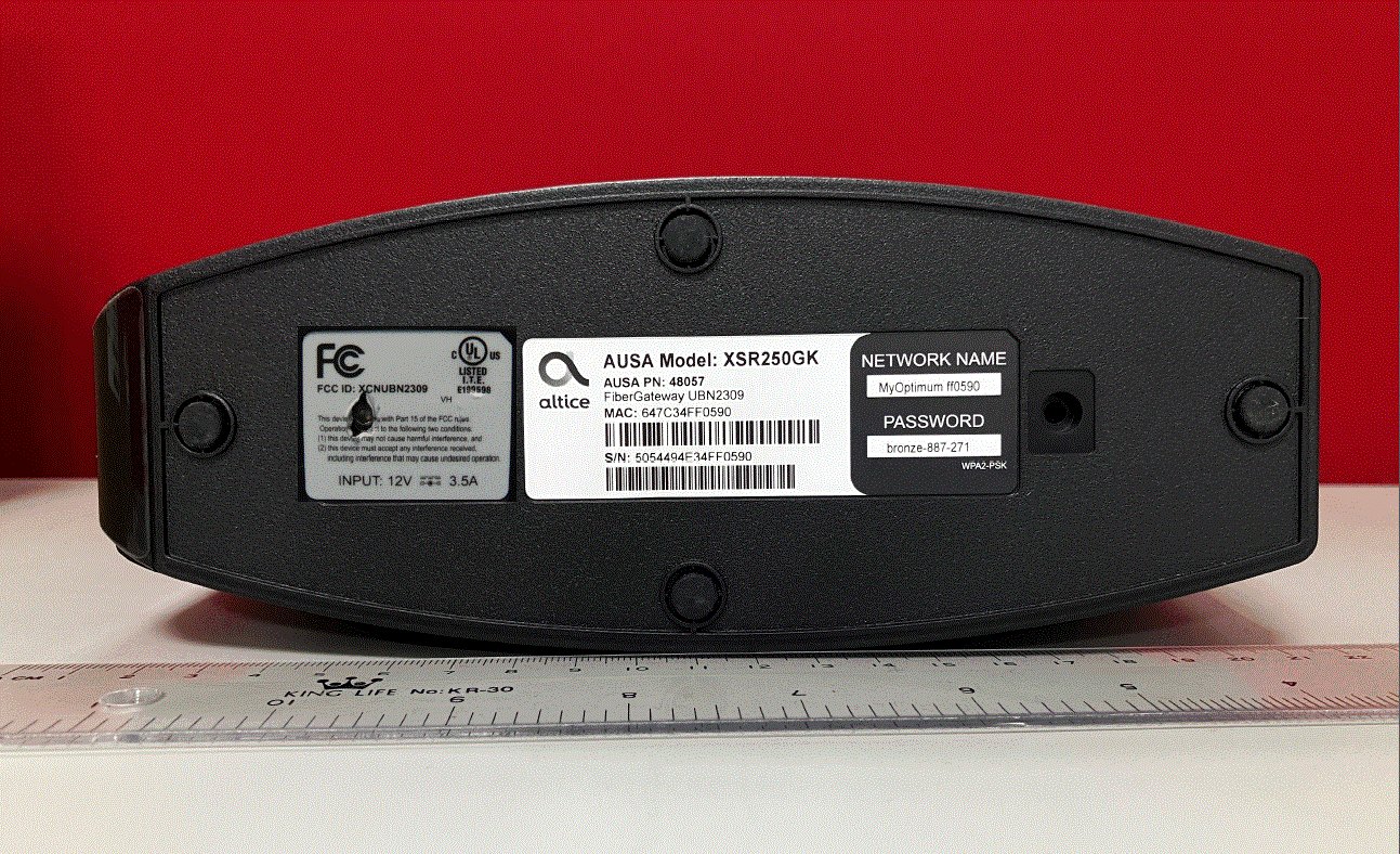
XCNUBN2309
Aug 27, 2023XGS-PON
Equipment Class
DTS - Digital Transmission System
XCNUBN2310
Jul 25, 2023GPON
Equipment Class
NII - Unlicensed National Information Infrastructure TX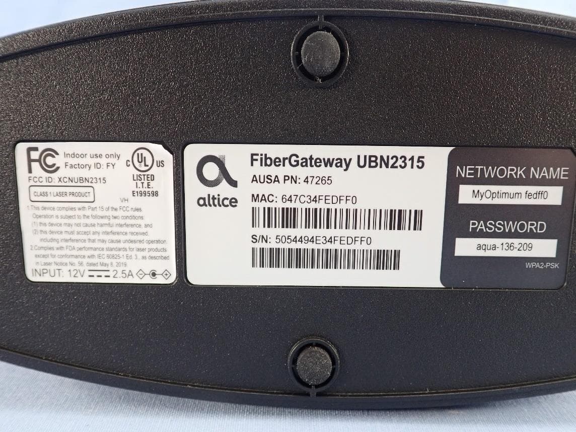
XCNUBN2315
Mar 04, 2023GPON IAD
Equipment Class
6ID - 15E 6 GHz Low Power Indoor Access Point
XCNUBC1340
Feb 01, 2023WeMTA
Equipment Class
6ID - 15E 6 GHz Low Power Indoor Access Point
XCNUBC1330
Jan 28, 2023Docsis3.1 advance WiFi 6E Voice Gateway
Equipment Class
6ID - 15E 6 GHz Low Power Indoor Access Point