XCNDVW222BCable Modem BCM3379 WeMTA
Ubee Interactive Holding Corp. Taiwan Branch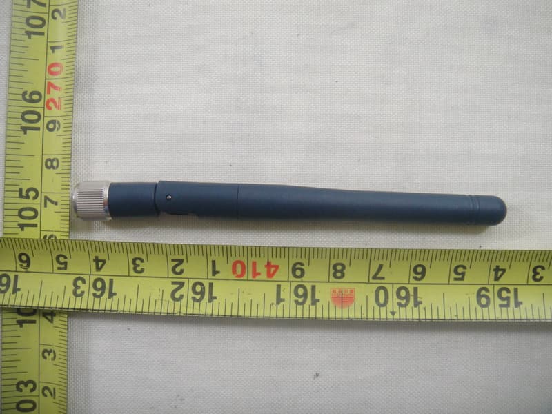
Click to zoom
Application Details
- Equipment Class
- DTS - Digital Transmission System
- Date of Grant
- Aug 15, 2011
- Application Purpose
- Original Equipment
- Date of Application
- Aug 14, 2011
- Equipment Note
- Cable Modem BCM3379 WeMTA
- Frequency Range
- 2412.00000000 - 2462.00000000
- Country
- Taiwan
Documents & Files
Document Text
Text extracted from the exhibit documents filed with the FCC. Open a document above to read the original.
Users Manual
1 DVW222B D2.0 Voice Wireless Gateway Safety and Installation Product Insert ◆ Federal Communications Commission (FCC) Interference Statement This device has been tested and found to comply with the limits for a Class B digital device, pursuant to Part 15 of the FCC Rules. These limits are designed to provide reasonable protection against harmful interference in a residential installation. This device generates, uses, and can radiate radio frequency energy. If not installed and used in accordance with the instructions, the device may cause harmful interference to radio communications. There is no guarantee, however, that interference will not occur in a particular installation. If this device causes harmful interference to radio or television reception, which can be determined by turning it off and on, the user can try to correct the interference by one of the following measures: - Increase the separation between the device and the equipment with which it is interfering (for example, a television or radio). - Connect the device into an electrical outlet on a different circuit than the interfered device is connected. - Consult the dealer or an experienced radio/TV technician for help. ◆ FCC Regulatory Information This device complies with Part 15 of the FCC Rules. Operation is subject to the following two conditions: (1) This device may not cause harmful interference, and (2) this device must accept any interference received, including interference that may cause undesired operation. FCC Caution: Any changes or modifications not expressly approved by the party responsible for compliance could void the user's authority to operate this device. IEEE 802.11b or 802.11g operation of this device in the U.S.A. is firmware-limited to channels 1 through 11. ◆ FCC Radiation Exposure Statement This device complies with FCC radiation exposure limits set forth for an uncontrolled environment. This device should be installed and operated at a minimum distance of 20cm between itself and your body. This device must not be co-located or operating in conjunction with any other antenna or transmitter. 2 ◆ Safety Notices 1. Installation of the device should include grounding the coaxial cable to the earth at the building entrance per ANSI/NFPA 70 and the National Electrical Code (NEC, in particular, Section 820.93, Grounding of the Outer Conductive Shield of a Coaxial Cable). 2. Disconnecting the Device: If the device becomes damaged or encounters some other abnormality, disconnect the power plug from the wall outlet immediately. 3. The device should be installed in a location not to exceed the maximum temperature of 40 degrees Celsius (104 degrees Fahrenheit). 4. When this device is placed upright with the aid of the stand, the stand must be fixed at a 90 degree angle to the device. Otherwise, the device has the risk of tipping over. Refer to Figure 1. Figure 1: Device Stand at 90 Degree Angle ◆ Installation Follow the procedures below and refer to Figure 2 to install the device. 1. Connect one end of a coaxial cable (not included) to the CABLE port on the device. Connect the other end to a cable splitter or the cable wall outlet. Be sure not to bend or over- tighten the cables as this may strain the connector and cause damage. If you plan to connect the device and a television to the same cable wall outlet, you must use a cable line splitter (not included). 2. Connect one end of the supplied Ethernet cable to the ETHERNET port on the device. Connect the other end to the ETHERNET port on a PC. Note: Category 5e or Category 6 Ethernet cables with RJ45 connectors must be used when connecting Ethernet devices to the LAN ports. This ensures Gigabit Ethernet speeds (unless the computer does not support it). 3. Connect one end of an RJ11 phone cable to one of the TEL ports on the device (a port that has been provisioned for voice service as specified by the service provider). Connect the other end to the phone port of the telephone. Note: If voice service is not provisioned through the service provider, telephone service is not available. 4. Connect one end of the power adapter to the POWER port on the device. Connect the other end to an electric outlet. Important: Use only the power adapter that is shipped with the device. 3 ◆ Additional Information on Rear Panel Connections and Other Information 1. POWER: Use to connect power adapter. Only use the power adapter that is provided with the device. 2. TEL1/TEL2: Use to connect the phone line RJ11 cable. The other end connects to the phone line port on the Telephone set. 3. ETHERNET: Use to connect the Ethernet RJ45 cable. The other end connects to the Ethernet port on the PC or NIC. 4. RESET button: Use to reset the device to the factory defaults. Insert a pointed object into the button opening and hold for more than 10 seconds. The device resets and reboots. Note: Not all parameters are reset to factory defaults. Refer to the User Guide for more information. 5. CABLE Connector: Use to connect the coaxial cable (not included) that comes from the cable splitter (not included) or the cable wall outlet. 6. Battery: Use this slot to contain the battery. The slot can be opened/closed to insert or replace the battery. Note: Only use the battery provided with the device. 7. WPS (located on the front of the device): Use the Wi-Fi Protected Setup (WPS) method to connect PIN-protected Wi-Fi equipment to this device. Refer to the User Manual for more information. Figure 2: Rear Panel Connections 4 ◆ LEDs on Front Panel of Device See Figure 3 and the LED descriptions to understand LED behavior. Figure 3: Front Panel LEDs LED COLOR DESCRIPTION Power Green Indicates the device has successfully completed internal power‐on tests. LED flashes if power‐on self test fails. DS Green Indicates data is being received from the cable network. Indicates the device has acquired a DS channel. US Green Indicates data is being transmitted to the device. Indicates the device has acquired an ups…
Text truncated - open the document above for the full version.
Cover Letter(s)
CERTIFICATE OF COMPLIANCE Ref No.: NEI-FCCE-1-1107C174 Date of Issue: Aug. 04, 2011 Authorized under Declaration of Conformity according to 47 CFR, Part 2 and Part 15 of the FCC Rules. The product listed in follows was (were) tested in the Neutron EMC Laboratory to comply with the criteria limits Class B of conducted and radiated emissions of the Technical Standards FCC Part 15, Subpart B, established by the FCC, USA. Equipment Cable Modem BCM3379 WeMTA Model Name DVW222B Brand Name Ubee Applicant HONG HAI PRECISION INDUSTRY CO LTD Address 5TH FL-1 SCIENCE BASED INDUSTRIAL PARK 5 HSIN-AN RD HSINCHU 300 TAIWAN Measurement ANSI C63.4 (2003) Method The test data, data evaluation, and equipment configuration contained in our test report (Ref No. NEI-FCCE-1-1107C174) were obtained utilizing the test procedures, test instruments, test sites that has been accredited by the Authority of NVLAP and TAF according to the ISO-17025 quality assessment standard and technical standard(s). The test data contained in the referenced test report relate only to the EUT sample and item(s) tested. Andy Chiu Authorized Signatory Neutron Engineering Inc. B1, No.37, Lane 365, Yang Guang St., NeiHu District 114., Taipei, Taiwan TEL:+886-2-2657-3299 FAX:+886-2-2657-3331
External Photos
Neutron Engineering Inc. Project No.: 1107C174 Page 2 of 18 1107C174 1107C174 Neutron Engineering Inc. Project No.: 1107C174 Page 2 of 18 1107C174 1107C174 Neutron Engineering Inc. Project No.: 1107C174 Page 3 of 18 1107C174 1107C174 Neutron Engineering Inc. Project No.: 1107C174 Page 3 of 18 1107C174 1107C174 Neutron Engineering Inc. Project No.: 1107C174 Page 4 of 18 1107C174 1107C174 Neutron Engineering Inc. Project No.: 1107C174 Page 4 of 18 1107C174 1107C174 Neutron Engineering Inc. Project No.: 1107C174 Page 5 of 18 1107C174 1107C174 Neutron Engineering Inc. Project No.: 1107C174 Page 5 of 18 1107C174 1107C174 Neutron Engineering Inc. Project No.: 1107C174 Page 6 of 18 1107C174 1107C174 Neutron Engineering Inc. Project No.: 1107C174 Page 6 of 18 1107C174 1107C174
ID Label/Location Info
2011.07.13 0.1 N/A2011.07.19Add FCC ID partLongli 0.2 N/A2011.07.22Delete UL and Canada cert. partsLongli 0.3 N/A2011.07.25Update Model name and FCC IDLongli 0.0 DVW2100 Yanli Yu 500.00xxx.005 PTT Label Vendor Code Scale: 2/1 NOTES: 1.Material: #50 Mylar + 25# PET(matte, printable) 2.Adhesive: Acrylic 3.Adhesive thickness : 50#Mylar: 0.024+/-0.003mm 25#PET: 0.018+/-0.003mm 4.Printing Color:Black 5.Background: White 6.Packaging Style: Reel 7.The part must be RoHS compliant Package style Foxconn printing Arial,4.8pt Scale: 1/1 Vendor provide 16 45 Ubee Part No.: Input: 12V 1A Model name: DVW222B FCC ID: XCNDVW222B 16 45 Ubee Part No.: DVW222B.F Input: 12V 1A Model name: DVW222B FCC ID: XCNDVW222B 2011.04.02 2011.07.13Add PTT LabelLongli1.0 N/A N/A DVW2100 Yanli Yu HH Label PTT Label Housing Label T T T
Internal Photos
Neutron Engineering Inc. Project No.: 1107C174 Page 7 of 18 1107C174 1107C174 Neutron Engineering Inc. Project No.: 1107C174 Page 7 of 18 1107C174 1107C174 Neutron Engineering Inc. Project No.: 1107C174 Page 8 of 18 1107C174 1107C174 Neutron Engineering Inc. Project No.: 1107C174 Page 8 of 18 1107C174 1107C174 Neutron Engineering Inc. Project No.: 1107C174 Page 9 of 18 1107C174 1107C174 Neutron Engineering Inc. Project No.: 1107C174 Page 9 of 18 1107C174 1107C174 Neutron Engineering Inc. Project No.: 1107C174 Page 10 of 18 1107C174 1107C174 Neutron Engineering Inc. Project No.: 1107C174 Page 10 of 18 1107C174 1107C174 Neutron Engineering Inc. Project No.: 1107C174 Page 11 of 18 1107C174 1107C174 Neutron Engineering Inc. Project No.: 1107C174 Page 11 of 18 1107C174 1107C174 Neutron Engineering Inc. Project No.: 1107C174 Page 12 of 18 1107C174 1107C174 Neutron Engineering Inc. Project No.: 1107C174 Page 12 of 18 1107C174 1107C174 Neutron Engineering Inc. Project No.: 1107C174 Page 13 of 18 1107C174 1107C174 Neutron Engineering Inc. Project No.: 1107C174 Page 13 of 18 1107C174 1107C174 Neutron Engineering Inc. Project No.: 1107C174 Page 14 of 18 1107C174 1107C174 Neutron Engineering Inc. Project No.: 1107C174 Page 14 of 18 1107C174 1107C174 Neutron Engineering Inc. Project No.: 1107C174 Page 15 of 18 1107C174 1107C174 Neutron Engineering Inc. Project No.: 1107C174 Page 15 of 18 1107C174 1107C174 Neutron Engineering Inc. Project No.: 1107C174 Page 16 of 18 1107C174 1107C174 Neutron Engineering Inc. Project No.: 1107C174 Page 16 of 18 1107C174 1107C174 Neutron Engineering Inc. Project No.: 1107C174 Page 17 of 18 1107C174 1107C174 Neutron Engineering Inc. Project No.: 1107C174 Page 17 of 18 1107C174 1107C174 Neutron Engineering Inc. Project No.: 1107C174 Page 18 of 18 1107C174
RF Exposure Info
Neutron Engineering Inc. FCC RF EXPOSURE REPORT FCC ID: XCNDVW222B Project No. : 1107C174 Equipment : Cable Modem BCM3379 WeMTA Model : DVW222B Applicant : Ubee Interactive Corp. Address : 6F-9, No.38, Taiyuan St. Jhubei According: : FCC Guidelines for Human Exposure IEEE C95.1 Neutron Engineering Inc. No.3, Jinshagang 1st Road, ShiXia, Dalang Town, Dong Guan, China. TEL : (0769) 8318-3000 FAX : (0769) 8319-6000 Neutron Engineering Inc. MPE CALCULATION METHOD: Calculation Method of RF Safety Distance: where: S = power density P = power input to the antenna G = power gain of the antenna in the direction of interest relative to an isotropic radiator R = distance to the center of radiation of the antenna Ant. Brand name Model Name Antenna TypeConnector Gain (dBi) 1 N/A FX01Z34-0 G-EF Dipole AntennaU.FL 2.0 TEST RESULTS EUT: Cable Modem BCM3379 WeMTA Model Name : DVW222B Temperature: 25 °C Relative Humidity: 60 % Pressure: 1012 hPa Test Voltage : AC 120V/60Hz Test Mode : TX B MODE CH01/CH06/CH11 Antenna Gain (dBi) Antenna Gain (numeric) Peak Output Power (dBm) Peak Output Power (mW) Power Density (S) (mW/cm 2 ) Limit of Power Density (S) (mW/cm 2 ) Te s t Result 2.0 1.5849 17.17 52.1195 0.016441841 Complies 2.0 1.5849 17.22 52.7230 0.016632231 Complies 2.0 1.5849 17.38 54.7016 0.017256411 Complies Neutron Engineering Inc. EUT: Cable Modem BCM3379 WeMTA Model Name : DVW222B Temperature: 25 °C Relative Humidity: 60 % Pressure: 1012 hPa Test Voltage : AC 120V/60Hz Test Mode : TX G MODE CH01/CH06/CH11 Antenna Gain (dBi) Antenna Gain (numeric) Peak Output Power (dBm) Peak Output Power (mW) Power Density (S) (mW/cm 2 ) Limit of Power Density (S) (mW/cm 2 ) Te s t Result 2.0 1.5849 15.12 32.5087 0.010255351 Complies 2.0 1.5849 14.92 31.0456 0.009793781 Complies 2.0 1.5849 15.25 33.4965 0.010566971 Complies EUT: Cable Modem BCM3379 WeMTA Model Name : DVW222B Temperature: 25 °C Relative Humidity: 60 % Pressure: 1012 hPa Test Voltage : AC 120V/60Hz Test Mode : TX N20MHz MODE CH01/CH06/CH11 Antenna Gain (dBi) Antenna Gain (numeric) Peak Output Power (dBm) Peak Output Power (mW) Power Density (S) (mW/cm 2 ) Limit of Power Density (S) (mW/cm 2 ) Te s t Result 2.0 1.5849 14.74 29.7852 0.009396161 Complies 2.0 1.5849 14.82 30.3389 0.009570851 Complies 2.0 1.5849 15.00 31.6228 0.009975861 Complies
Test Report
Neutron Engineering Inc. Report No.: NEI-FCCP-1-1107C174 Page 1 of 96 FCC Radio Test Report FCC ID: XCNDVW222B This report concerns (check one) : Original Grant Class II Change Issued Date : Aug. 04, 2011 Project No. : 1107C174 Equipment : Cable Modem BCM3379 WeMTA Model Name : DVW222B Applicant : Ubee Interactive Corp. Address : 6F-9, No.38, Taiyuan St. Jhubei Hsinchu Taiwan Tested by: Neutron Engineering Inc. EMC Laboratory Date of Receipt: Jul. 20, 2011 Date of Test: Jul. 20, 2011 ~ Aug. 03, 2011 Testing Engineer : (Ares Liu) Technical Manager : (Leo Hung) Authorized Signatory : (Steven Lu) Neutron Engineering Inc. No.3,Jinshagang 1st Road, ShiXia, Dalang Town, Dong Guan, China. TEL : (0769) 8318-3000 FAX : (0769) 8319-6000 Neutron Engineering Inc. Report No.: NEI-FCCP-1-1107C174 Page 2 of 96 Declaration Neutron represents to the client that testing is done in accordance with standard procedures as applicable and that test instruments used has been calibrated with the standards traceable to National Measurement Laboratory (NML) of R.O.C, or National Institute of Standards and Technology (NIST) of U.S.A. Neutron's reports apply only to the specific samples tested under conditions. It is manufacture’s responsibility to ensure that additional production units of this model are manufactured with the identical electrical and mechanical components. Neutron shall have no liability for any declarations, inferences o r generalizations drawn by the client or others from Neutron issued reports. Neutron’s reports must not be used by the client to claim product endorsement by the authorities or any agency of the Government. This report is the confidential property of the client. As a mutual protection to the clients, the public and Neutron-self, extracts from the test report shall not be reproduced except in full with Neutron’s authorized written approval. Neutron’s laboratory quality assurance procedures are in compliance with the ISO Guide 17025 requirements, and accredited by the conformity assessment authorities listed in this test report. Limitation For the use of the authority's logo is limited unless the Test Standard(s)/Scope(s)/Item(s) mentioned in this test report is (are) included in the conformity assessment authorities acceptance respective. Neutron Engineering Inc. Report No.: NEI-FCCP-1-1107C174 Page 3 of 96 Table of Contents Page 1 . CERTIFICATION 5 2 . SUMMARY OF TEST RESULTS 6 2.1 TEST FACILITY 7 2.2 MEASUREMENT UNCERTAINTY 7 3 . GENERAL INFORMATION 8 3.1 GENERAL DESCRIPTION OF EUT 8 3.2 DESCRIPTION OF TEST MODES 10 3.3 TABLE OF PARAMETERS OF TEXT SOFTWARE SETTING 11 3.4 BLOCK DIGRAM SHOWING THE CONFIGURATION OF SYSTEM TESTED 12 3.5 DESCRIPTION OF SUPPORT UNITS (RADIATED MODE) 13 4 . EMC EMISSION TEST 14 4.1 CONDUCTED EMISSION MEASUREMENT 14 4.1.1 POWER LINE CONDUCTED EMISSION LIMITS 14 4.1.2 MEASUREMENT INSTRUMENTS LIST AND SETTING 14 4.1.3 TEST PROCEDURE 15 4.1.4 DEVIATION FROM TEST STANDARD 15 4.1.5 TEST SETUP 15 4.1.6 EUT OPERATING CONDITIONS 15 4.1.7 TEST RESULTS 16 4.2 RADIATED EMISSION MEASUREMENT 20 4.2.1 RADIATED EMISSION LIMITS 20 4.2.2 MEASUREMENT INSTRUMENTS LIST ANS SETTING 21 4.2.3 TEST PROCEDURE 22 4.2.4 DEVIATION FROM TEST STANDARD 22 4.2.5 TEST SETUP 23 4.2.6 EUT OPERATING CONDITIONS 23 4.2.7 TEST RESULTS (BETWEEN 30 – 1000 MHZ) 24 4.2.8 TEST RESULTS (ABOVE 1000 MHZ) 26 5 . BANDWIDTH TEST 62 5.1 APPLIED PROCEDURES / LIMIT 62 5.1.1 MEASUREMENT INSTRUMENTS LIST 62 5.1.2 TEST PROCEDURE 62 5.1.3 DEVIATION FROM STANDARD 62 5.1.4 TEST SETUP 63 5.1.5 EUT OPERATION CONDITIONS 63 5.1.6 TEST RESULTS 64 Neutron Engineering Inc. Report No.: NEI-FCCP-1-1107C174 Page 4 of 96 Table of Contents Page 6 . PEAK OUTPUT POWER TEST 70 6.1 APPLIED PROCEDURES / LIMIT 70 6.1.1 MEASUREMENT INSTRUMENTS LIST 70 6.1.2 TEST PROCEDURE 70 6.1.3 DEVIATION FROM STANDARD 70 6.1.4 TEST SETUP 70 6.1.5 EUT OPERATION CONDITIONS 70 6.1.6 TEST RESULTS 71 7 . ANTENNA CONDUCTED SPURIOUS EMISSION 72 7.1 APPLIED PROCEDURES / LIMIT 72 7.1.1 MEASUREMENT INSTRUMENTS LIST 72 7.1.2 TEST PROCEDURE 72 7.1.3 DEVIATION FROM STANDARD 72 7.1.4 TEST SETUP 72 7.1.5 EUT OPERATION CONDITIONS 72 7.1.6 TEST RESULTS 73 8 . POWER SPECTRAL DENSITY TEST 88 8.1 APPLIED PROCEDURES / LIMIT 88 8.1.1 MEASUREMENT INSTRUMENTS LIST 88 8.1.2 TEST PROCEDURE 88 8.1.3 DEVIATION FROM STANDARD 88 8.1.4 TEST SETUP 88 8.1.5 EUT OPERATION CONDITIONS 88 8.1.6 TEST RESULTS 89 9 . EUT TEST PHOTO 95 Neutron Engineering Inc. Report No.: NEI-FCCP-1-1107C174 Page 5 of 96 1. CERTIFICATION E q u i p m e n t : Cable Modem BCM3379 WeMTA Brand Name : Ubee Model Name : DVW222B A p p l i c a n t : Ubee Interactive Corp. Date of Test : Jul. 20, 2011 ~ Aug. 03, 2011 T e s t I t e m : ENGINEERING SAMPLE Standards : FCC Part15, Subpart C(15.247) / ANSI C63.4 : 2003 The above equipment has been tested and found compliance with the requirement of the relative standards by Neutron Engineering Inc. EMC Laboratory. The test data, data evaluation, and equipment configuration contained in our test report (Ref No. NEI-FCCP-1-1107C174) were obtained utilizing the test procedures, test instruments, test sites that has been accredited by the Authority of NVLAP and TAF according to the ISO-17025 quality assessment standard and technical standard(s). Neutron Engineering Inc. Report No.: NEI-FCCP-1-1107C174 Page 6 of 96 2. SUMMARY OF TEST RESULTS Test procedures according to the technical standards: FCC Part15 (15.247) , Subpart C Standard Section Test Item Judgment Remark 15.207 Conducted Emission PASS 15.247(d) Antenna conducted Spurious EmissionPASS 15.247(a)(2) 6dB Bandwidth PASS 15.247(b)(3) Peak Output Power PASS 15.209/15.205 Radiated Spurious Emission PASS 15.247(e) Power Spectral Density PASS 15.203 Antenna Requirement PASS NOTE: (1)” N/A” denotes test is not applicable in this Test Report Neutron Engineering Inc. Report No.: NEI-FCCP-1-1107C174 Page 7 of 96 2.1 TEST FACILITY The test facilities used to collect the test data in this report is DG-CB03/DG-C02 at the lo…
Text truncated - open the document above for the full version.
Test Setup Photos
Neutron Engineering Inc. Report No.: NEI-FCCP-1-1107C174 Page 95 of 96 9. EUT TEST PHOTO Conducted Measurement Photos Neutron Engineering Inc. Report No.: NEI-FCCP-1-1107C174 Page 95 of 96 9. EUT TEST PHOTO Conducted Measurement Photos Neutron Engineering Inc. Report No.: NEI-FCCP-1-1107C174 Page 96 of 96 Radiated Measurement Photos Neutron Engineering Inc. Report No.: NEI-FCCP-1-1107C174 Page 96 of 96 Radiated Measurement Photos
Contact Information
Applicant
Lily Liu(Manager)
Technical Contact
Neutron Engineering, Inc.Steven Lu
[email protected]+86-769-83183000
No.3 Jinshagang 1st Rd, Shixia, Dalang · Dongguan City · China
Non-Technical Contact
Neutron Engineering, Inc.Cathy Wang
[email protected]+86-769-83183000
Test Firm
BTL Inc.Daisy Dai
Technical Specifications
| # | Rule Parts | Frequency Range | Power Output |
|---|---|---|---|
| 1 | 15C | 2.41 GHz - 2.46 GHz | 55.00 mW |
Other Applications from Ubee Interactive Holding Corp. Taiwan Branch
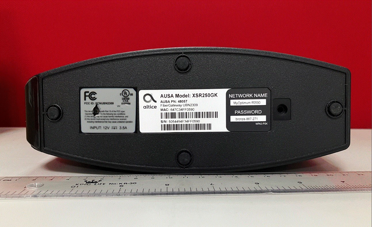
XCNUBN2309
Aug 27, 2023XGS-PON
Equipment Class
DTS - Digital Transmission System
XCNUBN2310
Jul 25, 2023GPON
Equipment Class
NII - Unlicensed National Information Infrastructure TX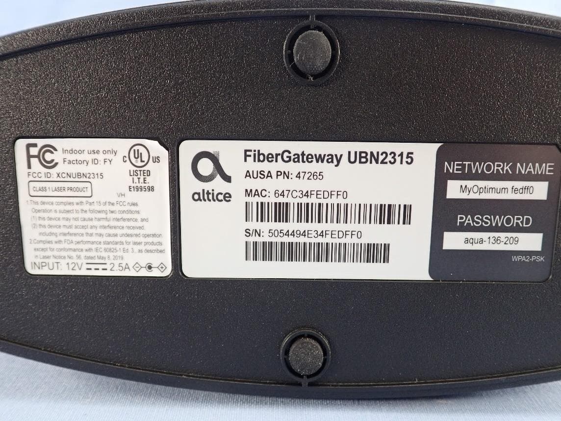
XCNUBN2315
Mar 04, 2023GPON IAD
Equipment Class
6ID - 15E 6 GHz Low Power Indoor Access Point
XCNUBC1340
Feb 01, 2023WeMTA
Equipment Class
6ID - 15E 6 GHz Low Power Indoor Access Point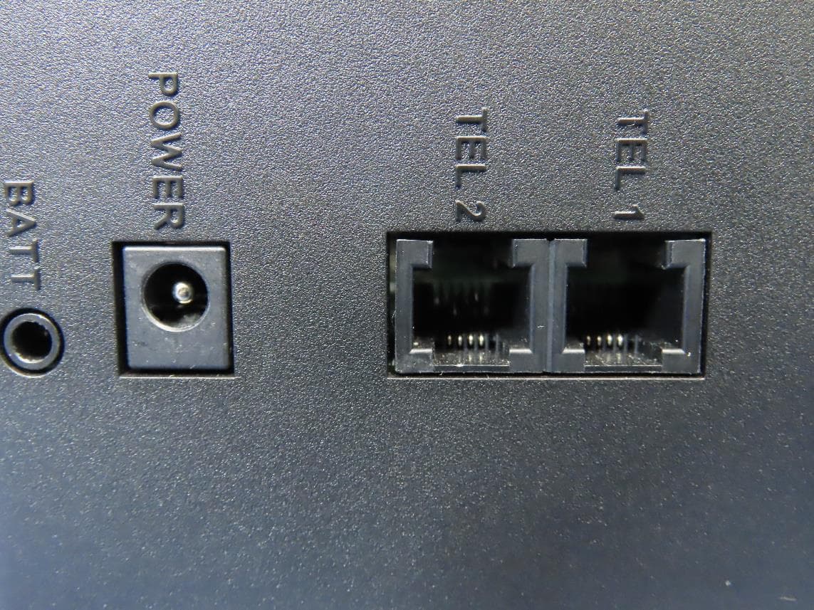
XCNUBC1330
Jan 28, 2023Docsis3.1 advance WiFi 6E Voice Gateway
Equipment Class
6ID - 15E 6 GHz Low Power Indoor Access Point