XCNDVW32DCable Modem
Ubee Interactive Holding Corp. Taiwan Branch
Click to zoom
Application Details
- Equipment Class
- DTS - Digital Transmission System
- Date of Grant
- Jun 09, 2014
- Application Purpose
- Original Equipment
- Date of Application
- Jun 09, 2014
- Equipment Note
- Cable Modem
- Frequency Range
- 2412.00000000 - 2462.00000000
- Country
- Taiwan
Documents & Files
Document Text
Text extracted from the exhibit documents filed with the FCC. Open a document above to read the original.
Users Manual
Ubee Interactive — www.ubeeinteractive.com 1 Ubee DVW32D – Safety and Installation Product Insert v1.0 DVW32D Advanced Wireless Voice Gateway - Safety and Installation Product Insert Federal Communications Commission (FCC) Interference Statement This device has been tested and found to comply with the limits for a Class B digital device, pursuant to Part 15 of the FCC Rules. These limits are designed to provide reasonable protection against harmful interference in a residential installation. This device generates, uses, and can radiate radio frequency energy. If not installed and used in accordance with the instructions, the device may cause harmful interference to radio communications. There is no guarantee, however, that interference will not occur in a particular installation. If the DEVICE causes harmful interference to radio or television reception, which can be determined by turning it off and on, the user can try to correct the interference by one of the following measures: • Increase the separation between the DEVICE and the equipment with which it is interfering (for example, a television or radio). • Connect the DEVICE into an electrical outlet on a different circuit than the interfered device is connected. • Consult the dealer or an experienced radio/TV technician for help. FCC Regulatory Information This device complies with Part 15 of the FCC Rules. Operation is subject to the following two conditions: (1) This device may not cause harmful interference, and (2) this device must accept any interference received, including interference that may cause undesired operation. There is one statement for this product: • The device must carry a label stating “FCC ID: XCNDVW32D.” Ubee Interactive — www.ubeeinteractive.com 2 Ubee DVW32D – Safety and Installation Product Insert v1.0 FCC Caution: Any changes or modifications not expressly approved by the party responsible for compliance could void the user's authority to operate this device. IEEE 802.11b or 802.11g operation of this device in the U.S.A. is firmware-limited to channels 1 through 11. FCC Radiation Exposure Statement: This device complies with FCC radiation exposure limits set forth for an uncontrolled environment. This device should be installed and operated at a minimum distance of 20cm between itself and your body. This device must not be co-located or operating in conjunction with any other antenna or transmitter. Safety Notices Read these instructions carefully before operating the device. It is important to be aware of these safety instructions. Install the device according to these instructions and keep this guide for future reference. 1. Do not use this device in a humid space, in the rain, or near splashing water. 2. Do not install during thunder or lightening storms. 3. Do not cover any ventilation openings in the device case. 4. Do not place the device near heat sources such as radiators or stoves. 5. Clean the device only with a clean, dry cloth. Do not use liquid or chemical cleaners. 6. Avoid static discharge when touching Ubee Interactive — www.ubeeinteractive.com 3 Ubee DVW32D – Safety and Installation Product Insert v1.0 the device by first touching the coaxial connector of the coaxial cable. 7. Installation of the device should include grounding the coaxial cable to the earth at the building entrance per ANSI/NFPA 70 and the National Electrical Code (NEC, in particular, Section 820.93, Grounding of the Outer Conductive Shield of a Coaxial Cable). 8. The device is designed for IT power systems with phase-to-phase voltage at 100-240V. 9. Disconnecting the Device: If the device becomes damaged or encounters some other abnormality, disconnect the power plug from the AC wall outlet immediately. 10. The device should be installed in a location not to exceed the maximum temperature of 40 degrees Celsius (104 degrees Fahrenheit). 11. When the device is placed upright with the aid of the stand, the stand must be fixed at a 90 degree angle to the device. Otherwise, the device will have the risk of tipping over. This is the recommended position for best Wi-Fi performance 12. Keep the device away from Children and Pets 13. Place the device on a cool surface. Failure to do so may result in overheating which can cause extreme damage. 14. Do not modify or attempt to disassemble the device. Use it only according to the instructions. 15. Do not dispose of the device in a trash container. Please recycle. Ubee Interactive — www.ubeeinteractive.com 4 Ubee DVW32D – Safety and Installation Product Insert v1.0 Installation To install this device, follow the procedures below and refer to the following page for a connection diagram. 1. Connect one end of a coaxial cable (not included) to the CABLE port on the device. Connect the other end to a cable splitter or the cable wall outlet. Be sure not to bend or over tighten the cables as this may strain the connector and cause damage. If you plan to connect the device and a television to the same cable wall outlet, you must use a cable line splitter (not included). 2. Connect one end of the supplied Ethernet cable to one of the LAN ports (LAN1 to LAN2) on the device. Connect the other end to the ETHERNET port (ETH1 to ETH2) on a PC. Note: Category 5e or Category 6 Ethernet cables with RJ45 connectors must be used when connecting Ethernet devices to the LAN ports. This ensures Gigabit Ethernet speeds (unless the computer does not support it). 3. Connect one end of an RJ11 phone cable to one of the TEL ports (TEL1 to TEL2) on the device (a port that has been provisioned for voice service as specified by the service provider). Connect the other end to the phone port of the telephone. Note: If voice service is not provisioned through the service provider, telephone service is not available. 4. Connect the power adapter to the POWER port on the device. Plug the other end of the power adapter into the AC wall outlet. Important: Use only the power adapter that is shipped with the device. 540.0…
Text truncated - open the document above for the full version.
Users Manual
Ubee Interactive — www.ubeeinteractive.com 1 Ubee DVW32E – Safety and Installation Product Insert v1.0 DVW32E Advanced Wireless Voice Gateway Safety and Installation Product Insert Federal Communications Commission (FCC) Interference Statement This device has been tested and found to comply with the limits for a Class B digital device, pursuant to Part 15 of the FCC Rules. These limits are designed to provide reasonable protection against harmful interference in a residential installation. This device generates, uses, and can radiate radio frequency energy. If not installed and used in accordance with the instructions, the device may cause harmful interference to radio communications. There is no guarantee, however, that interference will not occur in a particular installation. If the DEVICE causes harmful interference to radio or television reception, which can be determined by turning it off and on, the user can try to correct the interference by one of the following measures: • Increase the separation between the DEVICE and the equipment with which it is interfering (for example, a television or radio). • Connect the DEVICE into an electrical outlet on a different circuit than the interfered device is connected. • Consult the dealer or an experienced radio/TV technician for help. FCC Regulatory Information This device complies with Part 15 of the FCC Rules. Operation is subject to the following two conditions: (1) This device may not cause harmful interference, and (2) this device must accept any interference received, including interference that may cause undesired operation. There is one statement for this product: • The device must carry a label stating “FCC ID: XCNDVW32D.” Ubee Interactive — www.ubeeinteractive.com 2 Ubee DVW32E – Safety and Installation Product Insert v1.0 FCC Caution: Any changes or modifications not expressly approved by the party responsible for compliance could void the user's authority to operate this device. IEEE 802.11b or 802.11g operation of this device in the U.S.A. is firmware-limited to channels 1 through 11. FCC Radiation Exposure Statement: This device complies with FCC radiation exposure limits set forth for an uncontrolled environment. This device should be installed and operated at a minimum distance of 20cm between itself and your body. This device must not be co-located or operating in conjunction with any other antenna or transmitter. Safety Notices Read these instructions carefully before operating the device. It is important to be aware of these safety instructions. Install the device according to these instructions and keep this guide for future reference. 1. Do not use this device in a humid space, in the rain, or near splashing water. 2. Do not install during thunder or lightening storms. 3. Do not cover any ventilation openings in the device case. 4. Do not place the device near heat sources such as radiators or stoves. 5. Clean the device only with a clean, dry cloth. Do not use liquid or chemical cleaners. 6. Avoid static discharge when touching Ubee Interactive — www.ubeeinteractive.com 3 Ubee DVW32E – Safety and Installation Product Insert v1.0 the device by first touching the coaxial connector of the coaxial cable. 7. Installation of the device should include grounding the coaxial cable to the earth at the building entrance per ANSI/NFPA 70 and the National Electrical Code (NEC, in particular, Section 820.93, Grounding of the Outer Conductive Shield of a Coaxial Cable). 8. The device is designed for IT power systems with phase-to-phase voltage at 100 -240V. 9. Disconnecting the Device: If the device becomes damaged or encounters some other abnormality, disconnect the power plug from the AC wall outlet immediately. 10. The device should be installed in a location not to exceed the maximum temperature of 40 degrees Celsius (104 degrees Fahrenheit). 11. When the device is placed upright with the aid of the stand, the stand must be fixed at a 90 degree angle to the device. Otherwise, the device will have the risk of tipping over. This is the recommended position for best Wi-Fi performance 12. Keep the device away from Children and Pets 13. Place the device on a cool surface. Failure to do so may result in overheating which can cause extreme damage. 14. Do not modify or attempt to disassemble the device. Use it only according to the instructions. 15. Do not dispose of the device in a trash container. Please recycle. Ubee Interactive — www.ubeeinteractive.com 4 Ubee DVW32E – Safety and Installation Product Insert v1.0 Installation To install this device, follow the procedures below and refer to the following page for a connection diagram. 1. Connect one end of a coaxial cable (not included) to the CABLE port on the device. Connect the other end to a cable splitter or the cable wall outlet. Be sure not to bend or over tighten the cables as this may strain the connector and cause damage. If you plan to connect the device and a television to the same cable wall outlet, you must use a cable line splitter (not included). 2. Connect one end of the supplied Ethernet cable to one of the LAN ports (LAN1 to LAN2) on the device. Connect the other end to the ETHERNET port (ETH1 to ETH2) on a PC. Note: Category 5e or Category 6 Ethernet cables with RJ45 connectors must be used when connecting Ethernet devices to the LAN ports. This ensures Gigabit Ethernet speeds (unless the computer does not support it). 3. Connect one end of an RJ11 phone cable to one of the TEL ports (TEL1 to TEL2) on the device (a port that has been provisioned for voice service as specified by the service provider). Connect the other end to the phone port of the telephone. Note: If voice service is not provisioned through the service provider, telephone service is not available. 4. Connect the power adapter to the POWER port on the device. Plug the other end of the power adapter into the AC wall outlet. Important: Use only the power adapter that is shipped with the device. 540.00…
Text truncated - open the document above for the full version.
Users Manual
Ubee Interactive — www.ubeeinteractive.com 1 Ubee DDW36A – Safety and Installation Product Insert v1.0 DDW36A Advanced Wireless Gateway - Safety and Installation Product Insert Federal Communications Commission (FCC) Interference Statement This device has been tested and found to comply with the limits for a Class B digital device, pursuant to Part 15 of the FCC Rules. These limits are designed to provide reasonable protection against harmful interference in a residential installation. This device generates, uses, and can radiate radio frequency energy. If not installed and used in accordance with the instructions, the device may cause harmful interference to radio communications. There is no guarantee, however, that interference will not occur in a particular installation. If the DEVICE causes harmful interference to radio or television reception, which can be determined by turning it off and on, the user can try to correct the interference by one of the following measures: • Increase the separation between the DEVICE and the equipment with which it is interfering (for example, a television or radio). • Connect the DEVICE into an electrical outlet on a different circuit than the interfered device is connected. • Consult the dealer or an experienced radio/TV technician for help. FCC Regulatory Information This device complies with Part 15 of the FCC Rules. Operation is subject to the following two conditions: (1) This device may not cause harmful interference, and (2) this device must accept any interference received, including interference that may cause undesired operation. There is one statement for this product: • The device must carry a label stating “FCC ID: XCNDVW32D.” Ubee Interactive — www.ubeeinteractive.com 2 Ubee DDW36A – Safety and Installation Product Insert v1.0 FCC Caution: Any changes or modifications not expressly approved by the party responsible for compliance could void the user's authority to operate this device. IEEE 802.11b or 802.11g operation of this device in the U.S.A. is firmware-limited to channels 1 through 11. FCC Radiation Exposure Statement This device complies with FCC radiation exposure limits set forth for an uncontrolled environment. This device should be installed and operated at a minimum distance of 20cm between itself and your body. This device must not be co-located or operating in conjunction with any other antenna or transmitter. Safety Notices Read these instructions carefully before operating the device. It is important to be aware of these safety instructions. Install the device according to these instructions and keep this guide for future reference. 1. Do not use this device in a humid space, in the rain, or near splashing water. 2. Do not install during thunder or lightening storms. 3. Do not cover any ventilation openings in the device case. 4. Do not place the device near heat sources such as radiators or stoves. 5. Clean the device only with a clean, dry cloth. Do not use liquid or chemical cleaners. Ubee Interactive — www.ubeeinteractive.com 3 Ubee DDW36A – Safety and Installation Product Insert v1.0 6. Avoid static discharge when touching the device by first touching the coaxial connector of the coaxial cable. 7. Installation of the device should include grounding the coaxial cable to the earth at the building entrance per ANSI/NFPA 70 and the National Electrical Code (NEC, in particular, Section 820.93, Grounding of the Outer Conductive Shield of a Coaxial Cable). 8. The device is designed for IT power systems with phase-to-phase voltage at 100-240V. 9. Disconnecting the Device: If the device becomes damaged or encounters some other abnormality, disconnect the power plug from the AC wall outlet immediately. 10. The device should be installed in a location not to exceed the maximum temperature of 40 degrees Celsius (104 degrees Fahrenheit). 11. When the device is placed upright with the aid of the stand, the stand must be fixed at a 90 degree angle to the device. Otherwise, the device will have the risk of tipping over. This is the recommended position for best Wi-Fi performance 12. Keep the device away from Children and Pets 13. Place the device on a cool surface. Failure to do so may result in overheating which can cause extreme damage. 14. Do not modify or attempt to disassemble the device. Use it only according to the instructions. 15. Do not dispose of the device in a trash container. Please recycle. Ubee Interactive — www.ubeeinteractive.com 4 Ubee DDW36A – Safety and Installation Product Insert v1.0 Installation To install this device, follow the procedures below and refer to the following page for a connection diagram. 1. Connect one end of a coaxial cable (not included) to the CABLE port on the device. Connect the other end to a cable splitter or the cable wall outlet. Be sure not to bend or over tighten the cables as this may strain the connector and cause damage. If you plan to connect the device and a television to the same cable wall outlet, you must use a cable line splitter (not included). 2. Connect one end of the supplied Ethernet cable to one of the LAN ports (LAN1 to LAN2) on the device. Connect the other end to the ETHERNET port (ETH1 to ETH2) on a PC. Note: Category 5e or Category 6 Ethernet cables with RJ45 connectors must be used when connecting Ethernet devices to the LAN ports. This ensures Gigabit Ethernet speeds (unless the computer does not support it). 3. Connect the power adapter to the POWER port on the device. Plug the other end of the power adapter into the AC wall outlet. Important: Use only the power adapter that is shipped with the device. 540.00955.015 Ubee Interactive — www.ubeeinteractive.com 5 Ubee DDW36A – Safety and Installation Product Insert v1.0 Wall-Mount Installation You can mount the device on a wall using the 2 mounting brackets on the bottom of the device. We recommend that you use two round or pan head screws. 1. Install two screws horizontally apart on a wall using the measurement …
Text truncated - open the document above for the full version.
External Photos
Page 1 CONSTRUCTION PHOTOS OF EUT Sample 1 & Sample 3 Page 2 Page 3 Page 4 Page 5 Page 6 Page 7 Sample 2 & Sample 4 Page 8 Sample 5 & Sample 6 Page 9 Page 10 Page 11
ID Label/Location Info
0.02013.12.21 U10C091.81 PTT Label 500.01679.005 Yanli Yu Cun Zhou Cun Factory ID list =========================== (100544-836) FUHONG PRECISION COMPONENT (BAC GIANG) LTD DINH TRAM INDUSTRY PARK VIET YEN DISTRICT VIET NAM Factory ID: Y =========================== (100568-850) NANNING FUGUI PRECISION INDUSTRIAL CO LTD 18 ZONGBU RD NEW & HIGH-TECH INDUSTRIAL DEVELOPMENT ZONE NANNING GUANGXI CHINA Factory ID: N ============================ (128685-001) AMBIT MICROSYSTEMS (SHANGHAI) LTD 1925 NAN-LE RD SONGJIANG EXPORT PROCESSING ZONE SHANGHAI 201613 CHINA Factory ID: E ================================ (223850-001) HONG FU JIN PRECISION INDUSTRY (SHENZHEN) CO LTD 10TH YOUSONG INDUSTRIAL DISTRICT 2ND DONGHUAN RD NO 2 BAO'AN LONGHUA TOWN SHENZHEN 518109 GUANGDONG CHINA Factory ID: F ================================== PTT label 500.01679.005 42*40mm Scale:1/1 Vendor Provide Foxconn printing Arial, 7pt "X": UL Factory ID, please see the list, if the manufacturer is not in the list, please confirm with PM or Compliance Engineer. Foxconn printing Arial, 5pt I.T.E. E199598 8G92 Vendor code NOTES: 1.Material: #50 Mylar + 25# PET(matte, printable) 2.Adhesive: 3.Adhesive thickness : 50#Mylar: 0.030+/-0.003mm 25#PET: 0.018+/-0.003mm 4.Printing Color:Black 5.Background: White 6.Liner:Glassine release paper 7.Packaging Style: Reel 8.The part must be RoHS compliant 9.Mark UL logo and vender code on out packing. 12.Holding power():>/=10 hr/Kg/20mm 2 10.Adhesion to steel(180 ): >/=1.22 Kg/inch 11.Initial Tack(): >/=6 #/boll o Model name: DVW32D FCC ID: XCNDVW32D This device complies with part 15 of the FCC Rules. Factory ID: X I.T.E. E199598 8G92 packaging style Input: 12V 2A Ubee Part No.: DVW32D0BU Model name: DVW32D FCC ID: XCNDVW32D This device complies with part 15 of the FCC Rules. I.T.E. E199598 8G92 Input: 12V 2A 0.1 2014.03.04 update PTT label Cun
Internal Photos
Page 12 Sample 1 & Sample 3 Page 13 Page 14 Page 15 Page 16 Sample 2 & Sample 4 Page 17 Page 18 Page 19 Sample 5 & Sample 6 Page 20 Page 21 Page 22
RF Exposure Info
Report No.: SA140505C01 1 of 6 Report Format Version 5.0.0 RF EXPOSURE REPORT REPORT NO.: SA140505C01 MODEL NO.: DVW32D FCC ID: XCNDVW32D RECEIVED: May 05, 2014 TESTED: May 14 ~ May 22, 2014 ISSUED: May 23, 2014 APPLICANT: Ubee Interactive Corp. ADDRESS: 10F-1, No. 5, Taiyuan 1st St. Jhubei Ci, Hsinchu County 302, Taiwan, R.O.C. ISSUED BY: Bureau Veritas Consumer Products Services (H.K.) Ltd., Taoyuan Branch LAB ADDRESS: No. 47, 14th Ling, Chia Pau Vil., Lin Kou Dist., New Taipei City, Taiwan, R.O.C. TEST LOCATION: No. 19, Hwa Ya 2nd Rd, Wen Hwa Tsuen, Kwei Shan Hsiang, Taoyuan Hsien 333, Taiwan, R.O.C. This report is for your exclusive use. Any copying or replication of this report to or for any other person or entity, or use of our name or trademark, is permitted only with our prior written permission. This report sets forth our findings solely with respect to the test samples identified herein. The results set forth in this report are not indicative or representative of the quality or characteristics of the lot from which a test sample was taken or any similar or identical product unless specifically and expressly noted. Our report includes all of the tests requested by you and the results thereof based upon the information that you provided to us. You have 60 days from date of issuance of this report to notify us of any material error or omission caused by our negligence, provided, however, that such notice shall be in writing and shall specifically address the issue you wish to raise. A failure to raise such issue within the prescribed time shall constitute your unqualified acceptance of the completeness of this report, the tests conducted and the correctness of the report contents. Unless specific mention, the uncertainty of measurement has been explicitly taken into account to declare the compliance or non-com pliance to the specification. Report No.: SA140505C01 2 of 6 Report Format Version 5.0.0 TABLE OF CONTENTS RELEASE CONTROL RECORD ................................................................................................................ 3 1. CERTIFICATION ............................................................................................................................ 4 2. RF EXPOSURE ............................................................................................................................. 5 2.1 LIMITS FOR MAXIMUM PERMISSIBLE EXPOSURE (MPE) ....................................................... 5 2.2 MPE CALCULATION FORMULA .................................................................................................. 5 2.3 CLASSIFICATION.......................................................................................................................... 5 2.4 CALCULATION RESULT OF MAXIMUM CONDUCTED POWER ................................................ 6 Report No.: SA140505C01 3 of 6 Report Format Version 5.0.0 RELEASE CONTROL RECORD ISSUE NO. REASON FOR CHANGE DATE ISSUED SA140505C01 Original release May 23, 2014 Report No.: SA140505C01 4 of 6 Report Format Version 5.0.0 1. CERTIFICATION PRODUCT: Cable Modem MODEL NO.: DVW32D BRAND: Ubee APPLICANT: Ubee Interactive Corp. TESTED: May 14 ~ May 22, 2014 TEST SAMPLE: ENGINEERING SAMPLE STANDARDS: FCC Part 2 (Section 2.1091) FCC OET Bulletin 65, Supplement C (01-01) IEEE C95.1 The above equipment (model: DVW32D) has been tested by Bureau Veritas Consumer Products Services (H.K.) Ltd., Taoyuan Branch, and found compliance with the requirement of the above standards. The test record, data evaluation & Equipment Under Test (EUT) configurations represented herein are true and accurate accounts of the measurements of the sample’s EMC characteristics under the conditions specified in this report. PREPARED BY : , DATE :May 23, 2014 Ivy Lin / Specialist APPROVED BY : , DATE :May 23, 2014 Ken Liu / Senior Manager Report No.: SA140505C01 5 of 6 Report Format Version 5.0.0 2. RF EXPOSURE 2.1 LIMITS FOR MAXIMUM PERMISSIBLE EXPOSURE (MPE) FREQUENCY RANGE (MHz) ELECTRIC FIELD STRENGTH (V/m) MAGNETIC FIELD STRENGTH (A/m) POWER DENSITY (mW/cm 2 ) AVERAGE TIME (minutes) LIMITS FOR GENERAL POPULATION / UNCONTROLLED EXPOSURE 300-1500 ... ... F/1500 30 1500-100,000 ... ... 1.0 30 F = Frequency in MHz 2.2 MPE CALCULATION FORMULA Pd = (Pout*G) / (4*pi*r 2 ) where Pd = power density in mW/cm 2 Pout = output power to antenna in mW G = gain of antenna in linear scale Pi = 3.1416 R = distance between observation point and center of the radiator in cm 2.3 CLASSIFICATION The antenna of this product, under normal use condition, is at least 20cm away from the body of the user. So, this device is classified as Mobile Device. Report No.: SA140505C01 6 of 6 Report Format Version 5.0.0 2.4 CALCULATION RESULT OF MAXIMUM CONDUCTED POWER FREQUENCY BAND (MHz) MAX POWER (dBm) ANTENNA GAIN (dBi) DISTANCE (cm) POWER DENSITY (mW/cm 2 ) LIMIT (mW/cm 2 ) 2412-2462 21.86 5.89 20 0.119 1 NOTE: Directional gain = 10 log[(10 G1 /20 + 10 G2 /20 + ... + 10 GN /20 ) 2 /N ANT ]= 5.89 ---END---
Test Report
Report No.: RF140505C01 1 of 59 Report Format Version 5.2.0 FCC TEST REPORT REPORT NO.: RF140505C01 MODEL NO.: DVW32D FCC ID: XCNDVW32D RECEIVED: May 05, 2014 TESTED: May 14 ~ May 22, 2014 ISSUED: May 23, 2014 APPLICANT: Ubee Interactive Corp. ADDRESS: 10F-1, No. 5, Taiyuan 1st St. Jhubei Ci, Hsinchu County 302, Taiwan, R.O.C. ISSUED BY: Bureau Veritas Consumer Products Services (H.K.) Ltd., Taoyuan Branch LAB ADDRESS: No. 47, 14th Ling, Chia Pau Vil., Lin Kou Dist., New Taipei City, Taiwan, R.O.C. TEST LOCATION: No. 19, Hwa Ya 2nd Rd, Wen Hwa Tsuen, Kwei Shan Hsiang, Taoyuan Hsien 333, Taiwan, R.O.C. This report is for your exclusive use. Any copying or replication of this report to or for any other person or entity, or use of our name or trademark, is permitted only with our prior written permission. This report sets forth our findings solely with respect to the test samples identified herein. The results set forth in this report are not indicative or representative of the quality or characteristics of the lot from which a test sample was taken or any similar or identical product unless specifically and expressly noted. Our report includes all of the tests requested by you and the results thereof based upon the information that you provided to us. You have 60 days from date of issuance of this report to notify us of any material error or omission caused by our negligence, provided, however, that such notice shall be in writing and shall specifically address the issue you wish to raise. A failure to raise such issue within the prescribed time shall constitute your unqualified acceptance of the completeness of this report, the tests conducted and the correctness of the report contents. Unless specific mention, the uncertainty of measurement has been explicitly taken into account to declare the compliance or non-com pliance to the specification. This report should not be used by the client to claim product certification, approval, or endorsement by TAF or any government agencies. Report No.: RF140505C01 2 of 59 Report Format Version 5.2.0 TABLE OF CONTENTS RELEASE CONTROL RECORD ................................................................................................................ 4 1. CERTIFICATION ............................................................................................................................ 5 2. SUMMARY OF TEST RESULTS ................................................................................................... 6 2.1 MEASUREMENT UNCERTAINTY ................................................................................................ 6 3. GENERAL INFORMATION ............................................................................................................ 7 3.1 GENERAL DESCRIPTION OF EUT .............................................................................................. 7 3.2 DESCRIPTION OF TEST MODES ................................................................................................ 9 3.2.1 TEST MODE APPLICABILITY AND TESTED CHANNEL DETAIL .............................................. 10 3.3 DUTY CYCLE OF TEST SIGNAL ................................................................................................ 12 3.4 DESCRIPTION OF SUPPORT UNITS ........................................................................................ 13 3.4.1 CONFIGURATION OF SYSTEM UNDER TEST ......................................................................... 14 3.5 GENERAL DESCRIPTION OF APPLIED STANDARDS ............................................................. 15 4. TEST TYPES AND RESULTS ..................................................................................................... 16 4.1 RADIATED EMISSION AND BANDEDGE MEASUREMENT ..................................................... 16 4.1.1 LIMITS OF RADIATED EMISSION AND BANDEDGE MEASUREMENT ................................... 16 4.1.2 TEST INSTRUMENTS ................................................................................................................. 17 4.1.3 TEST PROCEDURES ................................................................................................................. 18 4.1.4 DEVIATION FROM TEST STANDARD ....................................................................................... 18 4.1.5 TEST SETUP ............................................................................................................................... 19 4.1.6 EUT OPERATING CONDITIONS ................................................................................................ 20 4.1.7 TEST RESULTS .......................................................................................................................... 21 4.2 CONDUC…
Text truncated - open the document above for the full version.
Contact Information
Applicant
Lily Liu(Manager)
Test Firm
Bureau Veritas CPS (H.K.) Ltd., Taoyuan BranchRichard Chen
Technical Specifications
| # | Rule Parts | Frequency Range | Power Output |
|---|---|---|---|
| 1 | 15C | 2.41 GHz - 2.46 GHz | 153.00 mW |
Other Applications from Ubee Interactive Holding Corp. Taiwan Branch
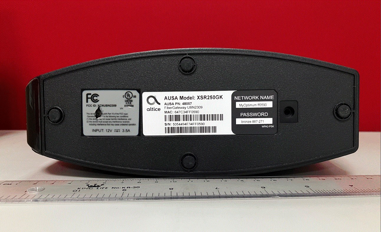
XCNUBN2309
Aug 27, 2023XGS-PON
Equipment Class
DTS - Digital Transmission System
XCNUBN2310
Jul 25, 2023GPON
Equipment Class
NII - Unlicensed National Information Infrastructure TX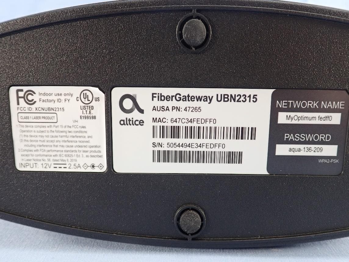
XCNUBN2315
Mar 04, 2023GPON IAD
Equipment Class
6ID - 15E 6 GHz Low Power Indoor Access Point
XCNUBC1340
Feb 01, 2023WeMTA
Equipment Class
6ID - 15E 6 GHz Low Power Indoor Access Point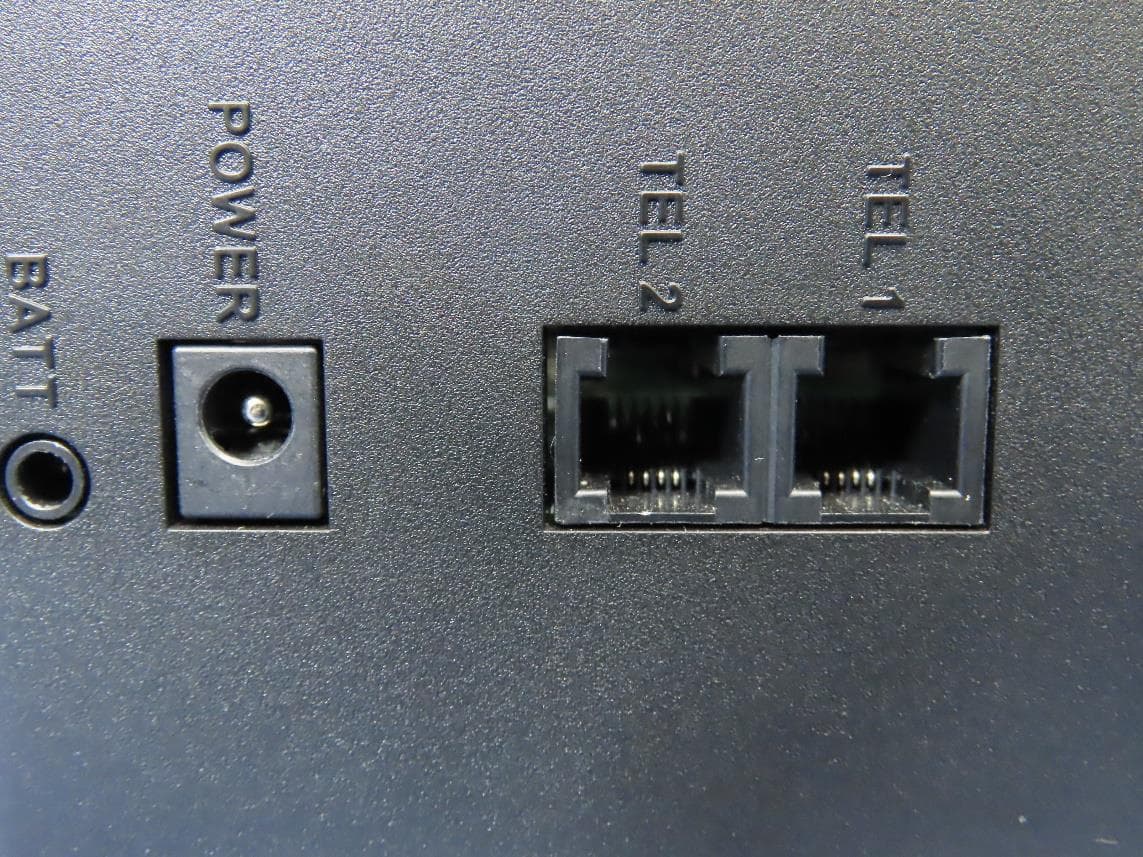
XCNUBC1330
Jan 28, 2023Docsis3.1 advance WiFi 6E Voice Gateway
Equipment Class
6ID - 15E 6 GHz Low Power Indoor Access Point