XCNUBC1326Wireless eMTA
Ubee Interactive Holding Corp. Taiwan Branch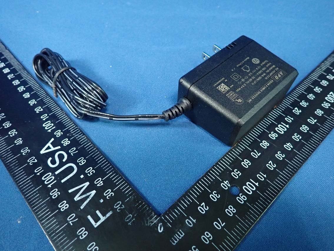
Click to zoom
Application Details
- Equipment Class
- DTS - Digital Transmission System
- Date of Grant
- Mar 11, 2020
- Application Purpose
- Original Equipment
- Date of Application
- Mar 11, 2020
- Equipment Note
- Wireless eMTA
- Frequency Range
- 2412.00000000 - 2462.00000000
- Country
- Taiwan
Documents & Files
Document Text
Text extracted from the exhibit documents filed with the FCC. Open a document above to read the original.
Users Manual
UBC1326AA00 DOCSIS 3.1 Wireless eMTA Quick Installation Guide UBC1326AA00 D3.1 Wireless eMTA Quick Installation Guide Subscriber Grounding the Device: Install the cable modem to include grounding the coaxial cable to the earth as close as practical to the building entrance per ANSI/NFPA 70 and the National Electrical Code (NEC, in particular, Section 820.93, Grounding of the Outer Conductive Shield of a Coaxial Cable). The device is designed for IT power systems with phase-to-phase voltage at 120V. This unit requires a 100-240V, 50/60Hz power adapter. The power adapter must be keyed for proper polarization, and must be fully inserted to contact the back of the power connector port to ensure snug connection. Do NOT use any other power adapter. Disconnecting the Device: If the cable modem becomes damaged or encounters some other abnormality, disconnect the power plug from the AC wall outlet immediately. Temperature and Altitude: Install the device in a location not to exceed the maximum temperature of 104°F (40°C). Regular operating altitude is 2000 m, and maximum operating altitude is 4500 m. • SAFETY NOTICES • PREPARING FOR INSTALLATION ✓ Locate the RF (coaxial) cable connector on the wall. ✓ Verify the power outlet is working and is wired correctly. ✓ Place your cable modem within a proper distance from the outlet. To connect a modem and a television to the same wall outlet, you must use a cable line splitter (not included). 2.Connect an Ethernet cable (supplied) to one of the LAN (Ethernet) ports on the back panel of the modem and connect the other end to the Ethernet port of a computer. Use a Category 5e or Category 6 Ethernet cable with RJ-45 connectors to ensure Gigabit Ethernet speeds (when the computer supports it). 3.Connect an RJ-11 phone cable (not supplied) to the TEL (telephone) port on the modem (when provisioned for voice service as specified by the service provider), and connect the other end to the phone port of the telephone. If voice service is not provisioned through the service provider, telephone service is not available. 4.Connect the power adapter (supplied) to the PWR (power) port. Connect the other end to a power outlet. 1 UBC1326AA00 Wireless Voice Gateway RJ-45 Analog Phone RJ-11 Cable/RF Device must be installed vertically using the included leg stands to obtain optimum wireless performance. Connect computers or Ethernet enabled devices (wireless switch or router). A PC should be connected for initial device installation and configuration. 2 1 3 4 1.Connect the included leg stands to the bottom of the device to enable the modem to be installed vertically. Connect the coaxial cable (not supplied) to the DS/US (cable) connector on the rear panel of the modem and connect the other end to the cable wall outlet. Do not bend or over tighten the cable, as this may strain the connector and cause damage. • INSTALLING THE UBC1326AA00 • DEVICE WALL MOUNT INSTRUCTIONS 2 Label Millimeters (mm) A7.2 +/- 0.5 B2.6 +/- 0.15 C19.0 +/- 1.2 D3~4 UBC1326AA00 Quick Installation Guide 5.Separate the wall mounting pieces. Mount the top and bottom leg stand pieces (Figure 1) onto the UBC1326AA00 as shown in Figure 2. 6.You can now mount the UBC1326AA00 onto the wall using the screws installed in Step 4. 2.Fit the 2 leg stand pieces together with the wall mount template as represented in the graphic to the right. 3.Place this on the wall and use it as a template to mark the wall for the appropriate placement of the screws. 4.Install the 4 screws on the wall (158 mm or 6.2 inches apart). NOTE: The screws should protrude from the wall so you can fit the device between the head of the screws and the wall. If you install the screws in drywall, use hollow wall anchors to ensure the unit does not pull away from the wall due to prolonged strain from the cable and power connectors. You can mount the UBC1326AA00 on a wall by following the steps below: 1.You will need 4 round or pan head screws with the following measurements: Figure 1 Figure 2 • FEDERAL COMMUNICATION COMMISSION (FCC) INTERFERENCE STATEMENT This device complies with Part 15 of the FCC Rules. Operation is subject to the following two conditions: (1) This device may not cause harmful interference, and (2) this device must accept any interference received, including interference that may cause undesired operation. This equipment has been tested and found to comply with the limits for a Class B digital device, pursuant to Part 15 of the FCC Rules. These limits are designed to provide reasonable protection against harmful interference in a residential installation. This equipment generates, uses and can radiate radio frequency energy and, if not installed and used in accordance with the instructions, may cause harmful interference to radio communications. However, there is no guarantee that interference will not occur in a particular installation. If this equipment does cause harmful interference to radio or television reception, which can be determined by turning the equipment off and on, the user is encouraged to try to correct the interference by one of the following measures: •Reorient or relocate the receiving antenna. •Increase the separation between the equipment and receiver. •Connect the equipment into an outlet on a circuit different from that to which the receiver is connected. •Consult the dealer or an experienced radio/TV technician for help. 3 UBC1326AA00 Quick Installation Guide 5GHz Wireless Statement: For operation within the 5.15~5.25GHz and 5.47~5.725GHz frequency ranges, this device is restricted to indoor environments. This device meets all the other requirements specified in Part 15E, Section 15.407 of the FCC Rules. FCC Caution: Any changes or modifications not expressly approved by the party responsible for compliance could void the user's authority to operate this equipment. This transmitter must not be co-located or operating in conjunction with any other antenna or transmitter. Radiation Exposure Statement:…
Text truncated - open the document above for the full version.
External Photos
Reference No.: 191105E04-1 Page No. 1 / 5 Report No.: {report no} CONSTRUCTION PHOTOS OF EUT Reference No.: 191105E04-1 Page No. 2 / 5 Report No.: {report no} Reference No.: 191105E04-1 Page No. 3 / 5 Report No.: {report no} Reference No.: 191105E04-1 Page No. 4 / 5 Report No.: {report no} Reference No.: 191105E04-1 Page No. 5 / 5 Report No.: {report no}
ID Label/Location Info
(Fig. 1) FCC ID: XCNUBC1326 FCC LABEL LOCATION The label will be permanently affixed at a conspicuous location on the device. Label
ID Label/Location Info
PTT label /U10C149.00/00/2 OF 10 29.5 38.5 1.5 3 32.5 26.5 R 2 FCC ID: XCNUBC1326 2019/12/03 500.02478.005 Model Name: UBC1326 Factory ID: U FCC ID: XCNUBC1326 Model Name: UBC1326 Factory ID: U U10C149.00
Internal Photos
Reference No.: 191105E04-2 Page No. 1 / 21 Report No.: {report no} CONSTRUCTION PHOTOS OF EUT Reference No.: 191105E04-2 Page No. 2 / 21 Report No.: {report no} Reference No.: 191105E04-2 Page No. 3 / 21 Report No.: {report no} Reference No.: 191105E04-2 Page No. 4 / 21 Report No.: {report no} Reference No.: 191105E04-2 Page No. 5 / 21 Report No.: {report no} Reference No.: 191105E04-2 Page No. 6 / 21 Report No.: {report no} Reference No.: 191105E04-2 Page No. 7 / 21 Report No.: {report no} Reference No.: 191105E04-2 Page No. 8 / 21 Report No.: {report no} Reference No.: 191105E04-2 Page No. 9 / 21 Report No.: {report no} Reference No.: 191105E04-2 Page No. 10 / 21 Report No.: {report no} Reference No.: 191105E04-2 Page No. 11 / 21 Report No.: {report no} Reference No.: 191105E04-2 Page No. 12 / 21 Report No.: {report no} Reference No.: 191105E04-2 Page No. 13 / 21 Report No.: {report no} Reference No.: 191105E04-2 Page No. 14 / 21 Report No.: {report no} WiFi 1 Antenna Reference No.: 191105E04-2 Page No. 15 / 21 Report No.: {report no} Reference No.: 191105E04-2 Page No. 16 / 21 Report No.: {report no} WiFi 2 Antenna Reference No.: 191105E04-2 Page No. 17 / 21 Report No.: {report no} Reference No.: 191105E04-2 Page No. 18 / 21 Report No.: {report no} WiFi 3 Antenna Reference No.: 191105E04-2 Page No. 19 / 21 Report No.: {report no} Reference No.: 191105E04-2 Page No. 20 / 21 Report No.: {report no} WiFi 4 Antenna Reference No.: 191105E04-2 Page No. 21 / 21 Report No.: {report no}
RF Exposure Info
Report No.: SA191105E04 Page No. 1 / 6 Report Format Version: 6.1.1 RF Exposure Report Report No.: SA191105E04 FCC ID: XCNUBC1326 Test Model: UBC1326 Received Date: July 09, 2019 Test Date: Feb. 07, 2020 Issued Date: Mar. 06, 2020 Applicant: Ubee Interactive Corp. Address: 10F-1, No. 5, Taiyuan 1st St. Zhubei City, Hsinchu County 302, Taiwan , R.O.C. Issued By: Bureau Veritas Consumer Products Services (H.K.) Ltd., Taoyuan Branch Hsin Chu Laboratory Lab Address: E-2, No.1, Li Hsin 1st Road, Hsinchu Science Park, Hsinchu City 300, Taiwan. Test Location: E-2, No.1, Li Hsin 1st Road, Hsinchu Science Park, Hsinchu City 300, Taiwan. FCC Registration / Designation Number: 723255 / TW2022 This report is for your exclusive use. Any copying or replication of this report to or for any other person or entity, or use of our name or trademark, is permitted only with our prior written permission. This report sets forth our findings solely with respect to the test samples identified herein. The results set forth in this report are not indicative or representative of the quality or characteristics of the lot from which a test sample was taken or any similar or identical product unless specifically and expressly noted. Our report includes all of the tests requested by you and the results thereof based upon the information that you provided to us. You have 60 days from date of issuance of this report to notify us of any material error or omission caused by our negligence, provided, however, that such notice shall be in writing and shall specifically address the issue you wish to raise. A failure to raise such issue within the prescribed time shall constitute your unqualified acceptance of the completeness of this report, the tests conducted and the correctness of the report contents. Unless specific mention, the uncertainty of measurement has been explicitly taken into account to declare the compliance or non-compliance to the specification. The report must not be used by the client to claim product certification, approval, or endorsement by any government agencies. Report No.: SA191105E04 Page No. 2 / 6 Report Format Version: 6.1.1 Table of Contents Release Control Record .................................................................................................................................. 3 1 Certificate of Conformity ...................................................................................................................... 4 2 RF Exposure .......................................................................................................................................... 5 2.1 Limits For Maximum Permissible Exposure (MPE) ............................................................................. 5 2.2 MPE Calculation Formula ................................................................................................................... 5 2.3 Classification ....................................................................................................................................... 5 2.4 Antenna Gain ...................................................................................................................................... 5 2.5 Calculation Result of Maximum Conducted Power ............................................................................. 6 Report No.: SA191105E04 Page No. 3 / 6 Report Format Version: 6.1.1 Release Control Record Issue No. Description Date Issued SA191105E04 Original release. Mar. 06, 2020 Report No.: SA191105E04 Page No. 4 / 6 Report Format Version: 6.1.1 1 Certificate of Conformity Product: Wireless eMTA Brand: Ubee Test Model: UBC1326 Applicant: Ubee Interactive Corp. Test Date: Feb. 07, 2020 Standards: FCC Part 2 (Section 2.1091) IEEE C95.3-2002 References Test Guidance: KDB 447498 D01 General RF Exposure Guidance v06 The above equipment has been tested by Bureau Veritas Consumer Products Services (H.K.) Ltd., Taoyuan Branch, and found compliance with the requirement of the above standards. The test record, data evaluation & Equipment Under Test (EUT) configurations represented herein are true and accurate accounts of the measurements of the sample’s EMC characteristics under the conditions specified in this report. Prepared by : , Date: Mar. 06, 2020 Claire Kuan / Specialist Approved by : , Date: Mar. 06, 2020 Clark Lin / Technical Manager Report No.: SA191105E04 Page No. 5 / 6 Report Format Version: 6.1.1 2 RF Exposure 2.1 Limits for Maximum Permissible Exposure (MPE) Frequency Range (MHz) Electric Field Strength (V/m) Magnetic Field Strength (A/m) Power Density (mW/cm 2 ) Average Time (minutes) Limits For General Population / Uncontrolled Exposure 0.3-1.34 614 1.63 (100)* 30 1.34-30 824/f 2.19/f (180/f 2 )* 30 30-300 27.5 0.073 0.2 30 300-1500 ... ... f/1500 30 1500-100,000 ... ... 1.0 30 f = Frequency in MHz ; *Plane-wave equivalent power density 2.2 MPE Calculation Formula Pd = (Pout*G) / (4*pi*r 2 ) where Pd = power density in mW/cm 2 Pout = output power to antenna in mW G = gain of antenna in linear scale Pi = 3.1416 R = distance between observation point and center of the radiator in cm 2.3 Classification The antenna of this product, under normal use condition, is at least 42 cm away from the body of the user. So, this device is classified as Mobile Device. 2.4 Antenna Gain Antenna NO. RF Chain NO. Antenna Net Gain(dBi) Frequency range Antenna Type Connector Type Cable Length WiFi 1 Chain1/2 3.9/4.14 2.4GHz/5GHz PCB i-pex(MHF) 155mm WiFi 2 Chain2/1 3.97/4.84 2.4GHz/5GHz PCB i-pex(MHF) 87mm WiFi 3 Chain0/3 3.9/3.85 2.4GHz/5GHz PCB i-pex(MHF) 75mm WiFi 4 Chain3/0 3.08/3.59 2.4GHz/5GHz PCB i-pex(MHF) 100mm Report No.: SA191105E04 Page No. 6 / 6 Report Format Version: 6.1.1 2.5 Calculation Result of Maximum Conducted Power Operation Mode Evaluation Frequency (MHz) Max Power (mW) Antenna Gain (dBi) Distance (cm) Power Density (mW/cm 2 ) Limit (mW/cm 2 ) WLAN 2.4GHz 2437 985.542 9.74 42 0.41876 1 WLAN U-NII-1 5230 759.…
Text truncated - open the document above for the full version.
Test Report
Report No.: RF191105E04-2 Page No. 1 / 27 Report Format Version: 6.1.1 Reference No.: Supplemental “Transmit Simultaneously” Test Report Report No.: RF191105E04-2 FCC ID: XCNUBC1326 Test Model: UBC1326 Received Date: July 09, 2019 Test Date: Nov. 11 2019 to Feb. 07, 2020 Issued Date: Mar. 06, 2020 Applicant: Ubee Interactive Corp. Address: 10F-1, No. 5, Taiyuan 1st St. Zhubei City, Hsinchu County 302, Taiwan , R.O.C. Issued By: Bureau Veritas Consumer Products Services (H.K.) Ltd., Taoyuan Branch Hsin Chu Laboratory Lab Address: E-2, No.1, Li Hsin 1st Road, Hsinchu Science Park, Hsinchu City 300, Taiwan Test Location: E-2, No.1, Li Hsin 1st Road, Hsinchu Science Park, Hsinchu City 300, Taiwan FCC Registration / Designation Number: 723255 / TW2022 This report is for your exclusive use. Any copying or replication of this report to or for any other person or entity, or use of our name or trademark, is permitted only with our prior written permission. This report sets forth our findings solely with respect to the test samples identified herein. The results set forth in this report are not indicative or representative of the quality or characteristics of the lot from which a test sample was taken or any similar or identical product unless specifically and expressly noted. Our report includes all of the tests requested by you and the results thereof based upon the information that you provided to us. You have 60 days from date of issuance of this report to notify us of any material error or omission caused by our negligence, provided, however, that such notice shall be in writing and shall specifically address the issue you wish to raise. A failure to raise such issue within the prescribed time shall constitute your unqualified acceptance of the completeness of this report, the tests conducted and the correctness of the report contents. Unless specific mention, the uncertainty of measurement has been explicitly taken into account to declare the compliance or non-compliance to the specification. This report should not be used by the client to claim product certification, approval, or endorsement by TAF or any government agencies. Report No.: RF191105E04-2 Page No. 2 / 27 Report Format Version: 6.1.1 Reference No.: Table of Contents Release Control Record .................................................................................................................................. 3 1 Certificate of Conformity ...................................................................................................................... 4 2 Summary of Test Results ..................................................................................................................... 5 2.1 Measurement Uncertainty ................................................................................................................... 5 2.2 Modification Record ............................................................................................................................ 5 3 General Information .............................................................................................................................. 6 3.1 General Description of EUT ................................................................................................................ 6 3.1.1 Test Mode Applicability and Tested Channel Detail ............................................................................. 8 3.2 Description of Support Units ............................................................................................................. 10 3.2.1 Configuration of System under Test ................................................................................................... 11 4 Test Types and Results ...................................................................................................................... 12 4.1 Radiated Emission and Bandedge Measurement ............................................................................. 12 4.1.1 Limits of Radiated Emission and Bandedge Measurement .............................................................. 12 4.1.2 Test Instruments ................................................................................................................................ 13 4.1.3 Test Procedures ................................................................................................................................. 14 4.1.4 Deviation from Test Standard ............................................................................................................ 14 4.1.5 Test Setup .......................................................................................................................................... 15 4.1.6 EUT Operating Conditions ................................................................................................................. 16 4.1.7 Test Results ....................................................................................................................................... 17 4.2 Conducted Emission Measurement .................................................................................................. 20 4.2.1 Limits of Conducted Emission Measurement .................................................................................... 20 4.2.2 Test Instruments ................................................................................................................................ 20 4.2.3 Test Procedures ................................................................................................................................. 21 4.2.4 Deviation from Test Standard ............................................................................................................ 21 4.2.5 Test Setup .......................................................................................................................................... 21 4.2.6 EUT Operating Conditions .......................…
Text truncated - open the document above for the full version.
Test Report
Report No.: RF191105E04 Page No. 1 / 73 Report Format Version: 6.1.2 FCC Test Report Report No.: RF191105E04 FCC ID: XCNUBC1326 Test Model: UBC1326 Received Date: July 09, 2019 Test Date: Nov. 11, 2019 to Feb. 07, 2020 Issued Date: Mar. 06, 2020 Applicant: Ubee Interactive Corp. Address: 10F-1, No. 5, Taiyuan 1st St. Zhubei City, Hsinchu County 302, Taiwan , R.O.C. Issued By: Bureau Veritas Consumer Products Services (H.K.) Ltd., Taoyuan Branch Hsin Chu Laboratory Lab Address: E-2, No.1, Li Hsin 1st Road, Hsinchu Science Park, Hsinchu City 300, Taiwan. Test Location: E-2, No.1, Li Hsin 1st Road, Hsinchu Science Park, Hsinchu City 300, Taiwan. FCC Registration / Designation Number: 723255 / TW2022 This report is for your exclusive use. Any copying or replication of this report to or for any other person or entity, or use of our name or trademark, is permitted only with our prior written permission. This report sets forth our findings solely with respect to the test samples identified herein. The results set forth in this report are not indicative or representative of the quality or characteristics of the lot from which a test sample was taken or any similar or identical product unless specifically and expressly noted. Our report includes all of the tests requested by you and the results thereof based upon the information that you provided to us. You have 60 days from date of issuance of this report to notify us of any material error or omission caused by our negligence, provided, however, that such notice shall be in writing and shall specifically address the issue you wish to raise. A failure to raise such issue within the prescribed time shall constitute your unqualified acceptance of the completeness of this report, the tests conducted and the correctness of the report contents. Unless specific mention, the uncertainty of measurement has been explicitly taken into account to declare the compliance or non-compliance to the specification. The report must not be used by the client to claim product certification, approval, or endorsement by TAF or any government agencies. Report No.: RF191105E04 Page No. 2 / 73 Report Format Version: 6.1.2 Table of Contents Release Control Record .................................................................................................................................. 4 1 Certificate of Conformity ...................................................................................................................... 5 2 Summary of Test Results ..................................................................................................................... 6 2.1 Measurement Uncertainty ................................................................................................................... 6 2.2 Modification Record ............................................................................................................................ 6 3 General Information .............................................................................................................................. 7 3.1 General Description of EUT ................................................................................................................ 7 3.2 Description of Test Modes ................................................................................................................... 9 3.2.1 Test Mode Applicability and Tested Channel Detail ........................................................................... 10 3.3 Duty Cycle of Test Signal .................................................................................................................. 12 3.4 Description of Support Units ............................................................................................................. 13 3.4.1 Configuration of System under Test .................................................................................................. 14 3.5 General Description of Applied Standards and references ............................................................... 15 4 Test Types and Results ...................................................................................................................... 16 4.1 Radiated Emission and Bandedge Measurement ............................................................................. 16 4.1.1 Limits of Radiated Emission and Bandedge Measurement .............................................................. 16 4.1.2 Test Instruments ................................................................................................................................ 17 4.1.3 Test Procedures ................................................................................................................................. 20 4.1.4 Deviation from Test Standard ............................................................................................................ 20 4.1.5 Test Setup .......................................................................................................................................... 21 4.1.6 EUT Operating Conditions ................................................................................................................. 22 4.1.7 Test Results ....................................................................................................................................... 23 4.2 Conducted Emission Measurement .................................................................................................. 37 4.2.1 Limits of Conducted Emission Measurement .................................................................................... 37 4.2.2 Test Instruments ................................................................................................................................ 37 4.2.3 Test Procedures ................................................................................................................................. 38 4.2.4 Devi…
Text truncated - open the document above for the full version.
Test Setup Photos
Reference No.: 191105E04 Page No. 1 / 4 PHOTOGRAPHS OF THE TEST CONFIGURATION CONDUCTED EMISSION TEST Reference No.: 191105E04 Page No. 2 / 4 RADIATED EMISSION TEST (Below 1GHz) Reference No.: 191105E04 Page No. 3 / 4 RADIATED EMISSION TEST (Above 1GHz) Reference No.: 191105E04 Page No. 4 / 4
Contact Information
Applicant
Lily Liu(Manager)
Test Firm
Bureau Veritas CPS(H.K.) Ltd., Taoyuan Branch HsinKen Liu
Technical Specifications
| # | Rule Parts | Frequency Range | Power Output |
|---|---|---|---|
| 1 | 15C | 2.41 GHz - 2.46 GHz | 986.00 mW |
Other Applications from Ubee Interactive Holding Corp. Taiwan Branch
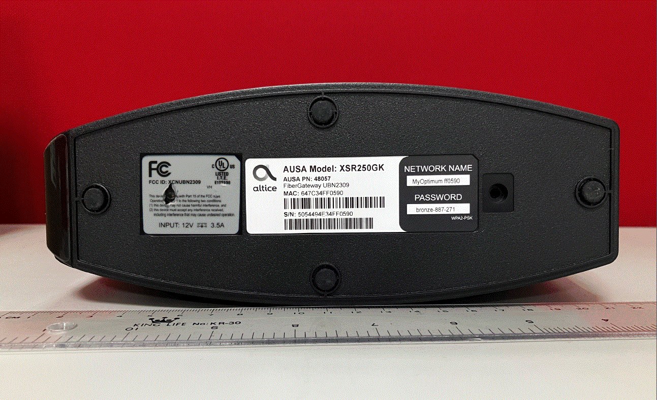
XCNUBN2309
Aug 27, 2023XGS-PON
Equipment Class
DTS - Digital Transmission System
XCNUBN2310
Jul 25, 2023GPON
Equipment Class
NII - Unlicensed National Information Infrastructure TX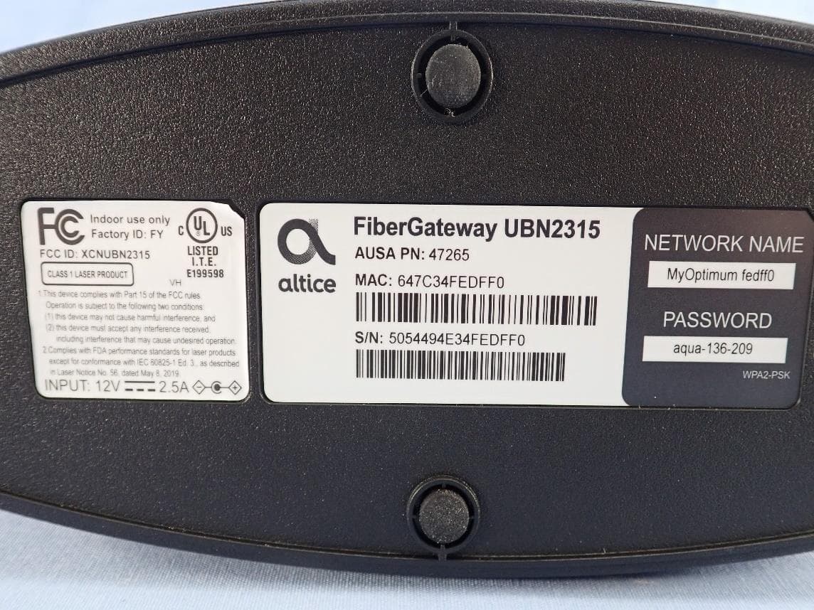
XCNUBN2315
Mar 04, 2023GPON IAD
Equipment Class
6ID - 15E 6 GHz Low Power Indoor Access Point
XCNUBC1340
Feb 01, 2023WeMTA
Equipment Class
6ID - 15E 6 GHz Low Power Indoor Access Point
XCNUBC1330
Jan 28, 2023Docsis3.1 advance WiFi 6E Voice Gateway
Equipment Class
6ID - 15E 6 GHz Low Power Indoor Access Point