XE2TF6UHF RFID Reader
Thinkify LLC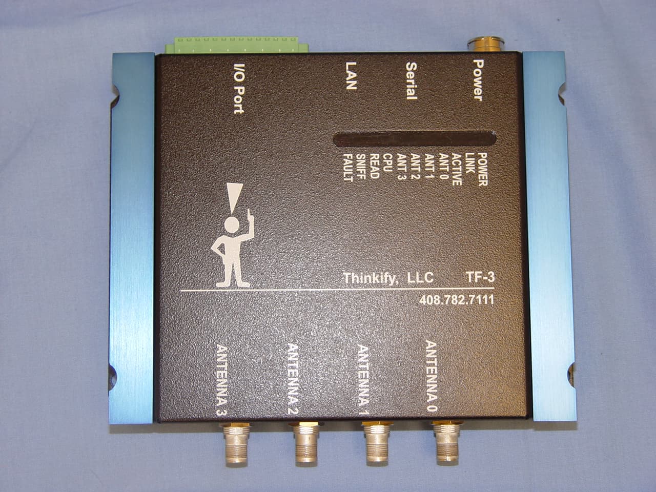
Click to zoom
Application Details
- Equipment Class
- LMS - Part 90 Location & Monitoring Transmitter
- Date of Grant
- Nov 27, 2010
- Application Purpose
- Original Equipment
- Date of Application
- Nov 19, 2010
- Equipment Note
- UHF RFID Reader
- Frequency Range
- 902.75000000 - 927.75000000
- Company
- Thinkify LLC
- Country
- United States
Documents & Files
Document Text
Text extracted from the exhibit documents filed with the FCC. Open a document above to read the original.
Users Manual
User manual – Installation Instructions IDT T1000 TR 1000 Rail Reader Thinkify 18450 Technology Drive Morgan Hill, Ca. 95037 Product name: IDT T1000 Model Number: TR 1000 Legal Notice: Copyright 2009 Thinkify LLC all rights reserved. DOCUMENTATION IS PROVIDED “AS IS” AND ALL EXPRESSED OR IMPLIED CONDITIONS,REPRESENTATIONS AND WARANTEES, INCLUDING ANY IMPLIED WARRANTY, FITNESS FOR A PARTICULAR PURPOSE OR NON- INFRINGMENT ARE HEREBY ISCLAIMED, EXCEPT TO THE EXTENT THAT SUCH DISCLAIMERS ARE HELD TO BE LEGALLY INVALID. Professional Installation: The IDT T1000 is a Part 90 LMS device. It is not available to the general public. This product requires Professional Installation. Only professional installers are allowed to set this unit up for its' intended use. The IDT T1000 is only available to these professional installers. It is the responsibility of these installers to obtain a site license from the FCC for Part 90 operation and install the interrogator in a safe and secure manner consistent with the intent of the regulations. Sole User: IDT is the sole user authorized for use of this device for any and all rail applications. Anyone using this device for rail applications must operate this device under authorization and with agreement from IDT. IDT is trained in the operation of installing part 90 devices and this device in particular. They are professional contractors. IDT has the responsibility of obtaining a site license for use to operate this reader as a part 90 device. FCC Compliance: This equipment complies with Part 90 of the FCC Rules and Regulations. A site license is required for each installation. It is the responsibility of the system integrator/installer or user to obtain the site license. FCC Compliance (Digital Devices): This equipment had been tested and found to comply with the limits of Class A digital device, pursuant to Part 15 of the FCC Rules. These limits are designed to provide reasonable protection against harmful interference when the equipment is operated in a commercial environment. This equipment generates, uses and can radiate radio frequency energy and, if not installed and used in accordance with the instruction manual, may cause harmful interference with radio communications. Operation of this equipment in a residential area is likely to cause harmful interference in which the user will be required to correct the interference at his own expense. Caution: The IDT 1000D radiates energy. The RF emissions must be evaluated in accordance with FCC OET Bulletin 56 “Hazards of radio frequency and electromagnetic fields” and Bulletin 65 “Human exposure to radio frequency electromagnetic fields” and appropriate precautions implemented. All individuals working on or near the antenna should not be closer than 2 feet to the antenna when the RFID reader is operating into a 12 dBi antenna. This is the minimum distance for human exposure recommended by FCC OET Bulletin 56. Installation Instructions: The unit should be removed from the box and mounted on a metal plate for heat dissipation. The power supply should be also mounted on a metal plate for heat dissipation. Coax connectors should be attached and ran to an antenna of 12 dBi gain or less. Connection to the network can take place in a serial or parallel manner. All pertinent I/O can also now be connected. The unit should now be connected to power and power can be monitored using the status lights on the reader. The unit should not be allowed to be at full power and continuously “on” for over 30 minutes at a time. Continuous operation in the “on” condition at full power can decrease the useful life of the unit. The unit has been type accepted at temperatures between -20 and plus 50 degrees C. Operation at temperatures above 35 degrees C without air circulation and a heat sink is not recommended. Model Number ALR-9900 Model Number ALR-9900 Specifications Table Architecture XScale processor, Linux, 64 Mbytes RAM, 64 Mbytes Flash Supported RFID Tag Protocols EPC Gen 2; ISO 18000-6c, North American Rail Reader Protocols Alien Reader Protocol, SNMP, firmware upgradeable LAN Protocols DHCP, TCP/IP, NTP Frequency 902.75 MHz – 927.25 MHz Channels 50 Channel Spacing 500 KHz RF Power Max at output port 32 dBm Power Tri-voltage AC/DC power converter; 45 Watts maximum 120 or 240 VAC Communications RS-232 (DB-9 F), LAN TCPI/IP (RJ-45) I/O 4 inputs, 8 outputs, optically isolated, 0.5 amp, external power source of less than 24 volts Dimensions (L) 8.0” x (W) 8.3” x (D) 1.8” Weight 1.5 kg (4.4 lb) Operating Temperature -20°C to +50°C (-4°F to +122°F) Dust and Moisture IP53 LED Indicators Power, Link, Active, Ant 0-3, CPU, Read, Sniff, Fault RF Connectors reverse T&C Approved power supply: Rong Hong or XP or DSC equivalent Pinouts RS-232 Port Pinouts RS-232 Connector (Female DB-9F) Pin 1 DCD Connected to Pin 6 Pin 2 TR1 Transmit Data (Output) Pin 3 RC1 Receive Data (Input) Pin 4 DTR Connected to Pin 6 Pin 5 Ground Pin 6 DSR Connected to Pin 4 Pin 7 RTS Connected to Pin 8 Pin 8 CTS Connected to Pin 7 Pin 9 Not Connected IO Port Terminal Interface I/O Port Screw Terminal Connector (F Pin 1 V+ Pin 2 Not connected Pin 3 Not connected Pin 4 Not connected Pin 5 Not connected Pin 6 Not connected Pin 7 Not connected Pin 8 Not connected Pin 9 Not connected Pin 10 Input 0 Pin 11 Input 1 Pin 12 Input 2 Pin 13 Input 3 Pin 14 V- Diagnostic LEDs The ALR-9890 - RR includes diagnostic LEDs on the face of the reader to provide easy and convenient external indication for various operating conditions: POWER (green) - indicates power is applied to the reader LINK (green) – indicates that the reader is connected to the network ACTIVE (green) – indicates reader is transmitting on the network ANT 0 – ANT 3 (green) – indicates that the reader is transmitting power on the specified antenna port CPU (green) – indicates that the CPU has booted successfully and is running normally. READ (green) – indicates that the reader is receiving data from a tag SNIFF (green)…
Text truncated - open the document above for the full version.
Cover Letter(s)
Federal Communications Commission Equipment Authorization Branch 7435 Oakland Mills Road Columbia, MD 21046 ratw20r0 Request for Confidentiality Company name: Thinkify FCC lD: XE2TFG FCC Part 90 Certification Gentlemen, In accordance with 0.459 of CFR 47, Thinkify hereby requests confidentiality of all Block Diagrams, Circuit Description, CircuitDiagrams, Parts List, Operational Description and internal photographs attachments for the subject application. These documents contain detailed system and equipment description and related information about the product which Thinkify considers to be proprietaiy, con1dential and a custom design and othenrvise would not release to the general public. Since the design is a basis from which future technological products will evolve. Thinkify considers that this information would be of benefit to its competitors and that the dlsclosure of the information in these documents would give competitors an unfair advantage in the market. Signature Curt Carrender Thinkify 18450 Technology Drive Morgan Hill, Ca. 95037 cell 408-608-8795 office 408-782-7ILL curt@th inkifyit. com
Cover Letter(s)
? 7l CI Letter of Auth orazation Company: Thinkify LLC Address: 18450 Technology Drive suite E, Morgan Hill, 95037 FCC ID: XE2TF6 Model Number: TR 1000, IDT T1000 We auth orize M|COM Labs, 440 Boulder Court, Suite 200, Pleasanton, CA 94566, USA, to act on our behalf on alt matters concerning the above named equipment. This shall include the following: Testing Approval applications and procedures Payment of approval fees We declare that MiCOM Labs, 44A Boulder Court, Suite 200, Pleasanton, CA 94566, USA, is allowed to forward all information related to the approval project to the applied notified body and to the notification entities and to discuss any issues concerning the approval application. Any and all acts carried out by M|COM Labs on our behalf shall have the same effect as acts of our own. Name: Curt Carrender Date: October 12th 2c1A Title: Engineer Signature of applicant
External Photos
MiCOM Labs, 440 Boulder Court, Suite 200, Pleasanton, CA 94566 Tel: +1 (925) 462-0304, Fax: +1 (925) 462-0306, Web: www.micomlabs.com the wireless lab 4 November 2010 External Photographs IDT T1000 & TR 1000 External Top View Page 2 of 3 the wireless lab Page 3 of 3 the wireless lab Label Artwork
ID Label/Location Info
Sheet1 Page 1 Thinkify, LLC Model: IDT T1000, TR 1000 Frequency Range: 902 – 904MHz & 909.75 – 921.75MHz FCC ID: XE2TF6 FCC Part 90 Location and Monitoring Service Non-Multiliteraton. Site license is required for use of this product Phone (408) 782-7111 www.Thinkifyit.com
Internal Photos
the wireless lab 8 October 2010 Internal Photographs TR 1000 Internal View MiCOM Labs, 440 Boulder Court, Suite 200, Pleasanton, CA 94566 Tel: +1 (925) 462-0304, Fax: +1 (925) 462-0306, Web: www.micomlabs.com the wireless lab Main Assy Front Page 2 of 5 the wireless lab Main Assy Back Page 3 of 5 the wireless lab RF Assy Front Page 4 of 5 the wireless lab RF Assy Back Page 5 of 5
RF Exposure Info
the wireless lab Maximum Permissible Exposure FCC, Part 90 Subpart C §90.1217 Maximum Permissible Exposure Limits §90.1217 Systems operating under the provisions of this section shall be operated in a manner that ensures that the public is not exposed to radio frequency levels in excess of the Commission’s guidelines. See §1.1307 (b)(1) of this chapter. Limit = 1mW / cm2 from 1.310 Table 1 Note: for mobile or fixed location transmitters the minimum separation distance is 20cm, even if calculations indicate the MPE distance to be less. Laboratory Measurement Uncertainty for Power Measurements Measurement uncertainty ±1.33dB Calculations for Maximum Permissible Exposure Levels The EUT has a single transmitter. The peak power in the table below is calculated by assuming a worst case scenario for the maximum gain antenna and output power. The calculated separation distance is for worst case highest power level. Power Density = Pd (mW/cm2) = EIRP/(4πd2) EIRP = P * G P = Peak output power (mW) G = Antenna numeric gain (numeric) d = Separation distance (cm) Numeric Gain = 10 ^ (G (dBi)/10) Because the EUT belongs to the General Population/Uncontrolled Exposure the limit of power density is 1.0 mW/cm2 Freq. Band Antenna Gain Peak Output Power Antenna Gain EIRP Distance @ 1mW/cm2 Minimum Separation Distance (MHz) (dBi) (dBm) (numeric) (mW) Limit(cm) (cm) 900 12 30.81 15.848932 19098.53 38.99 38.994664 MiCOM Labs, 440 Boulder Court, Suite 200, Pleasanton, CA 94566 Tel: +1 (925) 462-0304, Fax: +1 (925) 462-0306, Web: www.micomlabs.com
Test Report
Test of Thinkify IDT T1000, TR 1000 To: FCC 47 CFR Part 90 SubPart I, 90.353 Test Report Serial No.: THNK03-U2 Rev A TEST REPORT FROM Test of Thinkify IDT T1000, TR 1000 To FCC 47 CFR Part 90 SubPart I, 90.353 Test Report Serial No.: THNK03-U2 Rev A This report supersedes THNK01-A2 Rev A Manufacturer: Thinkify LLC 18450 Technology Drive, Suite E Morgan Hill, California 95037 USA Product Function: Wireless Broadband Access Point Copy No: pdf Issue Date: 18th October 2010 This Test Report is Issued Under the Authority o f; MiCOM Labs, Inc. 440 Boulder Cour t, Suite 200 Pleasanton, CA 94566 USA Phone: +1 (925) 462-0304 Fax: +1 (92 5) 462-0306 www.micomlabs.com TESTING CERTIFICATE #2381.01 MiCOM Labs is an ISO 17025 Accredited Testing Laboratory Title: Thinkify IDT T1000, TR 1000 To: Serial #: Issue Date: Page: FCC 47 CFR Part 90 SubPart I, 90.353 THNK03-U2 Rev A 18th October 2010 3 of 105 This test report may be reproduced in full only. The document may only be updated by MiCOM Labs p ersonnel. Any changes will be noted in the Document History section of the report. MiCOM Labs Inc, 440 Boulder Court, Suite 200, Pleasanton, CA 94566 USA, Phone: 925.462.0304, Fax: 925.462.0306, www.micomlabs.com This page has been left intentionally blank Title: Thinkify IDT T1000, TR 1000 To: Serial #: Issue Date: Page: FCC 47 CFR Part 90 SubPart I, 90.353 THNK03-U2 Rev A 18th October 2010 4 of 105 This test report may be reproduced in full only. The document may only be updated by MiCOM Labs p ersonnel. Any changes will be noted in the Document History section of the report. MiCOM Labs Inc, 440 Boulder Court, Suite 200, Pleasanton, CA 94566 USA, Phone: 925.462.0304, Fax: 925.462.0306, www.micomlabs.com TABLE OF CONTENTS 1 ACCREDITATION, LISTINGS & RECOGNITION ...................................................5 1.1 TESTING ACCREDITATION ................................................................................. 5 1.2 RECOGNITION ...................................................................................................... 6 1.3 PRODUCT CERTIFICATION ................................................................................. 7 2 DOCUMENT HISTORY .............................................................................................8 3 TEST RESULT CERTIFICATE .................................................................................9 4 REFERENCES AND MEASUREMENT UNCERTAINTY ......................................10 4.1 Normative References .......................................................................................... 10 4.2 Test and Uncertainty Procedures ......................................................................... 11 5 PRODUCT DETAILS AND TEST CONFIGURATIONS ........................................12 5.1 Technical Details .................................................................................................. 12 5.2 Scope of Test Program ......................................................................................... 13 5.3 Equipment Model(s) and Serial Number(s) .......................................................... 16 5.4 Antenna Details .................................................................................................... 16 5.5 Cabling and I/O Ports ........................................................................................... 16 5.6 Test Configurations............................................................................................... 17 5.7 Equipment Modifications....................................................................................... 18 5.8 Deviations from the Test Standard ....................................................................... 18 5.9 Subcontracted Testing or Third Party Data .......................................................... 18 6 TEST SUMMARY ....................................................................................................19 7 TEST RESULTS ......................................................................................................20 7.1 Device Characteristics .......................................................................................... 20 7.1.1 Occupied Bandwidth ............................................................................. 20 7.1.2 Effective Radiated Power ...................................................................... 34 7.1.3 Maximum Permissible Exposure ........................................................... 37 7.1.4 Frequency Stability; Temperature Variations, and Voltage Variations .. 38 7.1.5 Spectrum Mask (Band-Edge) ................................................................ 50 7.1.6 Conducted Spurious Emissions at Antenna Terminals ......................... 56 7.1.7 Radiated Spurious Emissions - Transmitter .......................................... 71 7.1.8 Radiated Spurious Emissions – Digital Apparatus ................................ 85 7.1.9 Conducted Disturbance at Mains Terminal (150 kHz – 30 MHz) .......... 92 8 TEST SET-UP PHOTOGRAPHS............................................................................97 8.1 General Measurement Test Set-Up ...................................................................... 97 8.2 Frequency Error Test Set-Up – Environmental Chamber ..................................... 98 8.3 AC Wireline Emissions ......................................................................................... 99 8.4 Radiated Radio Emissions < 1GHz .................................................................... 100 8.5 Radiated Radio Emissions > 1GHz .................................................................... 101 8.6 Radiated Digital Emissions < 1GHz.................................................................... 102 8.7 Radiated Digital Emissions > 1GHz.................................................................... 103 9 TEST EQUIPMENT DETAILS.......................................................................…
Text truncated - open the document above for the full version.
Test Setup Photos
MiCOM Labs, 440 Boulder Court, Suite 200, Pleasanton, CA 94566 Tel: +1 (925) 462-0304, Fax: +1 (925) 462-0306, Web: www.micomlabs.com the wireless lab 8 October 2010 Test Set Up Photographs TR 1000 General Measurement Test Set-Up Page 2 of 7 the wireless lab Frequency Error Test Set-Up – Environmental Chamber Page 3 of 7 the wireless lab AC Wireline Emissions Page 4 of 7 the wireless lab Radiated Radio Emissions < 1GHz Page 5 of 7 the wireless lab Radiated Radio Emissions > 1GHz Page 6 of 7 the wireless lab Radiated Digital Emissions < 1GHz Page 7 of 7 the wireless lab Radiated Digital Emissions > 1GHz
Contact Information
Applicant
Curt L Carrender
Technical Contact
Test Firm
Micom LabsGordon Hurst
Technical Specifications
| # | Rule Parts | Frequency Range | Power Output | Emission | Tolerance |
|---|---|---|---|---|---|
| 1 | 90.353 | 902.75 MHz - 927.75 MHz | 1.206 W | 63K1L1D | 20.0000000000 ppm |
Other Applications from Thinkify LLC
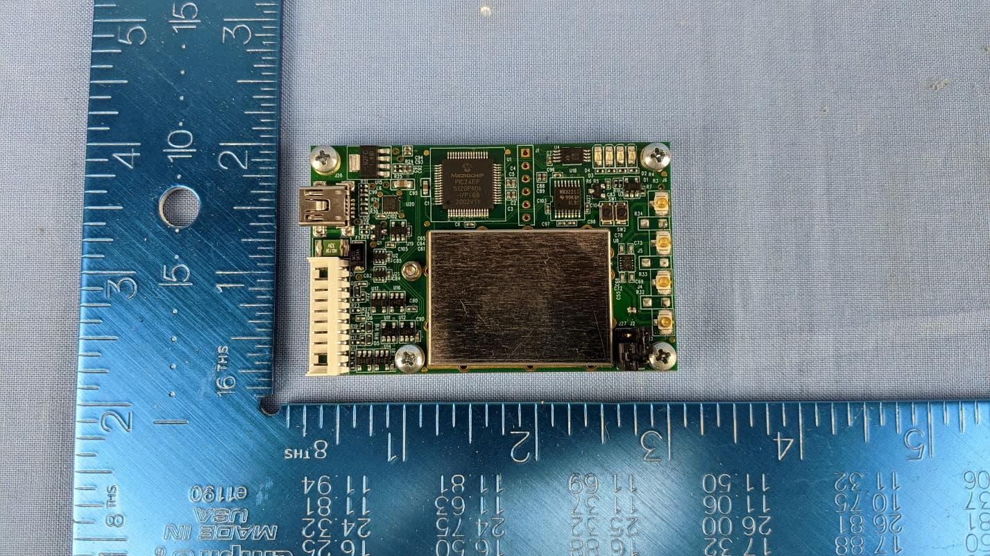
XE2C
Feb 02, 2021UHF RFID Reader Module
Equipment Class
DSS - Part 15 Spread Spectrum TransmitterXE2TF8
Sep 17, 2015T2000 AEI Reader
Equipment Class
LMS - Part 90 Location & Monitoring Transmitter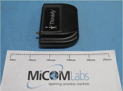
XE2TF7
Sep 30, 2014UHF RFID 915 MHz Module
Equipment Class
DSS - Part 15 Spread Spectrum Transmitter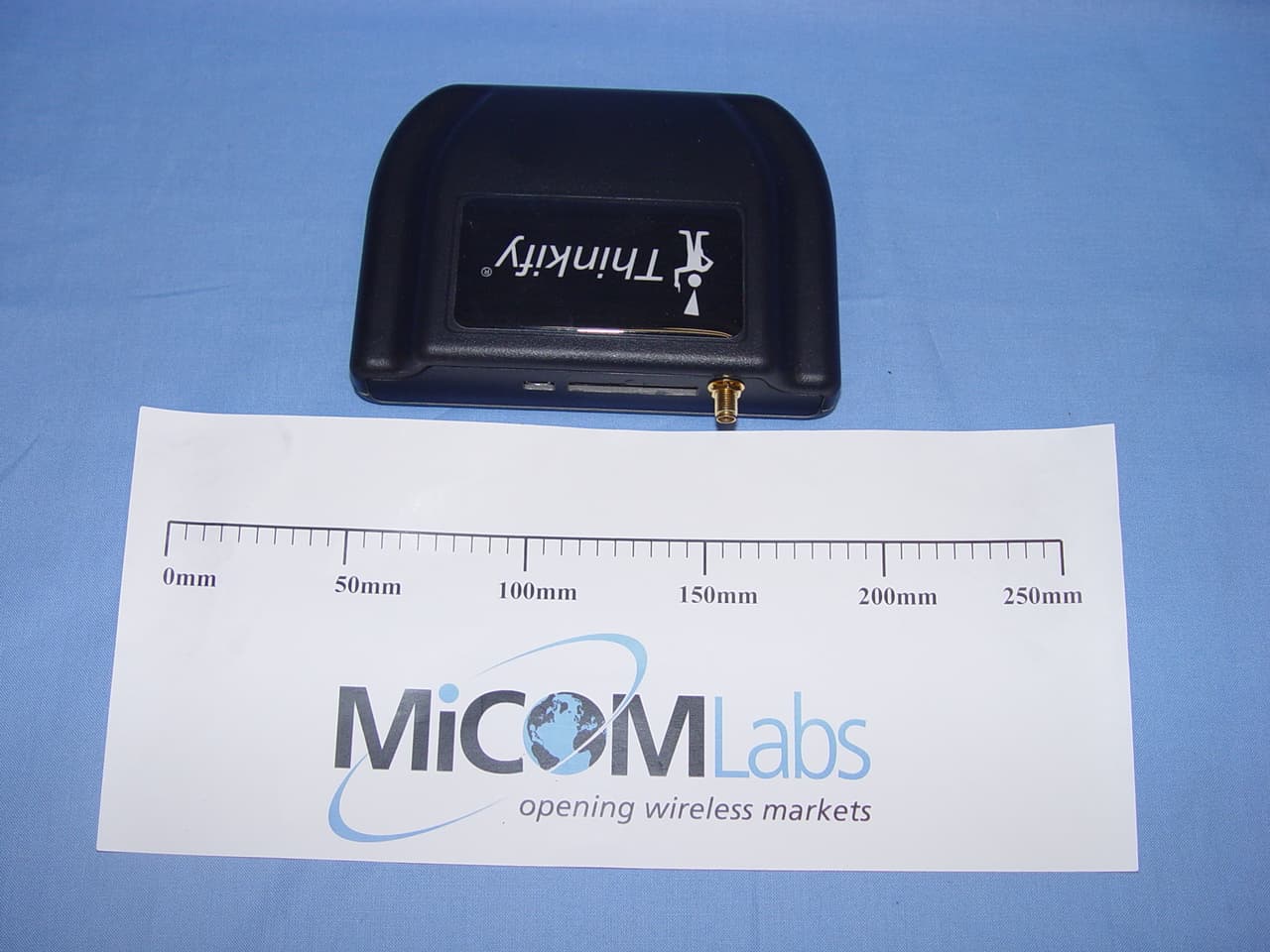
XE2TF4
Nov 18, 2010UHF RFID Reader
Equipment Class
DSS - Part 15 Spread Spectrum Transmitter