XJN-PA0900MID
SHUOYING INDUSTRIAL (SHENZHEN) CO., LTD.
Click to zoom
Application Details
- Equipment Class
- DTS - Digital Transmission System
- Date of Grant
- Apr 27, 2013
- Application Purpose
- Original Equipment
- Date of Application
- Apr 27, 2013
- Equipment Note
- MID
- Frequency Range
- 2422.00000000 - 2452.00000000
- Country
- China
Documents & Files
Document Text
Text extracted from the exhibit documents filed with the FCC. Open a document above to read the original.
Users Manual
0 PA0900 Quick Start Guide 1 Thank you for choosing this disgo product. We are sure you will enjoy using it. The Tablet 9000 is fully equipped to offer you the complete browsing and multimedia experience. Mydisgo Support If you have any queries relating to the product, please do not hesitate to contact us. On our website; View the full user manual or Frequently Asked Questions; www.mydisgo.info/support Email our Technical Support team directly; [email protected] 2 Description of the device Starting up Before using your disgo for the first time, please charge the battery completely. Charging the battery a) Connect the supplied power cable to the Tablet 9000 power connector and the wall outlet. b) Please allow a minimum of 4 hours for a full charge of the battery. 3 disgo tablet 9000 interface The disgo device uses a full capacitive touchscreen. All areas of the touchscreen will react when you tap on it with your finger. 4 Menu bar icons explained Return Returns to the previously viewed screen Home Touch on Home to return to th e desktop. This action will not close the applications that are open. Recent applications Displays list of recently opened applications Menu Provides access to Wallpaper, Applications and Settings options Volume Control Increase / Decrease volume Other Messages Shows information such as memory card connected and Wi-Fi connection Time Indicator Shows current time Battery Indicator Shows the charge status of the battery. Applications Opens Application / Widgets screen The menu bar will change depending on which screen is being displayed. 5 Finding your way around After the start-up procedure is complete, the tablet will show the Home screen, as below. Please note; the wallpaper on your device may differ fr om that shown within the images in this guide. Slide your finger horizontally on the display to move to the extended screens on the left or right. 6 Customising the Home screen To add a Home screen icon (application, shortcut, widget, etc), touch the Application icon, , which is located at the top-right corner of the screen. Hold yo ur finger on the desired app/widget and drag it to the desired location on the Home screen. You can also customise the wallpaper by touching the Menu icon, . Here you can choose from pre- loaded ‘Live’ and standard wallpaper options. The Me nu icon also allows you to manage applications and system settings. To delete an app or widget from the desktop; press, hold and drag the icon to “x Remove” which appears at the top of the page as shown below. 7 The App Drawer 8 The Application drawer can be accesse d by pressing the application icon, on the Home screen. The Application drawer gives access to all pre-load ed and downloaded apps and widgets on the device, including Mail, Music, Video player (Super HD-Player), Clock, Bookmarks, etc. Tap on any application icon to op en the corresponding application. You can get more Android applications via the SlideM e market or the disgo apps bookmark, which can be found on the Home screen. Connecting to the internet 9 The Tablet 9000 connects to the internet over a Wi-Fi network. If you have connected the device to a network previously, it will attempt to reconnect to the network. a) To configure a new Wi-Fi connection, go to the Home screen, tap the Menu icon and then select System Settings. b) In the Settings screen, under the Wireless & Networks option, touch the Wi-Fi On/Off button to turn the Wi-Fi on or off. c) With the Wi-Fi turned on, the screen will then show all available wireless networks. d) Tap to select the wireless network name you want to connect to. Enter the required pass code, if applicable and tap Connect. You are now fully connected to yo ur network and to the internet! 10 Transferring media to your disgo Tablet 9000 The Tablet 9000 allows for file transfer in three different ways: 1. Via the USB OTG port, When connected to a PC using a USB-A to mini USB- B cable (not supplied), the PC will recognise the internal storage of the tablet. It is then poss ible to transfer files to and from the Tablet. 2. Via an external drive, When connected, the tablet will recognise a USB drive (not supplied) which can be attached to the Tablet via the supplied USB adapter cable. It is then possible to transfer files to and from the Tablet. 3. Via the MicroSD card slot, Files can be transferred directly to and from a MicroSD card. a) Remove the MicroSD card with the Tablet 9000 powered off or use dismount procedure, see user manual at www.mydisgo.info/support b) Connect the MicroSD card to your comp uter and copy the relevant files. c) Replace the card back in the Tablets MicroSD card slot. The copied files (images, music, video, etc) will appear in the relevant app, i.e. music files will appear in the music app, video files will appear in the Super-HD player, etc. 11 Recycling This crossed bin symbol on the appliance indicates that the product, at the end of its life, must be disposed of separately from domestic waste, either by taking it to a separate waste disposal site for electric and electronic appliance or by returning it to your dealer when you buy another similar appliance. The user is responsible for taking the a ppliance to a special waste disposal site at the end of its life. If the disused appliance is collected correctly as separate waste, it can be recycled, treated and disposed of ecologically; this avoids a negative impact on both the environment and health, and contributes towards the recyclin g of the product’s materials. Fo r further information regarding the waste disposal service available, contact your local waste disposal agency or the place of purchase. Battery statement CMS Peripherals Limited is registered as a producer under The Waste Batteries and Accumulator Regulations 2009. The battery in this device is not intended to be removed by the individual or end user. At the end of the product life, or the expiry of the product, the relevant local council appointed WEEE …
Text truncated - open the document above for the full version.
Attestation Statements
SHUOYING INDUSTRIAL (SHENZHEN) CO., LTD. Date: 2013-04-23 To: Federal Communications Commission 7435 Oakland Mills Road Columbia, MD FCC ID: XJN-PA0900 To Whom It May Concern: This letter is to ascertain that Shenzhen Yudafu Electronic Co., Ltd. MID MODEL No.: PA0900 has been the units used for conducting FCC compliance testing, the DoC part will be tested by FCC recognized test lab. If you have any question or concerns, pls. contact us. Sincerely, Contact Person: Tony Pan / General Manager E-mail: : [email protected] Phone: 86-755-29809865 Fax: 86-755-28177333 Address : NO.1Shuoying Road, Hebei Industry Area, Dalang, Longhua Town,Baoan, Shenzhen, China
Cover Letter(s)
SCS-F18: Project and Product Certification Representative Authorization Letter Page 1 of 2 Rev 3.0 775 Montague Expressway Milpitas, CA 95035 Tel: 408-526-1188 Fax: 408-526-1088 Email: [email protected] Project and Product Certification Representative Authorization Letter Revision History Reason for Amendment (current / obsolete) From To Approved Date Initial Release (obsolete) 1.0 1.0 Nov-14-2006 Revised wording (obsolete) 1.0 2.0 Sept–25-2007 Updated company template (current) 2.0 3.0 Jan-31-2012 SCS-F18: Project and Product Certification Representative Authorization Letter Page 2 of 2 Rev 3.0 SHUOYING INDUSTRIAL (SHENZHEN) CO., LTD. Date: 2013-04-23 To: SIEMIC, INC. 775 Montague Expressway, Milpitas, CA 95035 USA Dear Sir/Madam, Re: Project and Product Certification Representative Authorization Letter We, SHUOYING INDUSTRIAL (SHENZHEN) CO., LTD. hereby authorize SIEMIC, INC. to act as a Certification Body for certifying for the following project(s): FCC ID: XJN-PA0900 (MID MODEL No.: PA0900) We affirm that between SIEMIC and SHUOYING INDUSTRIAL (SHENZHEN) CO., LTD., any difference in understanding, including test plan, measurement methods, applicable standards and relevant procedures and processes have been resolved prior to commencement of testing activities. Sincerely, Contact Person: Tony Pan / General Manager E-mail: : [email protected] Phone: 86-755-29809865 Fax: 86-755-28177333 Address : No.1 Shuoying Road, Hebei Industry Area, Dalang, Longhua Town,Baoan, Shenzhen, China
Cover Letter(s)
SCS-F19: Confidentiality Request Letter Page 1 of 2 Rev 3.0 775 Montague Expressway Milpitas, CA 95035 Tel: 408-526-1188 Fax: 408-526-1088 Email: [email protected] Confidentiality Request Letter Revision History Reason for Amendment (current / obsolete) From To Approved Date Initial Release (obsolete) 1.0 1.0 Nov-14-2006 Adding CFR 2.459 (obsolete) 1.0 2.0 August – 11 - 2008 Updated company template & Added text box (current) 2.0 3.0 Jan-31-2012 SCS-F19: Confidentiality Request Letter Page 2 of 2 Rev 3.0 SHUOYING INDUSTRIAL (SHENZHEN) CO., LTD. Date: 2013-04-23 To: Federal Communications Commission Authorization and Evaluation Division 7435 Oakland Mills Road Columbia, MD Subject: Permanent Confidentiality Request for FCC ID: XJN-PA0900 We hereby request confidential treatment of information accompanying this application as outlined below: - Block Diagram - Schematics - Operational Description The above materials contain trade secrets and proprietary information not customarily released to the public. The public disclosure of these materials may be harmful to the applicant and provide unjustified benefits to its competitors. The applicant understands that pursuant to Section 0.457 & 0.459 of the Rules, disclosure of this application and all accompanying documentation will not be made before the date of the Grant for this application. Sincerely, Contact Person: Tony Pan / General Manager E-mail: : [email protected] Phone: 86-755-29809865 Fax: 86-755-28177333 Address : No.1 Shuoying Road, Hebei Industry Area, Dalang, Longhua Town,Baoan, Shenzhen, China
ID Label/Location Info
Label loacation
ID Label/Location Info
ID Label MID FCC ID: XJN-PA0900 Model Number: PA0900 Made in China This device complies with Part 15 of the FCC Rules. Operation is subject to the following two conditions: (1) this device may not cause harmful interference, and (2) this device must accept any interference received, including interference that may cause undesired operation.
Internal Photos
Antenna Wifi Module
RF Exposure Info
FCC ID: XJN-PA0900 WLAN (Portable device) According to §15.247(e)(i) and §1.1307(b)(1), systems operating under the provisions of this section shall be operated in a manner that ensures that the public is not exposed to radio frequency energy level in excess of the Commission’s guidelines. According to KDB447498 D01 General RF Exposure Guidance V05 Frequency Range Low Frequency (MHz) High Frequency(MHz) Center frequency (MHz) Limitation (mw) 2412 2462 2437 10.mw Maximum measured transmitter power: 802.11b Conducted Power (dBm) Conducted Power (mw) Max Antenna Gain (dBi) EIRP (mw) 7.90 6.16 2 9.77 Maximum measured transmitter power: 802.11g Conducted Power (dBm) Conducted Power (mw) Max Antenna Gain (dBi) EIRP (mw) 7.55 5.69 2 9.44 Maximum measured transmitter power: 802.11nHT20 Conducted Power (dBm) Conducted Power (mw) Max Antenna Gain (dBi) EIRP (mw) 7.12 5.15 2 8.17 Maximum measured transmitter power: 802.11nHT40 Conducted Power (dBm) Conducted Power (mw) Max Antenna Gain (dBi) EIRP (mw) 6.50 4.47 2 7.08 For the Tune Up information from the applicant, the maximum output power is 1.51mW, so the worst case of Conducted Power and EIRP will be still less than FCC SAR exemption threshold. Threshold at which no SAR required is 10mw. Maximum Tx power is 9.77mw EIRP Conclusion: No SAR is required. Sincerely, Contact Person: Tony Pan / General Manager E-mail: : [email protected] Phone: 86-755-29809865 Fax: 86-755-28177333 Address : No.1 Shuoying Road, Hebei Industry Area, Dalang, Longhua Town,Baoan, Shenzhen, China
Test Report
TRF NoFCC 15.247/A Page 1 of 76 Report No ES130401010E ELECTROMAGNETIC EMISSIONS COMPLIANCE REPORT INTENTIONAL RADIATOR CERTIFICATION TO FCC PART 15 SUBPART C REQUIREMENT OF MID MODEL No.: PA0900 FCC ID: XJN-PA0900 REPORT NO: ES130401010E ISSUE DATE: April 23, 2013 Prepared for SHUOYING INDUSTRIAL (SHENZHEN) CO., LTD. No.1 Shuoying Road, Hebei Industry Area, Dalang, Longhua Town,Baoan, Shenzhen, China Prepared by SHENZHEN EMTEK CO., LTD. Bldg 69, Majialong Industry Zone, Nanshan District, Shenzhen, Guangdong, China TEL: 86-755-26954280 FAX: 86-755-26954282 This report shall not be reproduced, except in full, without the written approval of SHENZHEN EMTEK CO., LTD. TRF NoFCC 15.247/A Page 2 of 76 Report No ES130401010E VERIFICATION OF COMPLIANCE Applicant: SHUOYING INDUSTRIAL (SHENZHEN) CO., LTD. No.1 Shuoying Road, Hebei Industry Area, Dalang, Longhua Town,Baoan, Shenzhen, China Manufacturer: SHUOYING INDUSTRIAL (SHENZHEN) CO., LTD. No.1 Shuoying Road, Hebei Industry Area, Dalang, Longhua Town,Baoan, Shenzhen, China Product Description: MID Model Number: PA0900 File Number: ES130401010E Date of Test: April 3, 2013 to April 23, 2013 We hereby certify that: The above equipment was tested by SHENZHEN EMTEK CO., LTD. The test data, data evaluation, test procedures, and equipment configurations shown in this report were made in accordance with the procedures given in ANSI C63.4 (2009) and the energy emitted by the sample EUT tested as described in this report is in compliance with conducted and radiated emission limits of FCC Rules Part 15.247. The test results of this report relate only to the tested sample identified in this report. Date of Test : April 3, 2013 to April 23, 2013 Prepared by : Joe Xia/Editor Reviewer : King Wang/Supervisor Approve & Authorized Signer : Lisa Wang/Manager TRF NoFCC 15.247/A Page 3 of 76 Report No ES130401010E Ta b l e o f C o n t e n t s 1. GENERAL INFORMATION ................................................................................................................................ 5 1.1 PRODUCT DESCRIPTION.................................................................................................................................... 5 1.2 RELATED SUBMITTAL(S) / GRANT(S)................................................................................................................. 5 1.3 TEST METHODOLOGY....................................................................................................................................... 6 1.4 SPECIAL ACCESSORIES...................................................................................................................................... 6 1.5 EQUIPMENT MODIFICATIONS............................................................................................................................ 6 1.6 TEST FACILITY.................................................................................................................................................. 6 2. SYSTEM TEST CONFIGURATION ................................................................................................................... 7 2.1 EUT CONFIGURATION....................................................................................................................................... 7 2.2 EUT EXERCISE................................................................................................................................................. 7 2.3 TEST PROCEDURE............................................................................................................................................. 7 2.4 CONFIGURATION OF TESTED SYSTEM............................................................................................................... 7 3. DESCRIPTION OF TEST MODES ..................................................................................................................... 9 4. SUMMARY OF TEST RESULTS....................................................................................................................... 10 5. CONDUCTED EMISSIONS TEST.................................................................................................................... 11 5.1 MEASUREMENT PROCEDURE.......................................................................................................................... 11 5.2 TEST SET-UP (BLOCK DIAGRAM OF CONFIGURATION) .................................................................................. 11 5.3 MEASUREMENT EQUIPMENT USED................................................................................................................. 11 5.4 CONDUCTED EMISSION LIMIT......................................................................................................................... 11 5.5 MEASUREMENT RESULT.................................................................................................................................. 12 6. RADIATED EMISSION TEST ........................................................................................................................... 13 6.1 MEASUREMENT PROCEDURE.......................................................................................................................... 13 6.2 TEST SET-UP (BLOCK DIAGRAM OF CONFIGURATION) .................................................................................. 13 6.3 MEASUREMENT EQUIPMENT USED................................................................................................................. 14 6.4 RADIATED EMISSION LIMIT............................................................................................................................. 14 6.5 MEASUREMENT RESULT.................................................................................................................................. 16 7. 6DB BANDWIDTH TEST...................................................................................................................…
Text truncated - open the document above for the full version.
Test Setup Photos
Radiated test setup: Conducted test setup:
Contact Information
Applicant
Tony Pan
Test Firm
EMTEK (Shenzhen) Co., Ltd.David Lee
Technical Specifications
| # | Rule Parts | Frequency Range | Power Output |
|---|---|---|---|
| 2 | 15C | 2.42 GHz - 2.45 GHz | 4.47 mW |
Other Applications from SHUOYING INDUSTRIAL (SHENZHEN) CO., LTD.
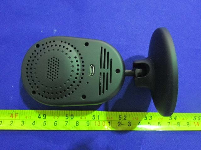
XJN-IPC019
Sep 07, 2015IP Camera
Equipment Class
DTS - Digital Transmission System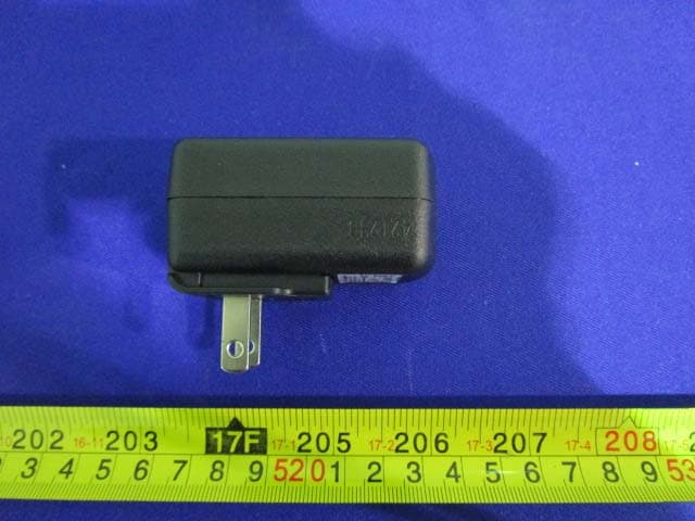
XJN-PA7062X
Dec 27, 2014Mobile Internet Devices
Equipment Class
JBP - Part 15 Class B Computing Device PeripheralXJN-PX4032
Sep 20, 2014Mobile internet device
Equipment Class
DTS - Digital Transmission System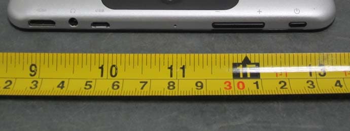
XJN-PA7810X
Jun 26, 2014Mobile Internet Devices
Equipment Class
DSS - Part 15 Spread Spectrum Transmitter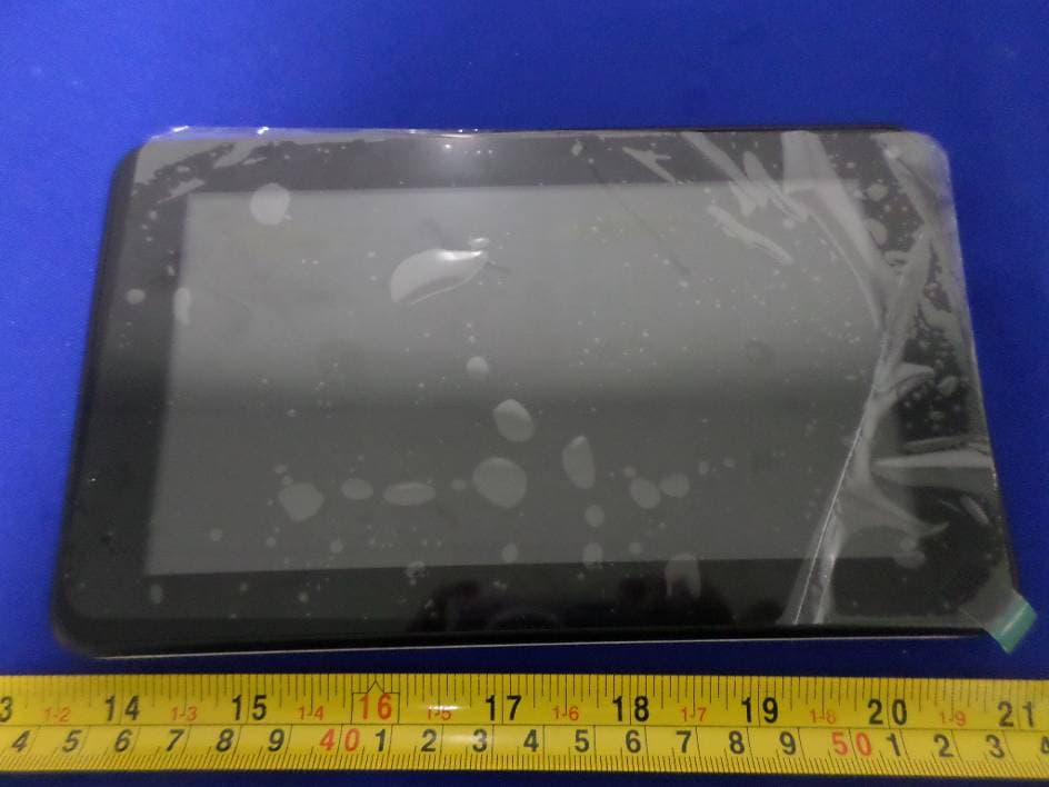
XJN-PR7062X
May 06, 2014Mobile Internet Device
Equipment Class
DTS - Digital Transmission System