XJNDC100Digital Camera
SHUOYING INDUSTRIAL (SHENZHEN) CO., LTD.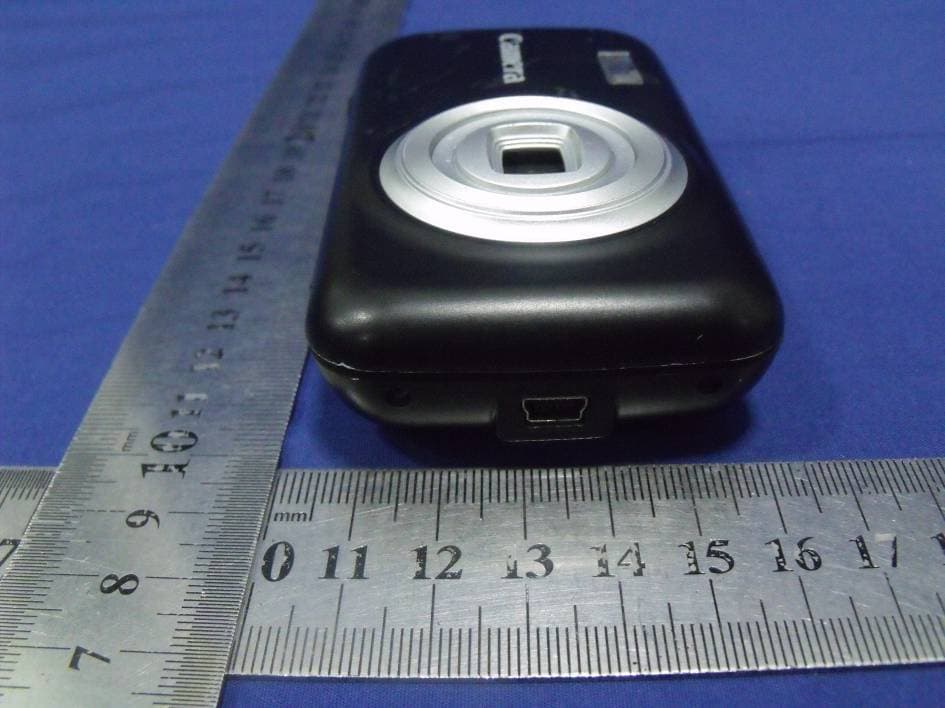
Click to zoom
Application Details
- Equipment Class
- JBP - Part 15 Class B Computing Device Peripheral
- Date of Grant
- Aug 14, 2012
- Application Purpose
- Original Equipment
- Date of Application
- Aug 14, 2012
- Equipment Note
- Digital Camera
- Country
- China
Documents & Files
Document Text
Text extracted from the exhibit documents filed with the FCC. Open a document above to read the original.
Users Manual
1 Foreword Thank you for purchasing this digital video camera. Before use of this video camera, please read this user’s manual carefully and place it in a safe place for future reference. The contents covered in this user’s manual are based on the latest information obtained when this manual was prepared. The screen display pictures, and illustrations, etc., used in this manual are to describe the operations of the video camera in a more detailed and direct viewing manner, but they may be slightly different from the digital video camera you actually use due to the differences in technical developments and production batch. Note Please use this video camera according to the following sequence. Notice for Use This video camera can use TF cards (multimedia memory cards). Instructions for use of memory card ● If a newly purchased memory card is used for the first time, or a memory card contains data or other recorded video camera images, which the video camera cannot recognize, please be sure to format the memory card first. ● Before inserting or removing a memory card, please turn off the power of the video camera first. ● After a memory card is used many times, its performance will be degraded. If the memory card’s performance is degraded, a new memory card should be purchased. Attention: If a newly purchased memory card or a memory card having been used in another digital camera/video camera is to be used in this video camera, please format it using this video camera first. Before formatting, please back up the important data onto other media first, e.g., soft disk, hard disk, CD, etc. Inspect power supply of video camera Insert and format memory card Record video/ take photo Install driver Connect computer 2 ● Memory cards are precision electronic devices. Do not bend any memory card, and avoid dropping it or subjecting it to stress. ● Do not place any memory card into a strong electric field or magnetic field environment, e.g., near a speaker or TV receiver. ● Do not use or place any memory card in too hot or too cold an environment. ● Please keep any memory card clean and avoid it contacting any liquid. If the memory card contacts liquid, wipe it dry with a piece of soft cloth. ● When a memory card is not in use, put it into a card case. ● Note that a memory card will become hot after being used for a long time. This is fully normal. ● Do not use a memory card that has been used in another digital video camera or digital camera. If you want to use it in this digital video camera, format it using this video camera first. ● Do not use a memory card that is formatted in another digital video camera or memory card reader. ● If one of the following occurs for a memory card, the recorded data may be destroyed: - Use the memory card improperly. - Turn off the power or remove the memory card during recording, deleting (formatting), or reading. ● It is recommended that important data be backed up onto other media, such as a soft disk, hard disk, CD, etc. Maintenance and care of video camera When the video camera is not in use, store it in a dry and dark place with the batteries removed. ● Use a proper protective case to avoid scratching the lens and screen. ● To clean the lens surface, blow off the sand and dust on the surface first, and then use a piece of cloth or paper towel suitable for cleaning optical devices to lightly wipe the lens. If necessary, employ lens cleanser. Do not use organic solvent to clean the video camera. ● Do not touch the lens surface by your fingers. System Requirements When operating or using this digital video camera, please refer to the minimum system requirements for a computer that uses the video camera. However, we strongly recommend that you use a better computer device to operate the video camera so as to offer the best efficiency. The minimum system requirements are as follows: System requirements Operating system Microsoft Windows 2000,XP,VISTA,Windows7 CPU Intel PIII667 or above, or equivalent Internal memory 128 MB or more Sound card, display card Sound card, display card, supporting DirectX8, or higher version CD drive 4× or more Hard disk 1 GB or more free space Other One standard USB 1.1 or USB 2.0 interface 3 Functions and Features This video camera has many features and functions: z Digital video camera z Digital camera (130 million pixels) z Mobile disk z Pickup head z 4× digital zoom Accessories When unpacking the video camera, you will see the following main accessories. USB connecting cable User’s manual Brief Introduction to Outside Screen Microphone Shutter key Power key USB interface Operation indicator lamp T key W key Mode key Delete key TF card slot Tripod installation hole 4 Key Functions and Indicator Lamps of Video Camera Key Photographing /Video-recording mode Playback mode Menu setup mode Power key Long press to start up/shut down Short press to enter menu Long press to start up/shut down Short press to enter menu Long press to start up/shut down Short press to close menu Shutter key Take a photo Start/pause video recording Start/stop playing Switch over to setup menu; confirm menu T key Digital zoom in Select file rightwards Switch over to the previous menu W key Digital zoom out Select file leftwards Return to the next menu Mode key Switch over between video-recording mode and playback mode Enter photographing mode N/A Delete key Turn on/ Turn off fill light Delete a photo or video rapidly N/A Fill light Battery compartment cover Lens 5 Start Use Install batteries This video camera uses 3 AAA alkaline batteries. For replacement of batteries, turn off the power of the video camera first. Open the battery compartment cover, install batteries according to the prompt marks for positive and negative polarities on the sides of the battery compartment, and then close the battery compartment cover. Install TF memory card Insert a TF memory card into the memory card slot with the metal pins facing inwards according to the prompt marks on the s…
Text truncated - open the document above for the full version.
Cover Letter(s)
SCS-F18: Project and Product Certification Representative Authorization Letter Page 1 of 2 Rev 3.0 775 Montague Expressway Milpitas, CA 95035 Tel: 408-526-1188 Fax: 408-526-1088 Email: [email protected] Project and Product Certification Representative Authorization Letter Revision History Reason for Amendment (current / obsolete) From To Approved Date Initial Release (obsolete) 1.0 1.0 Nov-14-2006 Revised wording (obsolete) 1.0 2.0 Sept–25-2007 Updated company template (current) 2.0 3.0 Jan-31-2012 SCS-F18: Project and Product Certification Representative Authorization Letter Page 2 of 2 Rev 3.0 SHUOYING INDUSTRIAL (SHENZHEN) CO., LTD. 2012-08-08 To: SIEMIC, INC. 775 Montague Expressway, Milpitas, CA 95035 USA Dear Sir/Madam, Re: Project and Product Certification Representative Authorization Letter We, SHUOYING INDUSTRIAL (SHENZHEN) CO., LTD., hereby authorize SIEMIC, INC. to act as a Certification Body for certifying for the following project(s): FCC ID: XJNDC100 (Digital Camera, DC100) We affirm that between SIEMIC and SHUOYING INDUSTRIAL (SHENZHEN) CO., LTD., any difference in understanding, including test plan, measurement methods, applicable standards and relevant procedures and processes have been resolved prior to commencement of testing activities. Sincerely, Signature Tony Pan / General Manager E-mail: : [email protected] Phone: 86-755-29809865 Fax: 86-755-28177333 Address : NO.1 Shuoying Rd., Hebei Industry Area, Dalang, Longhua Town, Baoan, Shenzhen, China
Cover Letter(s)
Confidentiality Request Letter Revision History Reason for Amendment (current / obsolete) From To Approved Date Initial Release (obsolete) 1.0 1.0 Nov-14-2006 Adding CFR 2.459 (obsolete) 1.0 2.0 August – 11 - 2008 Updated company template & Added text box (current) 2.0 3.0 Jan-31-2012 SHUOYING INDUSTRIAL (SHENZHEN) CO., LTD. (2012-08-07) To: Federal Communications Commission Office of Engineering and Technology Equipment Authorization Division 7345 Oakland Mills Road Columbia, Maryland 21046 Subject: Permanent Confidentiality Request for FCC ID: XJNDC100 We hereby request confidential treatment of information accompanying this application as outlined below: - Block diagram - Operation description - Schematic The above materials contain trade secrets and proprietary information not customarily released to the public. The public disclosure of these materials may be harmful to the applicant and provide unjustified benefits to its competitors. The applicant understands that pursuant to Section 0.457 & 0.459 of the Rules, disclosure of this application and all accompanying documentation will not be made before the date of the Grant for this application. Sincerely, Signature Tony Pan / General Manager E-mail: : [email protected] Phone: 86-755-29809865 Fax: 86-755-28177333 Address : NO.1 Shuoying Rd., Hebei Industry Area, Dalang, Longhua Town, Baoan, Shenzhen, China
ID Label/Location Info
FCC ID: XJNDC100 This device complies with Part 15 of the FCC Rules. Operation is subject to the following two conditions : (1) this device may not cause harmful interference, and (2) this device must accept any interference received, including interference that may cause undesired operation.
ID Label/Location Info
Label Location Proposed Label Location on EUT
Test Report
TRF No. FCC Part 15B/A Page 1 of 28 Report No.: ES120718160E Rev.1.0 FCC Test Report On Behalf of SHUOYING INDUSTRIAL (SHENZHEN) CO., LTD. Digital Camera Model No.: DC100 FCC ID: XJNDC100 Report Number : ES120718160E Date of Test : July 18, 2012 to July 30, 2012 Date of Report : July 31, 2012 Prepared for : SHUOYING INDUSTRIAL (SHENZHEN) CO., LTD. Address : NO.1 Shuoying Rd., Hebei Industry Area, Dalang,Longhua Town, Baoan, Shenzhen, China Prepared by : SHENZHEN EMTEK CO., LTD. Address : Bldg 69, Majialong Industry Zone, Nanshan District, Shenzhen, Guangdong, China Tel: (0755) 26954280 Fax: (0755) 26954282 TRF No. FCC Part 15B/A Page 2 of 28 Report No.: ES120718160E Rev.1.0 TABLE OF CONTENT Test Report Description Page 1. SUMMARY OF TEST RESULT..................................................................................................... 5 2. GENERAL INFORMATION............................................................................................................ 6 2.1. DESCRIPTION OF DEVICE (EUT)...............................................................................................................................6 2.2. DESCRIPTION OF SUPPORT DEVICE..........................................................................................................................6 2.3. DESCRIPTION OF TEST FACILITY...............................................................................................................................7 2.4. MEASUREMENT UNCERTAINTY..................................................................................................................................7 3. MEASURING DEVICE AND TEST EQUIPMENT...................................................................... 8 3.1. FOR POWER LINE CONDUCTED EMISSION MEASUREMENT......................................................................................8 3.2. FOR RADIATED EMISSION MEASUREMENT................................................................................................................8 4. POWER LINE CONDUCTED EMISSION MEASUREMENT................................................... 9 4.1. BLOCK DIAGRAM OF TEST SETUP.............................................................................................................................9 4.2. MEASURING STANDARD.............................................................................................................................................9 4.3. POWER LINE CONDUCTED EMISSION LIMITS (CLASS B)..........................................................................................9 4.4. EUT CONFIGURATION ON MEASUREMENT................................................................................................................9 4.5. OPERATING CONDITION OF EUT...............................................................................................................................9 4.6. TEST PROCEDURE...................................................................................................................................................10 4.7. MEASURING RESULTS..............................................................................................................................................10 5. RADIATED EMISSION MEASUREMENT................................................................................. 13 5.1. BLOCK DIAGRAM OF TEST SETUP...........................................................................................................................13 5.2. MEASURING STANDARD...........................................................................................................................................13 5.3. RADIATED EMISSION LIMITS (CLASS B)..................................................................................................................14 5.4. EUT CONFIGURATION ON MEASUREMENT..............................................................................................................14 5.5. OPERATING CONDITION OF EUT.............................................................................................................................14 5.6. TEST PROCEDURE...................................................................................................................................................14 5.7. MEASURING RESULTS..............................................................................................................................................15 6. PHOTOGRAPHS........................................................................................................................... 24 6.1. PHOTOS OF CONDUCTED EMISSION MEASUREMENT.............................................................................................24 6.2. PHOTOS OF RADIATION EMISSION MEASUREMENT.................................................................................................25 APPENDIX (Photos of EUT) (4 Pages) TRF No. FCC Part 15B/A Page 4 of 28 Report No.: ES120718160E Rev.1.0 Modified History Rev. Summary Date of Rev. Report No. V1.0 Original Report 2012-07-31 ES120718160E TRF No. FCC Part 15B/A Page 5 of 28 Report No.: ES120718160E Rev.1.0 1. SUMMARY OF TEST RESULT EMISSION Description of Test Item Standard & Limits Results Conducted Disturbance at Mains Terminals FCC Part 15, Subpart B, Class B ANSI C63.4: 2009 Pass Radiated Disturbance FCC Part 15, Subpart B, Class B ANSI C63.4: 2009 Pass Note: N/A is an abbreviation for Not Applicable. TRF No. FCC Part 15B/A Page 6 of 28 Report No.: ES120718160E Rev.1.0 2. GENERAL INFORMATION 2.1. Description of Device (EUT) EUT : Digital Camera Model Number : DC100 Test Voltage : DC 4.5V (AAA Battery×3) or DC 5V from PC connected to AC 120V/60Hz Applicant : SHUOYING INDUSTRIAL (SHENZHEN) CO., LTD. Address : NO.1 Shuoying Rd., Hebei Industry Area, Dalang, Longhua Town, Baoan, Shenzhen, Guangdong, China Manufacturer : SHUOYING INDUSTRIAL (SHENZHEN) CO., LTD. Address : NO.1 Shuoying Rd., Hebei Industry A…
Text truncated - open the document above for the full version.
Test Setup Photos
Photos of Conducted Emission Photos of Radiation Emission Measurement
Contact Information
Applicant
Tony Pan
Test Firm
EMTEK (Shenzhen) Co., Ltd.David Lee
Technical Specifications
| # | Rule Parts | Frequency Range | Power Output |
|---|---|---|---|
| 1 | 15B | - | - |
Other Applications from SHUOYING INDUSTRIAL (SHENZHEN) CO., LTD.
XJN-IPC019
Sep 07, 2015IP Camera
Equipment Class
DTS - Digital Transmission System
XJN-PA7062X
Dec 27, 2014Mobile Internet Devices
Equipment Class
JBP - Part 15 Class B Computing Device PeripheralXJN-PX4032
Sep 20, 2014Mobile internet device
Equipment Class
DTS - Digital Transmission System
XJN-PA7810X
Jun 26, 2014Mobile Internet Devices
Equipment Class
DSS - Part 15 Spread Spectrum Transmitter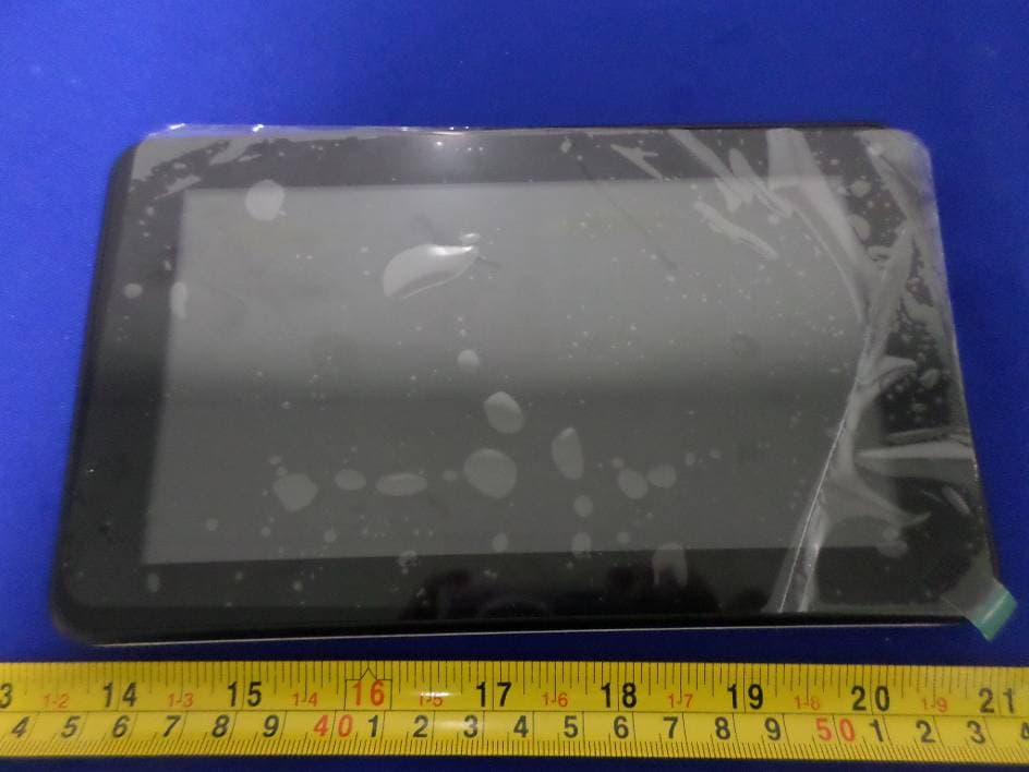
XJN-PR7062X
May 06, 2014Mobile Internet Device
Equipment Class
DTS - Digital Transmission System