XK5-BMPSRBMPSR Module
.steute Schaltgeraete GmbH & Co.KG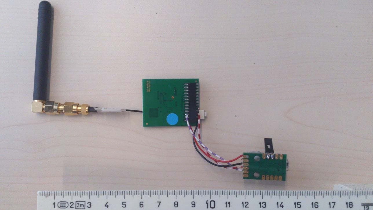
Click to zoom
Application Details
- Equipment Class
- DSS - Part 15 Spread Spectrum Transmitter
- Date of Grant
- Jul 06, 2015
- Application Purpose
- Original Equipment
- Date of Application
- Jul 06, 2015
- Equipment Note
- BMPSR Module
- Frequency Range
- 2402.00000000 - 2480.00000000
- Country
- Germany
Documents & Files
Document Text
Text extracted from the exhibit documents filed with the FCC. Open a document above to read the original.
Users Manual
steute Schaltgeräte GmbH & Co. KGBrückenstraße 91, 32584 Löhne, Germany, www.steute.com // BMPSR Instruction for use Instructions d'utilisation English Table of contents Model and type designation ............................................... 1 Table of contents ..................................................................... 1 General information .............................................................. 1 Regulatory and Safety Compliance European Union ....................... 1 FCC Regulatory Information .............................................. 1 Other regulatory notes for OEM ...................................... 2 A separate approval ............................................................... 2 Standards .................................................................................... 2 Instructions for use BMPSR This manual explains how to integrate the module BMPSR into the end product. It includes procedures that shall assist you to avoid unfore- seen problems.This manual presents information that shows how module or OEM product (with integrated module) complies with regu- lations in certain regions. Model and type designation BMPSR: BlueMod+SR/AP radio module General information This module has to be installed and used in accordance with the tech- nical description/installation instructions provided by the manufactur- er. For detail information concerning type approval of this module (e.g. where this module is already pre-approved) please contact the author- ized local distributor or the manufacturer. The system may only be im- plemented in the configuration that was authorized. Note that any changes or modifications to this equipment not expressly approved by the manufacturer could void the user`s authority to operate this equipment. Regulatory and Safety Compliance European Union Declaration about performed tests The steute module BMPSR is a wireless data transmission system. This RF module can be integrated into various end products. steute declares that the module complies with the following directive and standards: Satisfy all the technical regulations applicable to the product within the scope of council directives LVD 2006/95/EC, EMC 2004/108/EC, R&TTE 1999/5/EC and RoHS 2011/65/EC if used for its intended pur- pose and that the following norms, standards or documents have been applied: - EN 301 489-1 V1.9.2: 2011 - EN 301 489-17 V2.2.1: 2012 - EN 300 328 V1.8.1: 2012 - EN 60 950-1:2006 + A11:2009 + A1:2010 + AC:2011 The technical documentation as required by the Conformity Assess- ment procedure is kept at the following address: steute Schaltgeräte GmbH & Co.KG Brückenstraße 91 32584 Löhne, Germany Telephone ++49 (0) 57 31 / 7 45 – 0 Telefax ++49 (0) 57 31 / 7 45 – 200 eMail: [email protected] www.steute.com Labelling CE conformity marking for product. OEM product/application, where this radio module is integrated/in- stalled in, has to be labelled in accordance to Article 12 of the R&TTE directive. A label has to be permanently affixed to the OEM product/ap- plication. Otherwise OEM product must be approved separately. Regulatory information on the OEM devise should contain labelling like: Approved in accordance to R&TTE directive transmitter module marked by CE, manufactured by steute incorporated to OEM product. More detailed information in chapter “A separate approval”. FCC Regulatory Information The Federal Communication Commission Radio Frequency Interfer- ence Statement includes the following paragraph.This equipment has been tested and found to comply with the limits pursuant to Part 15 of the FCC Rules.These limits are designed to provide reasonable protec- tion against harmful interference in a residential installation. This equipment generates, uses and radiates radio frequency energy and, if not installed and used in accordance with the instructions, may cause harmful interference to radio communication. However, there is no guarantee that interference will not occur in a particular installation. If this equipment does cause harmful interference to radio or television reception, which can be determined by turning the equipment off and on, the user is encouraged to try to correct the interference by one or more of the following measures: - Reorient or relocate the receiving antenna. - Increase the separation between the equipment and receiver. - Connect the equipment into an outlet on a circuit different from that to which the receiver is connected. - Consult the dealer or an experienced radio / TV technician for help. Radiofrequency radiation exposure Information: This equipment complies with FCC radiation exposure limits set forth for an uncontrolled environment. This equipment should be installed and operated with minimum distance of 20cm between the radiator and your body. This transmitter must not be co-located or operating in steute Schaltgeräte GmbH & Co. KGBrückenstraße 91, 32584 Löhne, Germany, www.steute.com // BMPSR Instruction for use Instructions d'utilisation conjunction with any other antenna or transmitter. Not Authorized modification could void authority to use this equipment. Labelling: steute module BMPSR label: FCC Regulatory information. OEM device should contain labelling that: Approved in accordance to FCC rules; transmitter module marked by FCC-ID “XK5-BMPSR” label; manufactured by steute incorporated to OEM product. When it is not possible, user manual should include such information. For example: "This device complies with Part 15 of the FCC Rules and with RSS-210 of Industry Canada. Operation is subject to the following two condi - tions: (1) this device may not cause harmful interference, (2) this de- vice must accept any interference received, including interference that may cause undesired operation." This device contains: FCC-ID XK5- BMPSR. This label will be placed on the final product, clearly visible to all per- sons exposed to the transmitter. The specific location on the final product will be consistent…
Text truncated - open the document above for the full version.
External Photos
Test report no.: 1-9460/15-01-01_AnnexA Page 1 of 3 Annex A This test report annex is electronically signed and valid without handwriting signature. For verification of the electronic signatures, the public keys can be requested at the testing laboratory. Test report annex authorised: David Lang Radio Communications & EMC Test report no.: 1-9460/15-01-01_AnnexA Page 2 of 3 External photos of the EUT Photo 1: Photo 2: Test report no.: 1-9460/15-01-01_AnnexA Page 3 of 3 Document history Version Applied changes Date of release Initial release 2015-03-02
Internal Photos
Test report no.: 1-9460/15-01-01_AnnexB Page 1 of 4 Annex A This test report annex is electronically signed and valid without handwriting signature. For verification of the electronic signatures, the public keys can be requested at the testing laboratory. Test report annex authorised: David Lang Radio Communications & EMC Test report no.: 1-9460/15-01-01_AnnexB Page 2 of 4 Inter nal p ho tos of the E UT Photo 1: Photo 2: Test report no.: 1-9460/15-01-01_AnnexB Page 3 of 4 Photo 3: Photo 4: Test report no.: 1-9460/15-01-01_AnnexB Page 4 of 4 Docu men t his to r y Version Applied changes Date of release Initial release 2015-04-08
RF Exposure Info
FCC ID: XK5-BMPSR IC: 5158A-BMPSR Model: Bluetooth 4.0 Dual Mode Module Prediction of MPE limit at given distance Equation from page 18 of OET Bulletin 65, Edition 97-01 S = PG / 4π R 2 where: S = Power density P = Power input to the antenna G = Antenna gain R = Distance to the center of radiation of the antenna The table below is excerpted from Table 1B of 47 CFR 1.1310 titled “Limits for Maximum Permissible Exposure (MPE), Limits for General Population/Uncontrolled Exposure” Frequency Range (MHz) Power Density (mW/cm 2 ) Averaging Time (minutes) 300 -1500 f/1500 30 1500 - 100000 1.0 30 where f = Frequency (MHz) Prediction: P Max power input to the antenna: 8.5 dBm / 7.08 mW R Distance: 20 cm S MPE limit for uncontrolled exposure: 1 mW/cm 2 G Antenna gain: 2.6 numerical Calculated Power density: 0.004 mW/cm 2 This prediction demonstrates the following: The power density levels at a distance of 20 cm are below the maximum levels allowed by regulations. ______________________ David Lang Cetecom ICT Services GmbH
Test Report
TEST REPORT Test report no.: 1-9460/15-01-02 Testing laboratory Applicant CETECOM ICT Services GmbH Untertuerkheimer Strasse 6 – 10 66117 Saarbruecken / Germany Phone: + 49 681 5 98 - 0 Fax: + 49 681 5 98 - 9075 Internet: http://www.cetecom.com e-mail: [email protected] Accredited Testing Laboratory: The testing laboratory (area of testing) is accredited according to DIN EN ISO/IEC 17025 (2005) by the Deutsche Akkreditierungsstelle GmbH (DAkkS) The accreditation is valid for the scope of testing procedures as stated in the accreditation certificate with the registration number: D-PL-12076-01-00 Steute Schaltgeräte GmbH Brückenstraße 91 32584 Löhne / GERMANY Phone: -/- Fax: -/- Contact: Nils Fischer e-mail: [email protected] Phone: +49 573 174-5203 Manufacturer Steute Schaltgeräte GmbH Brückenstraße 91 32584 Löhne / GERMANY Test standard/s 47 CFR Part 15 Title 47 of the Code of Federal Regulations; Chapter I; Part 15 - Radio frequency devices RSS - 210 Issue 8 Spectrum Management and Telecommunications Radio Standards Specification - Licence-exempt Radio Apparatus (All Frequency Bands): Category I Equipment RSS - 210 Issue 8 Amendment 1 RSS-210, Amendment 1 — Licence-Exempt, Low-Power Radio Apparatus Operating in the Television Bands (February 2015) For further applied test standards please refer to section 3 of this test report. Test Item Kind of test item: BlueMod+SR with external antenna Model name: Bluetooth 4.0 Dual Mode Module FCC ID: XK5-BMPSR IC: 5158A-BMPSR Frequency: 2400 MHz to 2483.5 MHz DTS band Technology tested: Bluetooth®, +EDR Antenna: External antenna Power supply: 5.0 V DC USB powered Temperature range: -25°C to +75°C This test report is electronically signed and valid without handwriting signature. For verification of the electronic signatures, the public keys can be requested at the testing laboratory. Test report authorised: Test performed: Andreas Luckenbill David Lang Radio Communications & EMC Radio Communications & EMC Test report no.: 1-9460/15-01-02 Page 2 of 33 1 Table of contents 1 Table of contents ............................................................................................................................................ 2 2 General information ....................................................................................................................................... 3 2.1 Notes and disclaimer .......................................................................................................................... 3 2.2 Application details ............................................................................................................................... 3 3 Test standard/s ............................................................................................................................................... 3 3.1 Measurement guidance ....................................................................................................................... 3 4 Test environment ............................................................................................................................................ 4 5 Test item .......................................................................................................................................................... 4 5.1 Additional information ........................................................................................................................ 4 6 Test laboratories sub-contracted ................................................................................................................. 4 7 Summary of measurement results ............................................................................................................... 5 8 Additional comments ..................................................................................................................................... 6 9 Measurement results ...................................................................................................................................... 7 9.1 Antenna gain ........................................................................................................................................ 7 9.2 Maximum output power ...................................................................................................................... 8 9.3 Band edge compliance radiated ...................................................................................................... 10 9.4 TX spurious emissions radiated ...................................................................................................... 14 9.5 RX spurious emissions radiated ...................................................................................................... 25 9.6 Spurious emissions radiated < 30 MHz ........................................................................................... 29 10 Test equipment and ancillaries used for tests ................................................................................... 31 11 Observations ......................................................................................................................................... 31 Annex A Document history .......................................................................................................................... 32 Annex B Further information ........................................................................................................................ 32 Annex C Accreditation Certificate ............................................................................................................... 33 Test report no.: 1-9460/15-01-02 Page 3 of 33 2 General information 2.1 Notes and disclaimer The test results of this test report relate exclusively to the test item specified in this test report. CETECOM ICT Services GmbH does not assume responsibility for any conclusions and generalizations drawn from the test res…
Text truncated - open the document above for the full version.
Test Report
SZ13040106W04 Page 2 of 74 DIRECTORY 1. GENERAL INFORMATION .................................................................................................... 3 1.1. EUT Description ....................................................................................................................... 3 1.2. Test Standards and Results ........................................................................................................ 4 1.3. Facilities and Accreditations ..................................................................................................... 5 2. 47 CFR PART 15C AND RSS-210 REQUIREMENTS ........................................................... 6 2.1. Antenna requirement ................................................................................................................. 6 2.2. Number of Hopping Frequency ................................................................................................ 6 2.3. Peak Output Power.................................................................................................................. 11 2.4. 20dB & 99% Bandwidth ......................................................................................................... 13 2.5. Carrier Frequency Separation ................................................................................................. 20 2.6. Time of Occupancy (Dwell time) ........................................................................................... 23 2.7. Conducted Spurious Emissions ............................................................................................... 30 2.8. Band Edge ............................................................................................................................... 37 2.9. Conducted Emission ............................................................................................................... 54 2.10. Radiated Emission................................................................................................................... 56 Change History Issue Date Reason for change 1.0 May 27, 2013 First edition SZ13040106W04 Page 3 of 74 1. General Information 1.1. EUT Description EUT Type ............................. : Bluetooth Module mounted on different Test Jigs Serial No. .............................. : (n.a, marked #1 by test site) Hardware Version ................. : V3.1 Software Version .................. : Applicant .............................. : Manufacturer ........................ : V1.02 Stollmann E+V GmbH Mendelssohnstr, 15d, 22761 Hamburg, Germany Stollmann E+V GmbH Mendelssohnstr, 15d, 22761 Hamburg, Germany Frequency Range .................. : The frequency range used is 2402MHz - 2480MHz (79 channels, at intervals of 1MHz); The frequency block is 2400MHz to 2483.5MHz. Modulation Type .................. : Bluetooth: FHSS (GFSK(1Mbps), ∏/4-DQPSK(EDR 2Mbps), 8-DPSK(EDR 3Mbps)) Power supply ........................ : DC3.3V(powered by Development board) Antenna Type ........................ : Ceramic antenna Antenna Gain ........................ : 2.0 dBi Note 1: The EUT is a Bluetooth Module mounted on different Test Jigs, it contains Bluetooth Module operating at 2.4GHz ISM band; the frequencies allocated for the Bluetooth Module is F(MHz)=2402+1*n (0<=n<=78). The lowest, middle, highest channel numbers of the Bluetooth Module used and tested in this report are separately 0 (2402MHz), 39 (2441MHz) and 78 (2480MHz). Note 2: For a more detailed description, please refer to Specification or User’s Manual supplied by the applicant and/or manufacturer. Note 3: a. When power on, the EUT will scan the whole frequency until a Connection command from the other BT devices. b. When receiving the signal from the other BT devices, The EUT transmit aresponse signal. c. The other devices receive the response signal and recognize it, then send a connection command to establish the connection. d. After the connection establish successfully, the data transmission is beginning. At the same time, the both devices will shift frequencies in synchronization per a same pseudo randomly ordered list of hopping frequencies, the hopping rate is1600 times per second. This device conforms to the criteria in FCC Public Notice DA 00-705. e. The bandwidth of the receiver, which is set to a fixed width by the software. Note 4: Bluetooth signal has 9 packages DH1, DH3, DH5, 3DH1, 3DH3, 3DH5, 5DH1, 5DH3, 5DH5, DH5 package is largest, we are testing DH5 in the document. SZ13040106W04 Page 4 of 74 1.2. Test Standards and Results The objective of the report is to perform testing according to 47 CFR Part 15 Subpart C and RSS-210 (Bluetooth, 2.4GHz ISM band radiators) for the EUT FCC/IC ID Certification: No. Identity Document Title 1 47 CFR Part 15 (10-1-09 Edition) Radio Frequency Devices 2 RSS-GEN:Issue 3, December 2010 General Requirements and Information for the Certification of Radio Apparatus 3 RSS-210: Issue 8 , December 2010 Low-power Licence-exempt Radiocommunication Devices (All Frequency Bands): Category I Equipment Test detailed items/section required by FCC rules and results are as below: No. Section in CFR 47 Section in RSS-GEN , RSS-210 Description Result 1 15.203 7.1.4 Antenna Requirement PASS 2 15.247(a) A8.1 (d) Number of Hopping Frequency PASS 3 15.247(b) A8.4 (2) Peak Output Power PASS 4 15.247(a) A8.1 (a) 20dB Bandwidth PASS 5 15.247(a) A8.1 (b) Carrier Frequency Separation PASS 6 15.247(a) A8.1 (d) Time of Occupancy (Dwell time) PASS 7 15.247(d) A8.1 (d) Conducted Spurious Emission PASS 8 15.247(d) A8.5 Band Edge PASS 9 15.207 7.2.2 Conducted Emission N/A 10 15.209 15.247(c) A8.5 Radiated Emission PASS 10 15.247(i). §1.1307&2.1093 RSS-102 RF exposure evaluation PASS NOTE: The tests were performed according to the method of measurements prescribed in DA-00-705: 2010. SZ13040106W04 Page 5 of 74 1.3. Facilities and Accreditations 1.3.1. Facilities Shenzhen Morlab Communications Technology Co., Ltd…
Text truncated - open the document above for the full version.
Test Setup Photos
Test report no.: 1-9460/15-01-01_AnnexD 2015-03-02 Page 1 of 4 Annex D This test report annex is electronically signed and valid without handwriting signature. For verification of the electronic signatures, the public keys can be requested at the testing laboratory. Test report annex authorised: David Lang Radio Communications & EMC Test report no.: 1-9460/15-01-01_AnnexD 2015-03-02 Page 2 of 4 EUT Test setup photos Photo 1: Photo 2: Test report no.: 1-9460/15-01-01_AnnexD 2015-03-02 Page 3 of 4 Photo 3: Photo 4: Test report no.: 1-9460/15-01-01_AnnexD 2015-03-02 Page 4 of 4 Document history Version Applied changes Date of release Initial release 2015-03-02
Contact Information
Applicant
Marc Schmidt
Test Firm
cetecom advanced GmbHGerald Schmidt
Technical Specifications
| # | Rule Parts | Frequency Range | Power Output |
|---|---|---|---|
| 1 | 15C | 2.40 GHz - 2.48 GHz | 5.00 mW |
Other Applications from .steute Schaltgeraete GmbH & Co.KG
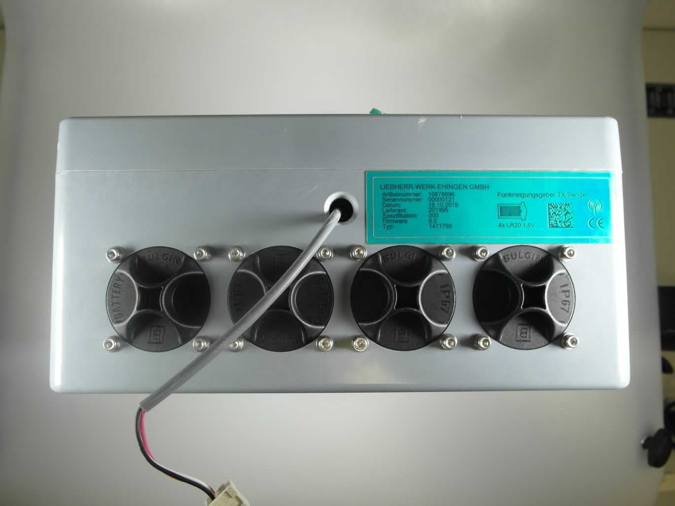
XK5-NGF24
Nov 02, 2020Radio inclination sensor
Equipment Class
DSS - Part 15 Spread Spectrum Transmitter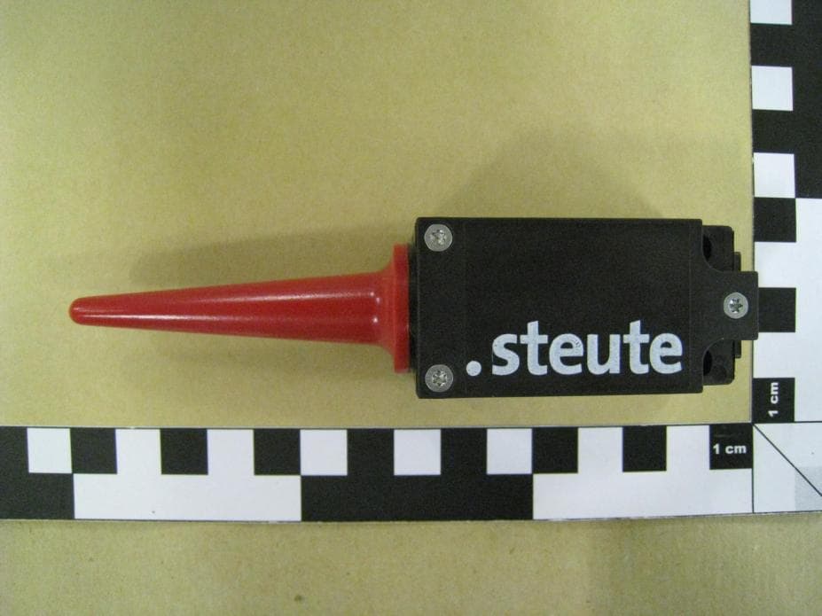
XK5-RF95SW915SR
May 24, 2012Radio Switch
Equipment Class
DTS - Digital Transmission System
XK5-RF95SW915LR
May 24, 2012Radio Switch
Equipment Class
DTS - Digital Transmission System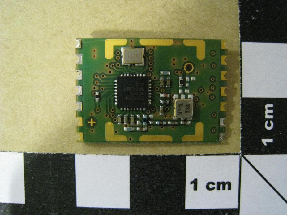
XK5-RFRXSW915
Apr 23, 2012RF Module
Equipment Class
DTS - Digital Transmission System