XK5-NGF24Radio inclination sensor
.steute Schaltgeraete GmbH & Co.KG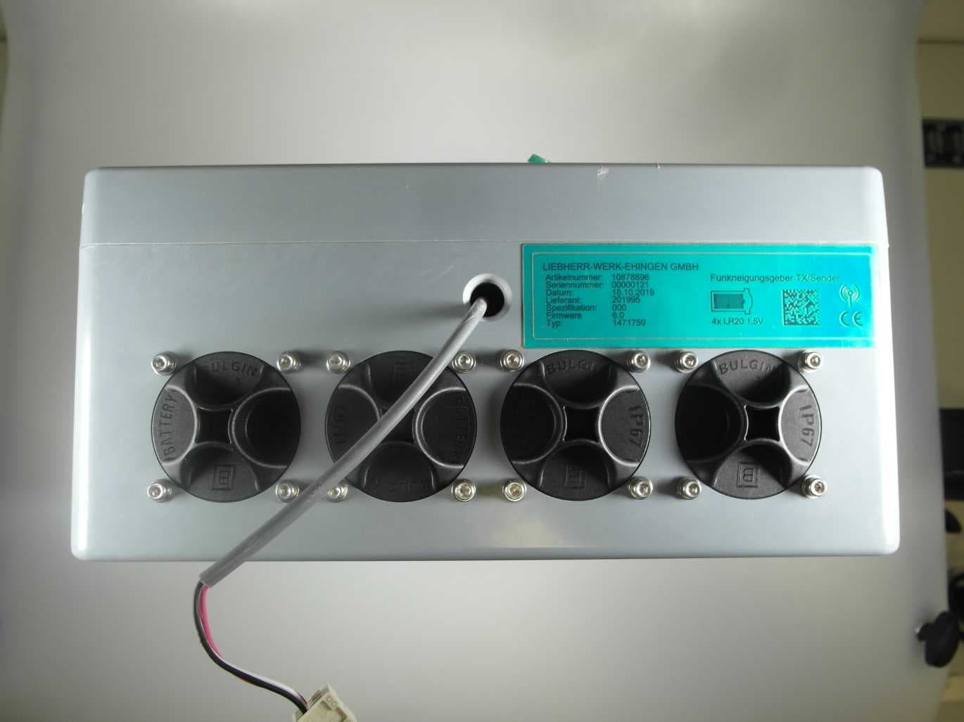
Click to zoom
Application Details
- Equipment Class
- DSS - Part 15 Spread Spectrum Transmitter
- Date of Grant
- Nov 02, 2020
- Application Purpose
- Original Equipment
- Date of Application
- Nov 02, 2020
- Equipment Note
- Radio inclination sensor
- Frequency Range
- 2401.40000000 - 2480.40000000
- Country
- Germany
Documents & Files
Document Text
Text extracted from the exhibit documents filed with the FCC. Open a document above to read the original.
Users Manual
steute Technologies GmbH & Co. KGBrückenstraße 91, 32584 Löhne, Germany, www.steute.com // RF Tx NGF ULR2.4-safe / RF Rx NGF ULR2.4-safe 1 / 10 Mounting and wiring instructions / Wireless tilting sensor English Use of the mounting and wiring instructions All actions described in these instructions may only be performed by qualified persons who have been trained and authorised by the operating company. 1. Read and understand these mounting and wiring instructions. 2. Comply with the valid occupational safety and accident prevention regulations. 3. Install and operate the device. Selection and installation of devices and their integration in control systems demand qualified knowledge of all the relevant laws, as well as the normative requirements of the machine manufacturer. Scope of delivery 1 device, mounting and wiring instructions, carton. Safety information = In this document, the warning triangle is used together with a signal word to indicate a hazardous situation. The signal words have the following meanings: NOTICE indicates a situation which may result in material damage. CAUTION indicates a situation which may result in minor or moderate injury. WARNING indicates a situation which may result in serious injury or death. DANGER indicates a situation which will result in serious injury or death. General information NOTICE After installation and during the operation of the NGF system in connection with the crane system, additional hazards may occur. These hazards go beyond the framework of these mounting and wiring instructions. They must be documented by the manufacturer of the overall system. NOTICE The NGF system is subject to specific preven- tive measures in terms of electromagnetic compatibility. Install and operate it in accord- ance with the used standards listed in the technical data section in this document. Intended use The wireless tilting sensor monitors the position of the bottom hook block of a crane and helps to hold it in a horizontal position. As a second application, it monitors the position of a load (e.g. with a parallel lift). NGF Tx NGF Rx steute Technologies GmbH & Co. KGBrückenstraße 91, 32584 Löhne, Germany, www.steute.com // RF Tx NGF ULR2.4-safe / RF Rx NGF ULR2.4-safe 2 / 10 Mounting and wiring instructions / Wireless tilting sensor English System components The system consists of a transmitter (Tx) and a receiver (Rx). The transmitter measures the angles and transmits the measured values via radio. The measured values are determined by two independent measuring systems. The radio link is a 2.4 GHz low-energy system. The transmitter is powered by batteries or accumulators. The two participants are paired in such a way that only one specific transmitter can communicate with the corresponding receiver. The receiver (Rx) is attached to the roller head and receives the meas- ured values via radio. The received data is then transmitted to the crane control via the LSB (Liebherr System Bus) interface. Product components RF Tx NGF ULR2.4-safe (transmitter) Legend 1Status LEDs (red/green) 2Pairing button (Tx only) 3Battery/battery compartment cover (Tx only) 4Battery insulation strip (Tx only) 5Bore holes, ø 6,5 mm RF Rx NGF ULR2.4-safe (receiver) Legend 6Enclosure ventilation 7M12 flange connector (Rx only) 8Enclosure cover screws 1 2 3 3 3 3 4 5 5 5 5 6 7 8 8 88 steute Technologies GmbH & Co. KGBrückenstraße 91, 32584 Löhne, Germany, www.steute.com // RF Tx NGF ULR2.4-safe / RF Rx NGF ULR2.4-safe 3 / 10 Mounting and wiring instructions / Wireless tilting sensor English Installation = WARNING Loose screws can cause parts to come loose and fall off. Tighten all cover screws hand-tight. The mechanical installation of the transmitter and receiver is the re- sponsibility of the system operator. The type of mounting and the mounting screws must be appropriate for the intended application. The maximum diameter of the bore hole is 6.5 mm. During installation, ensure that no moisture penetrates the sensor. Protection class IP65 is only achieved with a closed enclosure cover. For correct wiring of the receiver, read the »Technical Data« chapter of this manual. Battery = WARNING A wrong battery type may cause too short runtimes, wrong voltage or make the batteries not fit into the device. Use the NGF Tx with the specified battery type only. Do not mix old and new batteries. Make sure that the battery charge lasts long enough for the intended work. Use four 1.5 V alkaline batteries, type D, specified for industrial use (see technical data). Battery insertion Pairing = WARNING If the receiver (Rx) is paired with a different transmitter (Tx) than the intended one, the measured hook tilt may be wrong. This may lead to a dangerously inclined hook block. Make sure that the installed set of NGF Tx and Rx devices is paired correctly. To have transmitter and receiver communicate with each other, pair the devices once. Before the pairing, make sure that the following conditions apply: - Tx is powered up. - Tx is in Idle Mode. - Battery insulation strip has been removed. - Enclosure cover has been removed. - Rx is powered up. - Rx is connected to the LSB bus interface. - Rx and Tx are in radio range. steute Technologies GmbH & Co. KGBrückenstraße 91, 32584 Löhne, Germany, www.steute.com // RF Tx NGF ULR2.4-safe / RF Rx NGF ULR2.4-safe 4 / 10 Mounting and wiring instructions / Wireless tilting sensor English To set the devices to Pairing Mode: - Tx: press the pairing button on top of the inner case for >5 seconds. - Rx: send the LSB pairing command. The command must include the transmitter serial number (to be found on the Tx label). After both devices have been set to Pairing Mode, the receiver will send the new pairing ID to the transmitter. If this ID contains the cor- rect TX serial number, the transmitter will acknowledge the pairing and both devices fall back to Idle Mode. The new pairing ID is saved on both devices. Operation Modes RF Rx NGF ULR2.4-safe ModeMeaning Active Mod…
Text truncated - open the document above for the full version.
External Photos
Annex A 1-8822/19-01-01_AnnexA External photos of the Equipment Under Test This addendum is electronically signed and valid without handwritten signature. For verification of the electronic signatures, the public keys can be requested at the testing laboratory. Document authorized: Michael Dorongovski Lab Manager Radio Communications CTC advanced GmbHUntertuerkheimer Str. 6-10 66117 Saarbruecken / Germany Phone: +49 681 5 98 - 0 Fax: +49 681 5 98 - 9075 web: ctcadvanced.com e-mail: [email protected] Photos Photo 1: 1473157 device Photo 2: 1473157 device 2020-11-02Document No. 1-8822/19-01-01_AnnexA2/8 Photo 3: 1473157 device Photo 4: 1473157 device 2020-11-02Document No. 1-8822/19-01-01_AnnexA3/8 Photo 5: 1473157 device Photo 6: 1473157 device 2020-11-02Document No. 1-8822/19-01-01_AnnexA4/8 Photo 7: 1471759 device Photo 8: 1471759 device 2020-11-02Document No. 1-8822/19-01-01_AnnexA5/8 Photo 9: 1471759 device Photo 10: 1471759 device 2020-11-02Document No. 1-8822/19-01-01_AnnexA6/8 Photo 11: 1471759 device Photo 12: 1471759 device 2020-11-02Document No. 1-8822/19-01-01_AnnexA7/8 Document history VersionApplied changesDate of release initial release2020-11-02 - END OF DOCUMENT - 2020-11-02Document No. 1-8822/19-01-01_AnnexA8/8
ID Label/Location Info
Label Location Info - Radio System NGF24 Label_Location_Info_- _Radio_System_NGF24_Rev01_en.docx 1 von 2 23.10.2020 Meise-Reckefuss, Dirk Label Location Info - Radio System NGF24 Revision Author Datum Content of changes E-number 1 Meise-Reckefuss, Dirk 23.10.2020 Document created E-5843 Content 1 Label Location Info .................................................................................................................................... 1 2 Label size (exemplary for NGF 24 TX) ........................................................................................................ 1 3 Drawing of label location ........................................................................................................................... 2 1 Label Location Info The NGF 24 system is marked with an external and an internal label. All radio approval relevant information are located on the internal type label.The internal type plate is directly visible to the customer after opening the housing cover (required for commissioning). 2 Label size (exemplary for NGF 24 TX) Label Location Info - Radio System NGF24 Label_Location_Info_- _Radio_System_NGF24_Rev01_en.docx 2 von 2 23.10.2020 Meise-Reckefuss, Dirk 3 Drawing of label location Internal Label External Label
Internal Photos
Annex B 1-8822/19-01-01_AnnexB Internal photos of the Equipment Under Test This addendum is electronically signed and valid without handwritten signature. For verification of the electronic signatures, the public keys can be requested at the testing laboratory. Document authorized: Michael Dorongovski Lab Manager Radio Communications CTC advanced GmbHUntertuerkheimer Str. 6-10 66117 Saarbruecken / Germany Phone: +49 681 5 98 - 0 Fax: +49 681 5 98 - 9075 web: ctcadvanced.com e-mail: [email protected] Photos Photo 1: 1473157 device opened Photo 2: 1473157 device opened 2020-11-02Document No. 1-8822/19-01-01_AnnexB2/13 Photo 3: 1473157 device PCB front side view with shielding Photo 4: 1473157 device PCB front side view without shielding 2020-11-02Document No. 1-8822/19-01-01_AnnexB3/13 Photo 5: 1473157 device PCB back side view Photo 6: 1473157 device PCB back side view 2020-11-02Document No. 1-8822/19-01-01_AnnexB4/13 Photo 7: 1473157 device PCB back side view, antenna Photo 8: Non-RF parts of both hardware versions 2020-11-02Document No. 1-8822/19-01-01_AnnexB5/13 Photo 9: Non-RF parts of both hardware versions Photo 10: Non-RF parts of both hardware versions 2020-11-02Document No. 1-8822/19-01-01_AnnexB6/13 Photo 11: Non-RF parts of both hardware versions Photo 12: 1473157 device back cover 2020-11-02Document No. 1-8822/19-01-01_AnnexB7/13 Photo 13: 1471759 device Photo 14: 1471759 device battery 2020-11-02Document No. 1-8822/19-01-01_AnnexB8/13 Photo 15: 1471759 device opened Photo 16: 1471759 device opened 2020-11-02Document No. 1-8822/19-01-01_AnnexB9/13 Photo 17: 1471759 device PCB back side view Photo 18: 1471759 device opened 2020-11-02Document No. 1-8822/19-01-01_AnnexB10/13 Photo 19: 1471759 device PCB back side view Photo 20: 1471759 device PCB back side view, antenna 2020-11-02Document No. 1-8822/19-01-01_AnnexB11/13 Photo 21: 1471759 device PCB front side view with shielding Photo 22: 1471759 device PCB front side view without shielding 2020-11-02Document No. 1-8822/19-01-01_AnnexB12/13 Document history VersionApplied changesDate of release initial release2020-11-02 - END OF DOCUMENT - 2020-11-02Document No. 1-8822/19-01-01_AnnexB13/13
RF Exposure Info
© CTC advanced GmbH Page 1 of 3 BNetzA - CAB - 02/21 - 102 D - P L - 1 2 0 7 6 - 0 1 - 0 3 Maximum Permissible Exposure (MPE) & Exposure evaluation Report identification number: 1-8822/19-01-01 MPE (FCC_IC) Certification numbers and labeling requirements FCC ID XK5-NGF24 IC number 5158A-NGF24 HVIN (Hardware Version Identification Number) 1473157 1471759 PMN (Product Marketing Name) Funkneigungsgeber (NGF) FVIN (Firmware Version Identification Number) -/- HMN (Host Marketing Name) -/- This report is electronically signed and valid without handwriting signature. For verification of the electronic signatures, the public keys can be requested at the testing laboratory. Document authorised: Alexander Hnatovskiy Mihail Dorongovskij Lab Manager Lab Manager Radio Communications Radio Communications Report no.: 1-8822/19-01-01 © CTC advanced GmbH Page 2 of 3 EUT technologies: Technologies: Max antenna gain Max conducted output power 2.4 GHz Proprietary Transceiver 7.6 dBi 17.6 dBm NOTE: Values taken from from CTC advanced test report 1-8822/19-01-05. Prediction of MPE limit at given distance - FCC Equation from page 18 of OET Bulletin 65, Edition 97-01 S = PG / 4π R 2 where: S = Power density P = Power input to the antenna G = Antenna gain R = Distance to the center of radiation of the antenna PG = Output Power including antenna gain The table below is excerpted from Table 1B of 47 CFR 1.1310 titled “Limits for Maximum Permissible Exposure (MPE), Limits for General Population/Uncontrolled Exposure” Frequency Range (MHz) Power Density (mW/cm 2 ) Averaging Time (minutes) 300 -1500 f/1500 30 1500 - 100000 1.0 30 where f = Frequency (MHz) Prediction: worst case Technology Proprietary @ 2450 MHz Max power input to the antenna 17.6 dBm Distance 20 cm Antenna gain 7.6 dBi MPE limit for uncontrolled exposure 1 mW/cm 2 Calculated Power density: 0.0659 mW/cm² This prediction demonstrates the following: The power density levels for FCC at a distance of 20 cm are below the maximum levels allowed by regulations. Report no.: 1-8822/19-01-01 © CTC advanced GmbH Page 3 of 3 Prediction of MPE limit at given distance - IC RSS-102, Issue 5, 2.5.2 RF exposure evaluation is required if the separation distance between the user and/or bystander and the device’s radiating element is greater than 20 cm, except when the device operates as follows: • below 20 MHz and the source-based, time-averaged maximum e.i.r.p. of the device is equal to or less than 1 W (adjusted for tune-up tolerance); • at or above 20 MHz and below 48 MHz and the source-based, time-averaged maximum e.i.r.p. of the device is equal to or less than 4.49/ƒ 0.5 W (adjusted for tune-up tolerance), where ƒ is in MHz; • at or above 48 MHz and below 300 MHz and the source-based, time-averaged maximum e.i.r.p. of the device is equal to or less than 0.6 W (adjusted for tune-up tolerance); • at or above 300 MHz and below 6 GHz and the source-based, time-averaged maximum e.i.r.p. of the device is equal to or less than 1.31 x 10 -2 ƒ 0.6834 W (adjusted for tune-up tolerance), where ƒ is in MHz; • at or above 6 GHz and the source-based, time-averaged maximum e.i.r.p. of the device is equal to or less than 5 W (adjusted for tune-up tolerance). Prediction: worst case Conclusion: RF exposure evaluation is not required. For applications where minimum distance to radiating element is 20cm Annex C of RSS-102 should be filled out. 0.3 - 6 GHz Technology Proprietary 2.4 GHz Frequency 2450 MHz P Max power input to the antenna 17.6 dBm R Distance 20 cm G Antenna gain 7.6 dBi Maximum EIRP 331.1 mW Exclusion Limit from above: 2.71 W
Test Report
BNetzA - CAB - 02/21 - 102 TEST REPORT Test report no.: 1-8822/19-01-05 Testing laboratory Applicant CTC advanced GmbH Untertuerkheimer Strasse 6 – 10 66117 Saarbruecken / Germany Phone: + 49 681 5 98 - 0 Fax: + 49 681 5 98 - 9075 Internet: http://www.ctcadvanced.com e-mail: [email protected] Accredited Testing Laboratory: The testing laboratory (area of testing) is accredited according to DIN EN ISO/IEC 17025 (2018-03) by the Deutsche Akkreditierungsstelle GmbH (DAkkS) The accreditation is valid for the scope of testing procedures as stated in the accreditation certificate starting with the registration number: D-PL-12076-01. steute Technologies GmbH & Co. KG Brückenstraße 91 32584 Löhne / GERMANY Phone: +49 (0) 5731 745 - 249 Contact: Dirk Meise-Reckefuß e-mail: [email protected] Phone: +49 5731 745-296 Manufacturer steute Technologies GmbH & Co. KG Brückenstraße 91 32584 Löhne / GERMANY Test standard/s FCC - Title 47 CFR Part 15 FCC - Title 47 of the Code of Federal Regulations; Chapter I; Part 15 - Radio frequency devices RSS - 247 Issue 2 Digital Transmission Systems (DTSs), Frequency Hopping Systems (FHSs) and Licence - Exempt Local Area Network (LE-LAN) Devices For further applied test standards please refer to section 3 of this test report. Test Item Kind of test item: 2.4 GHz proprietary RF system Model name: TX NGF ULR2.4-safe; RX NGF ULR2.4-safe FCC ID: XK5-NGF24 IC: 5158A-NGF24 Frequency: DTS band 2400 MHz to 2483.5 MHz Technology tested: Proprietary Antenna: Two integrated antennas Power supply: 24.0 V DC by external power supply Temperature range: -40°C to +70°C This test report is electronically signed and valid without handwritten signature. For verification of the electronic signatures, the public keys can be requested at the testing laboratory. Test report authorized: Test performed: Marco Bertolino Mihail Dorongovskij Lab Manager Lab Manager Radio Communications Radio Communications Test report no.: 1-8822/19-01-05 © CTC advanced GmbH Page 2 of 60 1 Table of contents 1 Table of contents ............................................................................................................................................. 2 2 General information ......................................................................................................................................... 4 2.1 Notes and disclaimer ............................................................................................................................ 4 2.2 Application details ................................................................................................................................ 4 2.3 Test laboratories sub-contracted ......................................................................................................... 4 3 Test standard/s, references and accreditations .............................................................................................. 5 4 Reporting statements of conformity – decision rule ...................................................................................... 6 5 Test environment ............................................................................................................................................. 7 6 Test item .......................................................................................................................................................... 7 6.1 General description ............................................................................................................................... 7 6.2 Additional information .......................................................................................................................... 7 7 Sequence of testing ......................................................................................................................................... 8 7.1 Sequence of testing radiated spurious 9 kHz to 30 MHz ..................................................................... 8 7.2 Sequence of testing radiated spurious 30 MHz to 1 GHz .................................................................... 9 7.3 Sequence of testing radiated spurious 1 GHz to 18 GHz ................................................................... 10 7.4 Sequence of testing radiated spurious above 18 GHz ....................................................................... 11 8 Description of the test setup.......................................................................................................................... 12 8.1 Shielded semi anechoic chamber ....................................................................................................... 13 8.2 Shielded fully anechoic chamber ........................................................................................................ 15 8.3 Radiated measurements > 18 GHz ...................................................................................................... 16 8.4 Conducted measurements Bluetooth system .................................................................................... 17 8.5 Shielded fully anechoic chamber ........................................................................................................ 18 9 Measurement uncertainty .............................................................................................................................. 19 10 Summary of measurement results ......................................................................................................... 20 11 Additional comments .............................................................................................................................. 21 12 Measurement results .............................................................................................................................. 23 12.1 Antenna gain ..................................................................................................…
Text truncated - open the document above for the full version.
Test Report
Measurement Results 1-8822/19-01-05_log1_conducted Test logging This addendum is electronically signed and valid without handwritten signature. For verification of the electronic signatures, the public keys can be requested at the testing laboratory. Document authorized: Mihail Dorongovskij Lab Manager Radio Communications CTC advanced GmbHUntertuerkheimer Strasse 6-10 66117 Saarbruecken / Germany Phone: +49 681 5 98 - 0 Fax: +49 681 5 98 - 9075 web: ctcadvanced.com e-mail: [email protected] Table of Content IUT Summary3 1. FCC Part 15.247 Bandwidth 99PCT-20dB ~ Generic 2G44 2. FCC Part 15.247 Bandwidth 99PCT-20dB ~ Generic 2G47 3. FCC Part 15.247 Bandwidth 99PCT-20dB ~ Generic 2G410 4. FCC Part 15.247 Bandwidth 99PCT-20dB ~ Generic 2G413 5. FCC Part 15.247 Bandwidth 99PCT-20dB ~ Generic 2G416 6. FCC Part 15.247 Bandwidth 99PCT-20dB ~ Generic 2G419 7. FCC Part 15.247 Bandwidth 99PCT-20dB ~ Generic 2G422 8. FCC Part 15.247 Bandwidth 99PCT-20dB ~ Generic 2G425 9. FCC Part 15.247 Bandwidth 99PCT-20dB ~ Generic 2G428 10. FCC Part 15.247 Bandwidth 99PCT-20dB ~ Generic 2G431 11. FCC Part 15.247 Bandwidth 99PCT-20dB ~ Generic 2G434 12. FCC Part 15.247 TX Spurious Conduced ~ Generic 2G437 13. FCC Part 15.247 TX Spurious Conduced ~ Generic 2G439 14. FCC Part 15.247 TX Spurious Conduced ~ Generic 2G441 15. FCC Part 15.247 TX Spurious Conduced ~ Generic 2G443 16. FCC Part 15.247 TX Spurious Conduced ~ Generic 2G445 17. FCC Part 15.247 TX Spurious Conduced ~ Generic 2G447 18. FCC Part 15.247 TX Spurious Conduced ~ Generic 2G449 19. FCC Part 15.247 TX Spurious Conduced ~ Generic 2G451 20. FCC Part 15.247 TX Spurious Conduced ~ Generic 2G453 21. FCC Part 15.247 TX Spurious Conduced ~ Generic 2G455 22. FCC Part 15.247 TX Spurious Conduced ~ Generic 2G457 23. Common2G4 Peak OP 3MHz/3MHz ~ Generic 2G459 24. FCC Part 15.247 Maximum Peak Conducted Output Power FHSS ~ Generic 2G463 25. FCC Part 15.247 Maximum Peak Conducted Output Power FHSS ~ Generic 2G465 26. FCC Part 15.247 Maximum Peak Conducted Output Power FHSS ~ Generic 2G467 27. FCC Part 15.247 Maximum Peak Conducted Output Power FHSS ~ Generic 2G469 28. FCC Part 15.247 Maximum Peak Conducted Output Power FHSS ~ Generic 2G471 29. FCC Part 15.247 Maximum Peak Conducted Output Power FHSS ~ Generic 2G473 30. FCC Part 15.247 Maximum Peak Conducted Output Power FHSS ~ Generic 2G475 31. FCC Part 15.247 Maximum Peak Conducted Output Power FHSS ~ Generic 2G477 32. FCC Part 15.247 Maximum Peak Conducted Output Power FHSS ~ Generic 2G479 33. FCC Part 15.247 Maximum Peak Conducted Output Power FHSS ~ Generic 2G481 34. FCC Part 15.247 Maximum Peak Conducted Output Power FHSS ~ Generic 2G483 35. Hardcopy Spectrum Analyzer ~ 85 36. Hardcopy Spectrum Analyzer ~ 87 37. Hardcopy Spectrum Analyzer ~ 89 38. Hardcopy Spectrum Analyzer ~ 91 39. Hardcopy Spectrum Analyzer ~ 93 40. Hardcopy Spectrum Analyzer ~ 95 41. Hardcopy Spectrum Analyzer ~ 97 42. Hardcopy Spectrum Analyzer ~ 99 43. Hardcopy Spectrum Analyzer ~ 101 44. Hardcopy Spectrum Analyzer ~ 103 45. Hardcopy Spectrum Analyzer ~ 105 Document No. 1-8822/19-01-05_log1_conducted2/106 IUT Summary IUT DEFINITION & Common settings Manufacturersteute Technologies GmbH & Co KG TypeTX NGF ULR2.4-safe; RX NGF ULR2.4-safe Serial No. | Setup No.1473157 / SerNo: 00034 (0x22) | 1.0 SW Version | HW VersionV01.07 | NI Comment 1 | 2Chain A Tlow | Tmid | Thigh [°C] -40 | 20 | 70 Vlow | Vmid | Vhigh [V] @Imax [A] 24.0 | 24.0 | 24.0 @1 Auto Control enabled Power Supply | Climatic BoxNo | No Antenna Gain [dBi] (only considered if explicitly mentioned in testresult)0 Additional Path Loss [dB]0 IUT Common Settings 2G4 Hopping supported Yes Burst length [ms]10 Nominal Bandwidth [MHz]1.5 User InteractionNo Document No. 1-8822/19-01-05_log1_conducted3/106 1. FCC Part 15.247 Bandwidth 99PCT-20dB ~ Generic 2G4 Test References TC Start06.08.2020 11:44:22 Ambit Temp [°C] | Humidity [rel%] 25.3 | 37 System Version1.0.0.49 Test SpecificationFCC Part 15.247 Test Method Class / TC VersionTC_VM_FCC15247_Bandwidth_99PCT_20dB_DTS_FHSS_V01 Version: 0.0.2 My DescriptionFCC 15.247 Bandwidth 99PCT - 20DB FHSS - Generic 2G4 Add. Information Test Parameter Technology to testGeneric 2G4 Antenna Port used1 Temperaturemid Voltagemid Frequency low to testTrue | Freq [MHz] 2401.4 Frequency mid to testFalse | Freq [MHz] 2440.4 Frequency high to testFalse | Freq [MHz] 2480.4 Switched PathIUT - SignalingUnit - SpectrumAnalyzer Devices in use | SA: Rohde&Schwarz,FSV-30,1321.3008K30/103170,3.60 Document No. 1-8822/19-01-05_log1_conducted4/106 Test at TX 2401.4 MHz READ SA SETTINGS: RefLevel [dBm] | RefLevelOffset [dB] | InpAtt [dB]14.22 | 10.21 | 20 Start [MHz] | Stop [MHz]2399.900 | 2402.900 RBW [MHz] | VBW [MHz]0.030000 | 0.100000 Detector | TraceModePOS | MAXH Sweep: Time [ms] | Count | Points per Section | Type50 | 200 | 10001 | SWE RESULT Test DescriptionLower LimitUpper LimitMeasuredUnitVerdict Bandwidth 99%------422kHzINFO T1 99%2400.000000---2401.1960MHzPASS T2 99%---2483.5000002401.6178MHzPASS Plot_FCC Part 15.247 Bandwidth 99PCT-20dB ~ Generic 2G4 99PCT_06082020_114451.png Plot_FCC Part 15.247 Bandwidth 99PCT-20dB ~ Generic 2G4_06082020_114455.png RESULT Test DescriptionLower LimitUpper LimitMeasuredUnitVerdict Bandwidth 20dB------429kHzINFO T1 20DB2400.000000---2401.1918MHzPASS T2 20dB---2483.5000002401.6208MHzPASS Document No. 1-8822/19-01-05_log1_conducted5/106 Plot_FCC Part 15.247 Bandwidth 99PCT-20dB ~ Generic 2G4 20dB_06082020_114500.png Plot_FCC Part 15.247 Bandwidth 99PCT-20dB ~ Generic 2G4_06082020_114504.png TEST FINISHED General Verdict06.08.2020 11:45:05 / RT: 43 sPASS Document No. 1-8822/19-01-05_log1_conducted6/106 2. FCC Part 15.247 Bandwidth 99PCT-20dB ~ Generic 2G4 Test References TC Start06.08.2020 12:28:12 Ambit Temp [°C] | Humidity [rel%] 25.3 | 38 System Version1.0.0.49 Test SpecificationFCC Part 15.247 Test Method Class / TC VersionTC_VM_FCC15247_Bandwidth_99PCT_20dB_DTS_FHSS_V01 Version: 0.0.2 My DescriptionFCC 15.247 Bandwidth …
Text truncated - open the document above for the full version.
Test Report
Measurement Results 1-8822/19-01-05_log2_conducted Test logging This addendum is electronically signed and valid without handwritten signature. For verification of the electronic signatures, the public keys can be requested at the testing laboratory. Document authorized: Mihail Dorongovskij Lab Manager Radio Communications CTC advanced GmbHUntertuerkheimer Strasse 6-10 66117 Saarbruecken / Germany Phone: +49 681 5 98 - 0 Fax: +49 681 5 98 - 9075 web: ctcadvanced.com e-mail: [email protected] Table of Content IUT Summary3 1. FCC Part 15.247 Bandwidth 99PCT-20dB ~ Generic 2G44 2. FCC Part 15.247 Bandwidth 99PCT-20dB ~ Generic 2G47 3. FCC Part 15.247 Bandwidth 99PCT-20dB ~ Generic 2G410 4. FCC Part 15.247 Bandwidth 99PCT-20dB ~ Generic 2G413 5. FCC Part 15.247 Bandwidth 99PCT-20dB ~ Generic 2G416 6. FCC Part 15.247 Bandwidth 99PCT-20dB ~ Generic 2G419 7. FCC Part 15.247 Bandwidth 99PCT-20dB ~ Generic 2G422 8. FCC Part 15.247 Bandwidth 99PCT-20dB ~ Generic 2G425 9. FCC Part 15.247 Bandwidth 99PCT-20dB ~ Generic 2G428 10. FCC Part 15.247 Bandwidth 99PCT-20dB ~ Generic 2G431 11. FCC Part 15.247 TX Spurious Conduced ~ Generic 2G434 12. FCC Part 15.247 TX Spurious Conduced ~ Generic 2G436 13. FCC Part 15.247 TX Spurious Conduced ~ Generic 2G438 14. FCC Part 15.247 TX Spurious Conduced ~ Generic 2G440 15. FCC Part 15.247 TX Spurious Conduced ~ Generic 2G442 16. FCC Part 15.247 TX Spurious Conduced ~ Generic 2G444 17. FCC Part 15.247 TX Spurious Conduced ~ Generic 2G446 18. FCC Part 15.247 TX Spurious Conduced ~ Generic 2G448 19. FCC Part 15.247 TX Spurious Conduced ~ Generic 2G450 20. FCC Part 15.247 TX Spurious Conduced ~ Generic 2G452 21. FCC Part 15.247 Maximum Peak Conducted Output Power FHSS ~ Generic 2G454 22. FCC Part 15.247 Maximum Peak Conducted Output Power FHSS ~ Generic 2G456 23. FCC Part 15.247 Maximum Peak Conducted Output Power FHSS ~ Generic 2G458 24. FCC Part 15.247 Maximum Peak Conducted Output Power FHSS ~ Generic 2G460 25. FCC Part 15.247 Maximum Peak Conducted Output Power FHSS ~ Generic 2G462 26. FCC Part 15.247 Maximum Peak Conducted Output Power FHSS ~ Generic 2G464 27. FCC Part 15.247 Maximum Peak Conducted Output Power FHSS ~ Generic 2G466 28. FCC Part 15.247 Maximum Peak Conducted Output Power FHSS ~ Generic 2G468 29. FCC Part 15.247 Maximum Peak Conducted Output Power FHSS ~ Generic 2G470 30. FCC Part 15.247 Maximum Peak Conducted Output Power FHSS ~ Generic 2G472 31. Hardcopy Spectrum Analyzer ~ 74 32. Hardcopy Spectrum Analyzer ~ 76 33. Hardcopy Spectrum Analyzer ~ 78 34. Hardcopy Spectrum Analyzer ~ 80 35. Hardcopy Spectrum Analyzer ~ 82 36. Hardcopy Spectrum Analyzer ~ 84 37. Hardcopy Spectrum Analyzer ~ 86 38. Hardcopy Spectrum Analyzer ~ 88 39. Hardcopy Spectrum Analyzer ~ 90 40. Hardcopy Spectrum Analyzer ~ 92 41. Hardcopy Spectrum Analyzer ~ 94 Document No. 1-8822/19-01-05_log2_conducted2/95 IUT Summary IUT DEFINITION & Common settings Manufacturersteute Technologies GmbH & Co KG TypeTX NGF ULR2.4-safe; RX NGF ULR2.4-safe Serial No. | Setup No.1473157 / SerNo: 00034 (0x22) | 1.0 SW Version | HW VersionV01.07 | NI Comment 1 | 2Chain B Tlow | Tmid | Thigh [°C] -40 | 20 | 70 Vlow | Vmid | Vhigh [V] @Imax [A] 24.0 | 24.0 | 24.0 @1 Auto Control enabled Power Supply | Climatic BoxNo | No Antenna Gain [dBi] (only considered if explicitly mentioned in testresult)0 Additional Path Loss [dB]0 IUT Common Settings 2G4 Hopping supported Yes Burst length [ms]10 Nominal Bandwidth [MHz]1.5 User InteractionNo Document No. 1-8822/19-01-05_log2_conducted3/95 1. FCC Part 15.247 Bandwidth 99PCT-20dB ~ Generic 2G4 Test References TC Start06.08.2020 16:19:34 Ambit Temp [°C] | Humidity [rel%] 25.8 | 38 …
Text truncated - open the document above for the full version.
Contact Information
Applicant
Marc Schmidt
Test Firm
cetecom advanced GmbHGerald Schmidt
Technical Specifications
| # | Rule Parts | Frequency Range | Power Output |
|---|---|---|---|
| 1 | 15C | 2.40 GHz - 2.48 GHz | 57.54 mW |
Other Applications from .steute Schaltgeraete GmbH & Co.KG
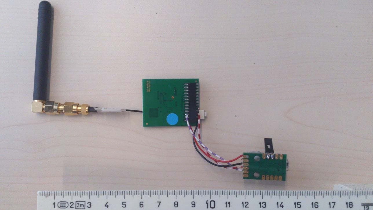
XK5-BMPSR
Jul 06, 2015BMPSR Module
Equipment Class
DSS - Part 15 Spread Spectrum Transmitter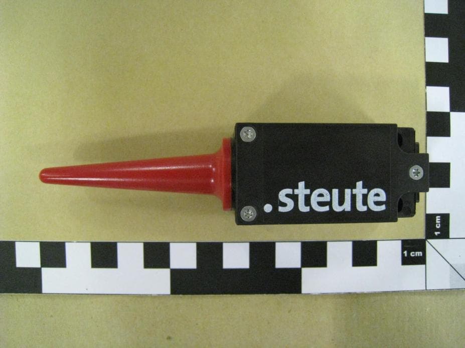
XK5-RF95SW915SR
May 24, 2012Radio Switch
Equipment Class
DTS - Digital Transmission System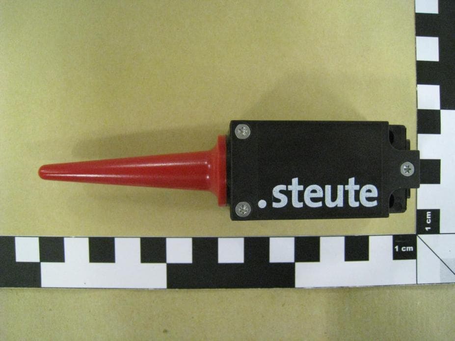
XK5-RF95SW915LR
May 24, 2012Radio Switch
Equipment Class
DTS - Digital Transmission System
XK5-RFRXSW915
Apr 23, 2012RF Module
Equipment Class
DTS - Digital Transmission System