XLG-FS-GF8018-port RFID Smart Reader (902-928MHz)
FAVITE Inc.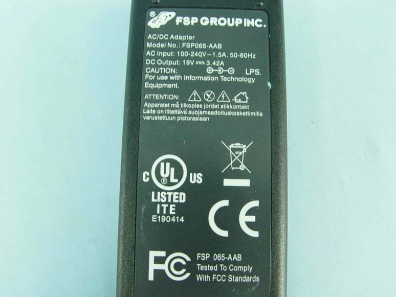
Click to zoom
Application Details
- Equipment Class
- DSS - Part 15 Spread Spectrum Transmitter
- Date of Grant
- Jun 02, 2010
- Application Purpose
- Original Equipment
- Date of Application
- Jun 02, 2010
- Equipment Note
- 8-port RFID Smart Reader (902-928MHz)
- Frequency Range
- 902.75000000 - 927.25000000
- Company
- FAVITE Inc.
- Country
- Taiwan
Documents & Files
Document Text
Text extracted from the exhibit documents filed with the FCC. Open a document above to read the original.
Users Manual
FS-GF801 User’s Manual Favite Inc. 2 Table of Contents CHAPTER 1 .......................................................................................................................... 3 Introduction ................................................................................................................ 3 RFID Reader Overview ........................................................................................................ 3 EPC Class 1 UHF RFID Tags .................................................................................................. 3 Requirements ...................................................................................................................... 4 Module Specifications ......................................................................................................... 5 Mechanical: Reader Physical Size ....................................................................................... 6 Antenna Port Terminal Interface: Mono‐Static Mode ....................................................... 9 Antenna Port Terminal Interface: Bi‐Static Mode .............................................................. 9 Reader I/O Terminal .......................................................................................................... 10 GPIO Port Terminal Interface ............................................................................................ 11 GPIO Port Terminal Circuit Diagram ................................................................................. 12 CHAPTER 2 ........................................................................................................................ 14 Reader Hardware Installation and Operation ......................................................... 14 Receiving the RFID Reader ................................................................................................ 14 Diagnostic LEDs ................................................................................................................. 17 Antenna Panel ................................................................................................................... 18 Demonstration Software Guide ........................................................................................ 19 3 CHAPTER 1 Introduction This Hardware Setup Guide provides instructions for installing and operating the FS-GF801 RFID Readers. This document is designed for use by RFID system integrators and software developers - those who wish to develop software products and extended systems that take full advantage of the RFID Reader's capabilities. Included with each reader or developer kit are the Favite RFID Reader Software Developer’s Kit and User Documentation on FTP Server or download in Favite web ( http://rfid.favite.com/download_1.asp . ) RFID Reader Overview FS-GF801, one of FAVITE RFID reader family, is an Intel ATOM CPU based smart reader. The FS-GM801 is embedded with Impinj R2000 chip and compliant with EPC Class1 Gen2 Dense Reader mode (DRM) / ISO 18000-6C. The FS-GF801 is equipped with 8 SMA RF antenna ports which could support 8 mono-static antennas or 4 pairs of bi-static antennas, providing support for the richest enterprise applications. With the powerful combination of an Intel ATOM N270 1.6GHz CPU and 1GB memory (up to 2GB), the FS-GF801 is the smartest RFID reader available, capable of running complex RFID applications, delivering faster processing and localized intelligence. The RFID Reader is delivered with the following components and accessories: One (1) RFID Smart Reader. One (1) power supply Windows XP embedded operation system (optional). EPC Class 1 UHF RFID Tags The Favite FS-GF801 RFID reader is designed to read and program any EPC Class 1 Generation 2 tag (see below) and issue event reports to a host computer system. The reader is also designed to read and program Class 1 Generation 2 tags. Class 1 Generation 2 tags are “passive” devices meaning they do not have a battery or other onboard power source. They are powered solely by the RF energy transmitted by an RFID reader. They communicate with the reader through backscatter modulation in which the tags do not actually transmit RF energy. Instead, they change their reflective characteristics in a systematic way and reflect RF energy back to the reader. An analogy to this is the way you can use a mirror to transmit information by reflecting light from the Sun. Favite Inc. manufactures user-programmable EPC Class 1 Generation 2 tags compliant with all key commercial and DoD mandates. Favite offers a variety of designs capable of delivering optimal performance worldwide, including Europe and Asia. 4 For more information about RFID tags from Favite Inc., please visit our website at http://rfid.favitete.com. Requirements To interface with the RFID Reader you will need the following: Standard DC 19V, 3.42A Power supply and Host software (Favite demo software or your own custom software implement by Favite Software Development Kit. 5 Module Specifications System Host Interface (USB / UART/ RS232 / LED / Reset / Debug Port / GPIO / SAMBA / VCC in / GND) Chipset PHY: Impinj R2000 MAC: ATMEL AT91SAM7S-256 Operating Voltages 12.0V+/-5% or 5.0V+/-5% (option) DC Power 12V:1.5A @ 30dBm; 5V:3A @ 30dBm Protocol RFID Protocol Support EPC Gen 2 ISO 18000-6C Support EPC DRM Yes (with DRM Filter) SW Switchable RF Frequency US: 902 ~ 928MHz(FHSS) EU: 865 ~ 868MHz Demodulation PR-ASK Modulation Depth 90% nominal Data Encoding FM0 or Miller code Bit Rate Supports uplink data rates of up to 640 Kbps TX Output power 5 ~ 30dBm in 1dB step Antenna Type 8 Port Mono-static and 4 Port Bi-static SW selectable Antenna connector 8 SMA connectors Regulatory and Environmental Compliance EMC certification FCC 47 CFG Ch.1 Part 15 (US) ETSI EN 302 208-1 (V1.1.1) (EU) Temperature Range Operating: 0 ~ 55 degree C, Storage: -20 ~ 85 degree C Humidity 10% ~ 85% Non-condensing Software Dri…
Text truncated - open the document above for the full version.
Cover Letter(s)
FCC ID: XLG-FS-GF801 Report No.: RF990414C05 Modular Approval Request Letter Bureau Veritas Consumer Products Services (H.K.) Ltd., Taoyuan Branch May 28, 2010 Dear Application Examiner, Favite Inc., It’s a 8-port RFID Smart Reader (902-928MHz), FCC ID: XLG-FS-GF801 would like to have your authorization as a modular device. The requirements of section 15.212 of FCC rules have been met and shown on the following statements. 1. “The modular transmitter must have its own RF shielding.”: The radio portion of this module has been shielded, please see exhibition External Photo. 2. “The modular transmitter must have buffered modulation/data inputs.” The EUT has buffered data inputs, it is integrated in R2000. 3. “The modular transmitter must have its own power supply regulation.” The part number of this regulator is PS34 , PS45 , PS56, TPS79333DBVRG4 4. “The modular transmitter must comply with the antenna requirements of section 15.203 and 15.204(C).” The EUT meets the FCC antenna requirements. The spurious emission, unique antenna connector and photo of antennas are shown in the test report. 5. “The modular transmitter must be tested in a stand-alone configuration” The EUT was tested in a stand-alone configuration via an MINI USB CABLE. Please see section Photographs of Test Configuration in the test report, the EUT was connected with this cable. 6. “The modular transmitter must be labeled with its own FCC ID number.” Please see exhibition Label Sample for the FCC ID of this module. And also in the exhibition Users Manual, there are instructions give to the OEM on how to label the end product. FCC ID: XLG-FS-GF801 Report No.: RF990414C05 7. “The modular transmitter must comply with any specific rule or operating requirements applicable to the transmitter and the manufacturer must provide adequate instructions along with the module to explain any such requirements.” The EUT is compliant with all applicable FCC rules. Detail instructions for maintaining compliance are given in the Users Manual. 8. “The modular transmitter must comply with any applicable RF exposure requirements.” The EUT is compliant with all applicable RF exposure requirements. RF Exposure is addressed in the RF exposure exhibition. Please contact me if you have any further questions. Thanks for your attention. Best Regards, signature Gary Chang Assistant Manager Bureau Veritas Consumer Products Services (H.K.) Ltd., Taoyuan Branch
Cover Letter(s)
FAVITE Inc. No.176,Taihe Rd., Jhubei City, Hsinchu County 30267, Taiwan Professional Installation Attestation Date: 2010/5/28 To Whom It May Concern: Please be advised that due to the unique Market and function targeted by this product, this product will need special trained professional in configuring and installing the product. We hereby declare that the product will be distributed through controlled distribution channel which has special trained professional to install this product and will not be sold directly to the general public through retail store. Thank you for your attention. Yours sincerely,
External Photos
Page 1 CONSTRUCTION PHOTOS OF EUT Page 2 Page 3 Page 4 Page 5
ID Label/Location Info
Design for GF801 Reader module Logo Favite Inc.UHF ReaderModel Name: FS-GF801EPC Class 1 Gen 2FCC Frequency Range: 902-928MHzETSI Frequency Range: 865-867MHzhttp://rfid.favite.comTel:+886-3-5533880 web:www.favite.com FCC ID: XLG-FS-GF801 Favite Inc.UHF ReaderModel Name: FS-GF801EPC Class 1 Gen 2FCC Frequency Range: 902-928MHzETSI Frequency Range: 865-867MHzhttp://rfid.favite.comTel:+886-3-5533880 www.favite.com FCC ID: XLG-FS-GF801 40mm 50mm 34mm 34mm
Internal Photos
Page 6 Page 7 Page 8 Page 9
Operational Description
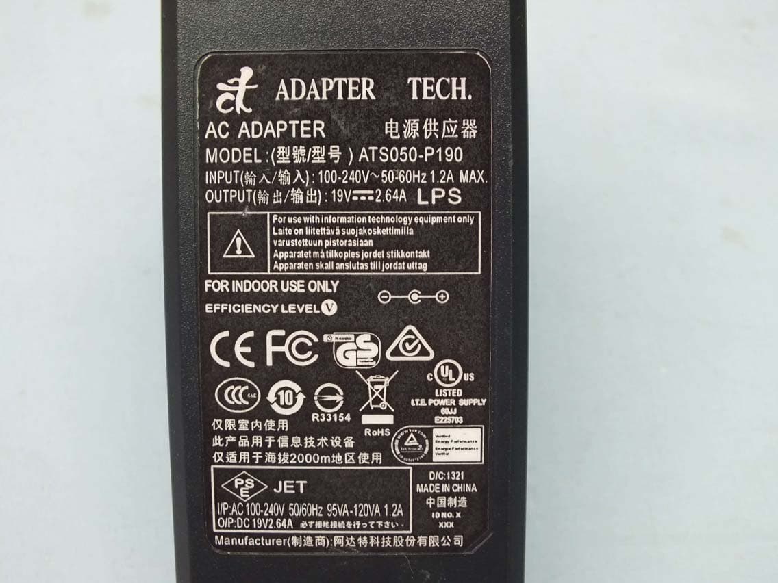
FCC ID: XLG-FS-GF801 Report No.: RF990414C05 OPERATIONAL DESCRIPTION FS-GF801, one of FAVITE RFID reader family, is an Intel ATOM CPU based smart reader. The FS-GM801 is embedded with Impinj R2000 chip and compliant with EPC Class1 Gen2 Dense Reader mode (DRM) / ISO 18000-6C. The FS-GF801 is equipped with 8 SMA RF antenna ports which could support 8 mono-static antennas or 4 pairs of bi-static antennas, providing support for the richest enterprise applications. The FS-GF801 is the smartest RFID reader available, capable of running complex RFID applications, delivering faster processing and localized intelligence. The transmitter of the EUT is powered by 19Vdc from an adapter. The antenna is patch antenna with SMA connector. For more detailed instruction, please take a look at the user’s manual.
RF Exposure Info
Report No.: SA990414C05 Report Format Version 3.0.1. 1 RF EXPOSURE REPORT REPORT NO.: SA990414C05 MODEL NO.: FS-GF801 FCC ID: XLG-FS-GF801 ACCORDING: FCC Guidelines for Human Exposure IEEE C95.1 APPLICANT: Favite Inc. ADDRESS: No. 176, Taihe Road, Jhubei City,Hsinchu County 30267, Taiwan ISSUED BY: Bureau Veritas Consumer Products Services (H.K.) Ltd., Taoyuan Branch LAB ADDRESS: No. 47, 14th Ling, Chia Pau Tsuen, Lin Kou Hsiang, Taipei Hsien 244, Taiwan, R.O.C. TEST LOCATION: No. 19, Hwa Ya 2nd Rd, Wen Hwa Tsuen, Kwei Shan Hsiang, Taoyuan Hsien 333, Taiwan, R.O.C. Report No.: SA990414C05 Report Format Version 3.0.1. 2 1. RF EXPOSURE LIMIT LIMITS FOR MAXIMUM PERMISSIBLE EXPOSURE (MPE) FREQUENCY RANGE (MHz) ELECTRIC FIELD STRENGTH (V/m) MAGNETIC FIELD STRENGTH (A/m) POWER DENSITY (mW/cm 2 ) AVERAGE TIME (minutes) LIMITS FOR GENERAL POPULATION / UNCONTROLLED EXPOSURE 300-1500 ... ... F/1500 30 1500-100,000 ... ... 1.0 30 F = Frequency in MHz 2. MPE CALCULATION FORMULA Pd = (Pout*G) / (4*pi*r2) where Pd = power density in mW/cm2 Pout = output power to antenna in mW G = gain of antenna in linear scale Pi = 3.1416 R = distance between observation point and center of the radiator in cm 3. CLASSIFICATION The antenna of this product, under normal use condition, is at least 23cm away from the body of the user. So, this device is classified as Mobile Device. 4. CALCULATION RESULT OF MAXIMUM CONDUCTED POWER FREQUENCY BAND (MHz) MAX POWER (dBm) ANTENNA GAIN (dBi) DISTANCE (cm) POWER DENSITY (mW/ cm 2 ) LIMIT (mW/cm 2 ) 902.75-927.25 29.8 5.85 23 0.553 1.00
Test Report
Report No.: RF990414C05 1 Report Format Version 3.0.1 FCC TEST REPORT REPORT NO.: RF990414C05 MODEL NO.: FS-GF801 RECEIVED: Apr. 14, 2010 TESTED: Apr. 28 ~ May 05, 2010 ISSUED: May 11, 2010 APPLICANT: Favite Inc. ADDRESS: No. 176, Taihe Road, Jhubei City,Hsinchu County 30267, Taiwan ISSUED BY: Bureau Veritas Consumer Products Services (H.K.) Ltd., Taoyuan Branch LAB ADDRESS: No. 47, 14th Ling, Chia Pau Tsuen, Lin Kou Hsiang, Taipei Hsien 244, Taiwan, R.O.C. TEST LOCATION: No. 19, Hwa Ya 2nd Rd, Wen Hwa Tsuen, Kwei Shan Hsiang, Taoyuan Hsien 333, Taiwan, R.O.C. This test report consists of 55 pages in total. It may be duplicated completely for legal use with the approval of the applicant. It should not be reproduced except in full, without the written approval of our laboratory. The client should not use it to claim product endorsement by TAF or any government agencies. The test results in the report only apply to the tested sample. Report No.: RF990414C05 2 Report Format Version 3.0.1 Table of Contents 1. CERTIFICATION........................................................................................................... 4 2. SUMMARY OF TEST RESULTS .................................................................................. 5 2.1 MEASUREMENT UNCERTAINTY................................................................................ 5 3. GENERAL INFORMATION ........................................................................................... 6 3.1 GENERAL DESCRIPTION OF EUT ............................................................................. 6 3.2 DESCRIPTION OF TEST MODES ............................................................................... 7 3.2.1 CONFIGURATION OF SYSTEM UNDER TEST .......................................................... 7 3.2.2 TEST MODE APPLICABILITY AND TESTED CHANNEL DETAIL ............................... 8 3.3 GENERAL DESCRIPTION OF APPLIED STANDARDS ............................................ 10 3.4 DESCRIPTION OF SUPPORT UNITS ....................................................................... 10 4. TEST TYPES AND RESULTS .................................................................................... 11 4.1 RADIATED EMISSION MEASUREMENT .................................................................. 11 4.1.1 LIMITS OF RADIATED EMISSION MEASUREMENT................................................ 11 4.1.2 TEST INSTRUMENTS................................................................................................ 12 4.1.3 TEST PROCEDURES ................................................................................................ 13 4.1.4 DEVIATION FROM TEST STANDARD....................................................................... 13 4.1.5 TEST SETUP.............................................................................................................. 14 4.1.6 EUT OPERATING CONDITIONS ............................................................................... 14 4.1.7 TEST RESULTS ......................................................................................................... 15 4.2 CONDUCTED EMISSION MEASUREMENT ............................................................. 28 4.2.1 LIMITS OF CONDUCTED EMISSION MEASUREMENT........................................... 28 4.2.2 TEST INSTRUMENTS................................................................................................ 28 4.2.3 TEST PROCEDURES ................................................................................................ 29 4.2.4 DEVIATION FROM TEST STANDARD....................................................................... 29 4.2.5 TEST SETUP.............................................................................................................. 30 4.2.6 EUT OPERATING CONDITIONS ............................................................................... 30 4.2.7 TEST RESULTS ......................................................................................................... 31 4.3 NUMBER OF HOPPING FREQUENCY USED .......................................................... 37 4.3.1 LIMIT OF HOPPING FREQUENCY USED................................................................. 37 4.3.2 TEST INSTRUMENTS................................................................................................ 37 4.3.3 TEST PROCEDURES ................................................................................................ 37 4.3.4 DEVIATION FROM TEST STANDARD....................................................................... 38 4.3.5 TEST SETUP.............................................................................................................. 38 4.3.6 TEST RESULTS ......................................................................................................... 38 4.4 DWELL TIME ON EACH CHANNEL .......................................................................... 40 4.4.1 LIMIT OF DWELL TIME USED ................................................................................... 40 4.4.2 TEST INSTRUMENTS................................................................................................ 40 4.4.3 TEST PROCEDURES ................................................................................................ 40 4.4.4 DEVIATION FROM TEST STANDARD....................................................................... 40 4.4.5 TEST SETUP.............................................................................................................. 40 Report No.: RF990414C05 3 Report Format Version 3.0.1 4.4.6 TEST RESULTS ......................................................................................................... 41 4.5 CHANNEL BANDWIDTH ............................................................................................ 43 4.5.1 LIMITS OF CHANNEL BANDWIDTH ......................................................................... 43 4.5.2 …
Text truncated - open the document above for the full version.
Test Setup Photos
1 PHOTOGRAPHS OF THE TEST CONFIGURATION CONDUCTED EMISSION TEST 2 3 RADIATED EMISSION TEST 4
Contact Information
Applicant
Rex Hsiao(Senior Manager)
Technical Contact
Bureau Veritas CPS (H.K.) Ltd. Taoyuan BranchGary Chang
[email protected]886-3-3183232
No. 19, Hwa Ya 2nd Rd., Kwei Shan Hsiang · Taoyuan Hsien · Taiwan
Non-Technical Contact
Bureau Veritas CPS (H.K.) Ltd. Taoyuan BranchZoe Chang
[email protected]886-3-3183232
Test Firm
Bureau Veritas CPS (H.K.) Ltd. Taoyuan BranchRichard Chen
Technical Specifications
| # | Rule Parts | Frequency Range | Power Output |
|---|---|---|---|
| 1 | 15C | 902.75 MHz - 927.25 MHz | 959.00 mW |
Other Applications from FAVITE Inc.
XLG-F740
Aug 21, 20144-port RFID Smart Reader
Equipment Class
DSS - Part 15 Spread Spectrum Transmitter
XLG-FS-GM101
Jul 05, 2010UHF RFID (902-928MHz)
Equipment Class
DSS - Part 15 Spread Spectrum Transmitter
XLG-FS-GM102
Jun 13, 2010UHF RFID (902-928MHz)
Equipment Class
DSS - Part 15 Spread Spectrum Transmitter
XLG-FS-GM201
Mar 03, 2010RFID
Equipment Class
DXX - Part 15 Low Power Communication Device Transmitter