XQ9T20200Transmitter
Kadence Designs LLC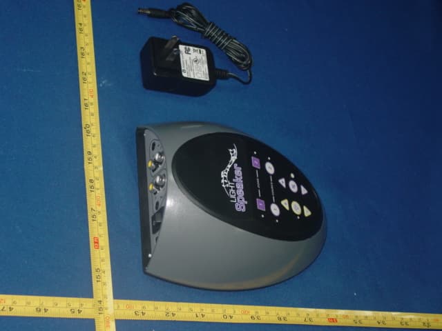
Click to zoom
Application Details
- Equipment Class
- DTS - Digital Transmission System
- Date of Grant
- Oct 26, 2010
- Application Purpose
- Original Equipment
- Date of Application
- Oct 25, 2010
- Equipment Note
- Transmitter
- Frequency Range
- 2412.00000000 - 2464.00000000
- Company
- Kadence Designs LLC
- Country
- American Samoa
Documents & Files
Document Text
Text extracted from the exhibit documents filed with the FCC. Open a document above to read the original.
Users Manual
Tech Support:1-800-KLIPSCH 1 OWNER’S MANUAL AND INSTALLATION INSTRUCTIONS State-of-the-art LIGHT & SOUND One complete system that installs in 30 minutes or less! 2 Tech Support:1-800-KLIPSCH The lightning flash with arrowhead symbol, within an equilateral triangle, is intended to alert the user to the presence of uninsulated “dangerous voltage” within the product’s enclosure that may be of sufficient magnitude to constitute a risk of electric shock to persons. Le symbole de l’éclair fléché dans un triangle équilatéral, a pour but d’avertir l’utilisateur de la présence non isolées d’une «tension dangereuse» dans le boîtier du produit que mai d’une magnitude suffisante pour constituer un risque d’électrocution pour les personnes. The exclamation point within an equilateral triangle is intended to alert the user to the presence of important operating and maintenance (servicing) instructions in the literature accompanying the appliance. Le point d’exclamation dans un triangle équilatéral sert à alerter l’utilisateur de la présence d’importantes exploitation et de maintenance (entretien) dans la documentation accompagnant l’appareil. Caution marking is located at the side of the apparatus. Attention marquage est situé sur le côté de l’appareil. CAUTION:Risk of Electrical Shock - Use in Dry Locations Only ATTENTION:Risque de Choc Électrique - Utiliser Seulement Dans des Endroits Secs CAUTION:To reduce the risk of electric shock, do not remove cover (or back). No user servicable parts – refer servicing to qualified service personnel only. ATTENTION:Pour réduire le risque de choc électrique, ne pas retirer le couvercle (ou l’arrière). Non utilisateur servicable parts - confier l’entretien de service qualifie seul le personnel. WARNING:To reduce the risk of fire or electric shock, do not expose this apparatus to rain or moisture. AVERTISSEMENT:Pour réduire le risque d’incendie ou de choc électrique, ne pas exposer cet appareil sous la pluie et l’humidité. Tech Support:1-800-KLIPSCH 3 IMPORTANT SAFETY INSTRUCTIONS 1. Read these instructions. Keep these instructions. Heed all Warnings. Follow all instructions. 2. Do not use this apparatus near water. The apparatus shall not be exposed to dripping or splashing and that no objects filled with liquids, such as vases, shall be placed on apparatus. 3. Clean only with a dry cloth. 4. Do not block any ventilation openings. Install in accordance with the manufacturer’s instructions. 5. Do not install near any heat sources such as radiators, heat registers, stoves, or other apparatus (including amplifiers) that produce heat. 6. The lamp holder is used as disconnect device. The lamp holder of apparatus should not be obstructed OR should be easily accessed during intended use. To completely disconnect the power input, the lamp holder of the apparatus shall be disconnected from the mains. 7. Only use attachments/accessories specified by the manufacturer. 8. Refer all servicing to qualified service personnel. Servicing is required when the apparatus has been damaged in any way, such as power-supply cord or plug is damaged, liquid has been spilled or objects have fallen into the apparatus, the apparatus has been exposed to rain or moisture, does not operate normally, or has been dropped. 9. Added weight of the device may cause instability of a free-standing portable lamp. Use only with portable table lamps in which the distance from the bottom of the base to the top of the lampholder does not exceed three (3) times minimum base width. Use only with portable table lamps which are provided with lamp shades” or the equivalent. 10. This device is not intended for use with emergency exit fixtures or emergency exit lights 11. NOT FOR USE WHERE EXPOSED TO THE WEATHER NE PAS EXPOSER AUX INTEMPÉRIES 12. NOT FOR USE IN TOTALLY ENCLOSED RECESSED LUMINAIRES NE PAS INSTALLER DANS DES LUMINAIRES ENCASTRÉS COMPLÈTEMENT FERMÉS 4 Tech Support:1-800-KLIPSCH Congratulations Thank you for choosing a LightSpeaker ® from Klipsch ® . You have chosen one of the most unique, patented, audio systems in the world. With proper installation and operation, you will enjoy years of trouble-free use. Klipsch ® sells numerous loudspeakers for use inside or outside your home. To see the complete Klipsch ® product assortment, visit us on the Internet at: www.Klipsch.com. Tech Support:1-800-KLIPSCH 5 Table of Contents System Overview....................................................................................6 What is in this box................................................................................8 Step 1 - Where will you install.........................................................9 Step 2 - Check your connector type...........................................9 Step 3 - Test fit your LightSpeaker ® ...........................................10 Step 4 - Removing the trim ring....................................................11 Step 5 - Installing the trim ring....................................................14 Step 6 - Adjusting the Simple Tabs TM .......................................15 Step 7 - Setting the zone and stereo switches...................16 Step 8 - Installing your LightSpeakers ® ...................................20 Step 9 - Pairing....................................................................................21 Step 10 - Plug in your sources......................................................23 Step 11 - Enjoy your LightSpeakers ® .........................................24 Operating the transmitter & remote control.......................25 Helpful hints...........................................................................................27 More about removing trim rings................................................30 Where to put the transmitter.....................................................33 Attaching the remote wall bracket.............................................33 Selecting LightSpeaker ® locations..............................…
Text truncated - open the document above for the full version.
Cover Letter(s)
AGENCY AUTHORIZATION LETTER FCC ID: XQ9T20200 Date: 5,August ,2010 To whom it may concern: We, the undersigned, hereby authorize NS Technology Co., Ltd. NS to act on our behalf, as our agent, in the following matters related to the FCC approval of our products: report submittal, related correspondence, the signing of all documents relating to these matters, and any other lawful activity necessary to obtain such certification. Any act carried out by NS within the scope of this authorization shall have the same effects as our own. This authorization shall expire 6 months form original date. If you have any Questions regarding the authorization, please don’t hesitate to contact us. Thank you. Sincerely, (親筆簽名)(英文) Sam M. Romano Jr. Design Consultant Kadence Designs LLC Tel: 1- 877-812-8346 Fax: 1- 877-812-8346 Website: www.lightspeaker.net E-Mail: [email protected]
Cover Letter(s)
Date: 5,August ,2010 Federal Communications Commission Authorization and Evaluation Division FCC ID: XQ9T20200 Confidentiality Request Pursuant to Sections 0.457 and 0.459 of the Commission’s Rules, the Applicant hereby requests confidential treatment of information accompanying this application as outlined below: 1. Block diagram 2. Schematics 3. Operation Description The above materials contain trade secrets and proprietary information not customarily released to the public. The public disclosure of these matters might to harmful to the applicant and provide unjustified benefits to its competitors. The applicant understands that pursuant to Rule 0.457, disclosure of this application and all accompanying documentation will not be made before the date of the grant for this application. Sincerely, (親筆簽名)(英文) Sam M. Romano Jr. Design Consultant Kadence Designs LLC Tel: 1- 877-812-8346 Fax: 1- 877-812-8346 Website: www.lightspeaker.net E-Mail: [email protected]
External Photos
Label Location
ID Label/Location Info
Label Location
Internal Photos
RX(908)Antenna TX/RX Antenna
RF Exposure Info
NS Technology Co., Ltd. Report No. NSE-F10085216 Page 1 of 4 IC ID:8684A-T20200 FCC ID:XQ9T20200 FCC and IC TEST REPORT for KADENCE DESIGNS LLC Transmitter Model Number: T 2.2 Prepared for : KADENCE DESIGNS LLC Address : P.O.Box 2359,Thompson Falls,MT 59873 Prepared By : NS Technology Co., Ltd. Address : Chenwu Industrial Zone, Houjie Town, Dongguan City, Guangdong, China Tel: +86-769-85935656 Fax: +86-769-85991080 Report Number : NSE-F10085216 Date of Test : Jul. 30, 2010 Date of Report : Aug. 15, 2010 Te s t L a b Cert 2951.01 NS Technology Co., Ltd. Report No. NSE-F10085216 Page 2 of 4 IC ID:8684A-T20200 FCC ID:XQ9T20200 NS Technology Co., Ltd. Applicant: Address: KADENCE DESIGNS LLC P.O.Box 2359,Thompson Falls,MT 59873 Manufacturer: Address: Celewave Electronics(shenzhen) Co.,Ltd No 1-2 building,No 2 Industry District, Shang Heng lang Huaxing Road, Dalang Street,Baoan District, Shenzhen City,China E.U.T: Transmitter Model Number: T 2.2 Report Number: NSE-F10085216 Tra de Name: Lightspeaker TM Operating Frequency: 2412~2464MHz Date of Receipt: Jul.17, 2010 Date of Test: Aug. 9, 2010 Test Specification: RSS-210 Issue 7 2007 47 CFR FCC Part 2 Subpart J, section 2.1091 Test Result: The equipment under test was found to be compliance with the requirements of the standards applied. Issue Date: Aug. 15, 2010 Tested by: Reviewed by: Approved by: Jade/ Engineer Iceman Hu / Supervisor Steven Lee / Manager Other Aspects: None. Abbreviations: OK/P=passed fail/F=failed n.a/N=not applicable E.U.T=equipment under tested This test report is based on a single evaluation of one sample of above mentioned products ,It is not permitted to be duplicated in extracts without written approval of NS Technology Co., Ltd. NS Technology Co., Ltd. Report No. NSE-F10085216 Page 3 of 4 IC ID:8684A-T20200 FCC ID:XQ9T20200 Maximum Permissible Exposure 1 Applicable Standard Systems operating under the provisions of this section shall be operated in a manner that ensures that the public is not exposed to radio frequency energy level in excess limit for maximum permissible exposure. In accordance with 47 CFR FCC Part 2 Subpart J, section 2.1091 this device has been defined as a mobile device whereby a distance of 0.2m normally can be maintained between the user and the device. (a) Limits for Occupational / Controlled Exposure Frequency Range (MHz) Electric Field Strength (E) (V/m) Magnetic Field Strength (H) (A/m) Power Density(S) (mW/cm 2 ) Averaging Times ︱E︱ 2 ,︱H︱ 2 or S (minutes) 0.3-3.0 614 1.63 (100)* 6 3.0-30 1842/f 4.89/f (900/f)* 6 30-300 61.4 0.163 1.0 6 300-1500 F/300 6 1500-100000 5 6 (b) Limits for General Population / Uncontrolled Exposure Frequency Range (MHz) Electric Field Strength (E) (V/m) Magnetic Field Strength (H) (A/m) Power Density(S) (mW/cm2) Averaging Times ︱E︱ 2 ,︱H︱ 2 or S (minutes) 0.3-1.34 614 1.63 (100)* 30 1.34-30 824/f 2.19/f (180/f)* 30 30-300 27.5 0.073 0.2 30 300-1500 F/1500 30 1500-100000 1.0 30 Note: f=frequency in MHz; *Plane-wave equivalent power density 2 MPE Calculation Method E (V/m) = (30*P*G) 0.5 /d Power Density: Pd (W/m 2 ) = E 2 /377 E = Electric Field (V/m) P = Peak RF output Power (W) G = EUT Antenna numeric gain (numeric) d = Separation distance between radiator and human body (m) The formula can be changed to Pd = (30*P*G) / (377*d 2 ) From the peak EUT RF output power, the minimum mobile separation distance, d=0.2m, as well as the gain of the used antenna, the RF power density can be obtained. NS Technology Co., Ltd. Report No. NSE-F10085216 Page 4 of 4 IC ID:8684A-T20200 FCC ID:XQ9T20200 3 Calculated Result and Limit Mode CH Output power (dBm) Output power (mW) Antenna Gain (dBi) MPE estimation result (mW/cm²) at 20cm Limit of MPE Estimation (mW/cm²) Test result CH1:2412MHz 15.42 34.83 1.1 0.0028 1 Compiles CH2:2438MHz 15.09 32.28 1.1 0.0026 1 Compiles Antenna1 CH3:2464MHz 15.11 32.43 1.1 0.0026 1 Compiles CH1:2412MHz 15.34 34.20 1.1 0.0027 1 Compiles CH2:2438MHz 15.13 32.58 1.1 0.0026 1 Compiles Antenna2 CH3:2464MHz 14.97 31.41 1.1 0.0025 1 Compiles
Test Report
FCC ID: XQ9T20200 IC ID: 8684A-T20200 NS Technology Co., Ltd. Report No. NSE-F10085215 Page 1 of 85 FCC and IC TEST REPORT for Kadence Designs LLC Transmitter Model Number: T 2.2 Prepared for : Kadence Designs LLC Address : P.O.Box 2359,Thompson Falls,MT 59873 Prepared By : NS Technology Co., Ltd. Address : Chenwu Industrial Zone, Houjie Town, Dongguan City, Guangdong, China Tel: +86-769-85935656 Fax: +86-769-85991080 Report Number : NSE-F10085215 Date of Test : Jul. 25~Aug. 10, 2010 Date of Report : Aug. 9, 2010 Test Lab Cert 2951.01 FCC ID: XQ9T20200 IC ID: 8684A-T20200 NS Technology Co., Ltd. Report No. NSE-F10085215 Page 2 of 85 TABLE OF CONTENTS Test Report Declaration Page 1. GENERAL PRODUCT INFORMATION ......................................................................... 4 1.1. Product Function ......................................................................................................................... 4 1.2. Description of Device (EUT) ...................................................................................................... 4 1.3. Difference between Model Numbers .......................................................................................... 4 1.4. Independent Operation Modes ....................................................................................................4 2. TEST SITES.......................................................................................................................... 5 2.1. Test Facilities .............................................................................................................................. 5 2.2. List of Test and Measurement Instruments ................................................................................. 6 3. TEST SET-UP AND OPERATION MODES .................................................................... 7 3.1. Principle of Configuration Selection...........................................................................................7 3.2. Block Diagram of Test Set-up..................................................................................................... 7 3.3. Test Operation Mode and Test Software..................................................................................... 7 3.4. Special Accessories and Auxiliary Equipment ........................................................................... 7 3.5. Countermeasures to Achieve EMC Compliance......................................................................... 7 4. TEST SUMMARY................................................................................................................ 8 5. EMISSION TEST RESULTS.............................................................................................. 9 5.1. Conducted Emission at The Mains Terminals Test..................................................................... 9 5.2. Radiated Emission..................................................................................................................... 16 5.3. Conducted emission test data ....................................................................................................58 5.4. 6dB Bandwidth ......................................................................................................................... 61 5.5. 99% Bandwidth ......................................................................................................................... 63 5.6. Power Spectral Density Test .....................................................................................................65 5.7. Output Power Test..................................................................................................................... 67 5.8. Band Edge ................................................................................................................................. 68 5.9. ANTENNA REQUIREMENT ................................................................................................. 85 FCC ID: XQ9T20200 IC ID: 8684A-T20200 NS Technology Co., Ltd. Report No. NSE-F10085215 Page 3 of 85 NS Technology Co., Ltd. Applicant: Address: Kadence Designs LLC P.O.Box 2359,Thompson Falls,MT 59873 Manufacturer: Address: Celewave Electronics(shenzhen) Co.,Ltd No 1-2 building,No 2 Industry District, Shang Heng lang Huaxing Road, Dalang Street,Baoan District, Shenzhen City,China E.U.T: Transmitter Model Number: T 2.2 Trade Name: Lightspeaker TM Operating Frequency: 2412~2464MHz Date of Receipt: Jul.17, 2010 Date of Test: Jul. 25~Aug. 10, 2010 Test Specification: FCC Part15C :Oct.1, 2009 ANSI C63.4:2003 RSS-210,Issue 7 June 2007 RSS-GEN, Issue 2 June 2007 Test Result: The equipment under test was found to be compliance with the requirements of the standards applied. Issue Date: Aug. 15, 2010 Tested by: Reviewed by: Approved by: Jade/ Engineer Iceman Hu / Supervisor Steven Lee / Manager Other Aspects: None. Abbreviations: OK/P=passed fail/F=failed n.a/N=not applicable E.U.T=equipment under tested This test report is based on a single evaluation of one sample of above mentioned products ,It is not permitted to be duplicated in extracts without written approval of NS Technology Co., Ltd. FCC ID: XQ9T20200 IC ID: 8684A-T20200 NS Technology Co., Ltd. Report No. NSE-F10085215 Page 4 of 85 1. GENERAL PRODUCT INFORMATION 1.1. Product Function Details please refer to Technical Construction Form and User Manual. 1.2. Description of Device (EUT) E.U.T. : Transmitter Model No. : T 2.2 Operating Frequency : 2412~2464MHz Number of Channels : 3 Channels Type of Modulation : DSSS(QPSK) Antenna Type : Integral Antenna Gain : 1.1dBi System Input Voltage : DC 9V from adapter input AC 120V/60Hz Temperature Range(Operating) : 0 ~+ 40°C Adapter : M/N:YS01-090065U I/P:100-240V~50/60Hz 0.32A MAX O/P:9V 0~650mA DC Line:Unshielded,Undetachable ,1.5m 1.3. Difference between Model Numbers 1.4. Independent Operation Modes The basic operation modes are: 1.4.1 TX CH1 ANT1 (2412MHz)…
Text truncated - open the document above for the full version.
Test Setup Photos
Set-up for conducted emission at the mains terminals test Set-up for radiated emission test (30MHz~1GHz) Set-up for radiated emission test(Above 1GHz) Set-up for 6dB and 99% banwith test Set-up for output power test
Contact Information
Applicant
Sam Romano
Technical Contact
NS Technology Co., Ltd.Iceman Hu
[email protected]+86-769-85935656
Chenwu Industrial Zone, Houjie Town · Dongguan · China
Non-Technical Contact
NS Technology Co., Ltd.Iceman Hu
[email protected]+86-769-85935656
Test Firm
Bureau Veritas Shenzhen Co., Ltd. Dongguan BranchAlec Hu
Technical Specifications
| # | Rule Parts | Frequency Range | Power Output |
|---|---|---|---|
| 1 | 15C | 2.41 GHz - 2.46 GHz | 34.83 mW |
Other Applications from Kadence Designs LLC

XQ9W60200
Sep 12, 2010Subwoofer W6.2.0
Equipment Class
DTS - Digital Transmission System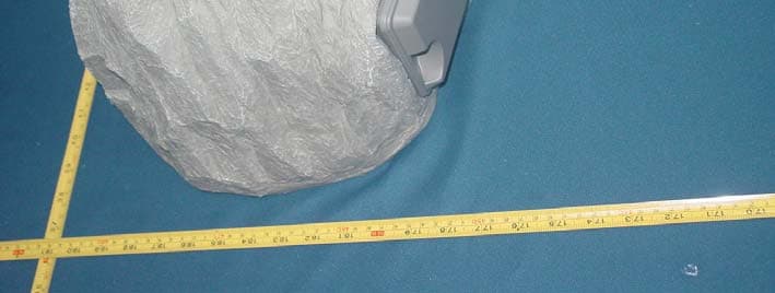
XQ9R50200
Jun 20, 2010AudioRock 5
Equipment Class
DTS - Digital Transmission System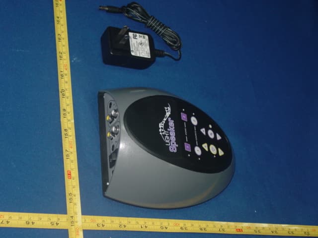
XQ9T2020
Dec 05, 2009Transmitter
Equipment Class
DXX - Part 15 Low Power Communication Device Transmitter