XQC-1042R01Wall Mounted Sensor
Ecolink Intelligent Technology, Inc.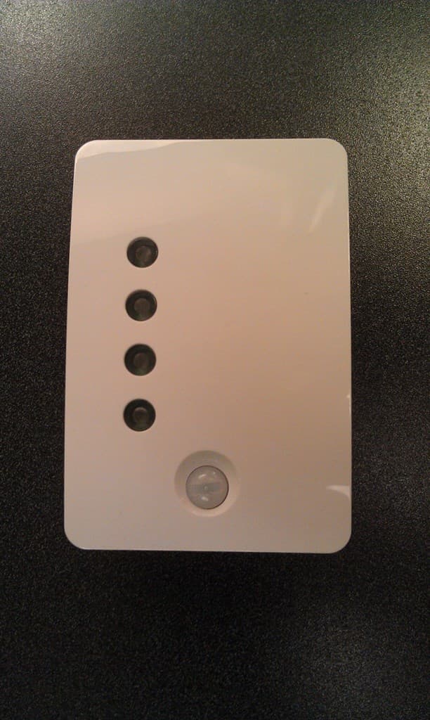
Click to zoom
Application Details
- Equipment Class
- DSR - Part 15 Remote Control/Security Device Transceiver
- Date of Grant
- Jan 12, 2014
- Application Purpose
- Original Equipment
- Date of Application
- Jan 12, 2014
- Equipment Note
- Wall Mounted Sensor
- Frequency Range
- 433.92000000 - 433.92000000
- Country
- United States
Documents & Files
Document Text
Text extracted from the exhibit documents filed with the FCC. Open a document above to read the original.
Users Manual
Ecolink Status Indicator Model#: STAT433 Status Module Installation Manual and User Guide Ecolink Bridge (Model#: BOOM433) - this is the main control units for this system. It must be located in the same room but not more than 50ft of your Zwave gateway. Status Module (Model#: STAT433) - this device provides the current status of the sensor installed on your doors and windows. This should be located at your main entry/exit door (to check status as your leave) or by your bedroom (to check status before you go to bed at night) Door/Window sensor (Model#: DOOR433) - these are the sensors that you will mount on your doors and windows. It will transmit back to the unit if the door/window is opened or closed. Setup The suggested process for configuring your system is as follows. 1. Power up the bridge 2. Enroll your door/window sensors 3. Enroll the status module 4. Install your door/window sensors 5. Test your system 6. Mount your status module 7. Include your Insynctive network into a Zwave gateway (optional) Power up the bridge Your Ecolink Bridge comes ready to plug into any standard electrical outlet. However there are a number of jumpers located in the battery compartment that control the door chime feature. You may want to adjust this prior to plugging it in as they are not accessible after you do so. The jumper options are as follows: Volume Chime J1 J2 J3 J4 Operation off off X X Volume controlled by Z-wave GUI off on X X Low volume on off X X Med volume on on X X High volume (default) X X off off No chime X X off on Chime when door or window is opened X X on off Chime when door or window is unlocked X X on on Chime when door or window is opened or unlocked (default) The first time you plug in your bridge, the light will turn green, then start flashing blue. Enroll Door/window sensors Unpack your sensors, including the magnet. Slide the top cover to disengage it from the bottom. Remove the top cover to reveal the battery. Remove the plastic tab that is installed underneath the battery. Ensure the battery is firmly in place. At this point you can decide to replace the white cover or switch to the brown cover. The brown cover, when installed, will cover the bottom piece so only brown is visible after installation. After you power up the sensor, you have approximately 2 minutes to enroll the sensor into the bridge. If more than 2 minutes has elapsed, just remove the battery and reinstall to get another 2 minute window. To start the learn process, you must press the learn button on the bridge. This is the bottom button located on the side of the bridge When you press this, the bridge will start to flash orange. To trigger a learn command from the sensor, touch the magnet to the sensor three times within 2 seconds. If successful the bridge will flash green and beep once for 2sec. At this point it is recommended to record the sequence in which sensors were enrolled and where this sensor will be mounted. This will prove useful when including your system into a Zwave network. Repeat this step until all your sensors have been enrolled into the bridge. When you are done, press the learn button again to exit this mode. As you move the magnet back and forth within range of the sensor bridge will beep. This is the chime feature and is useful to determine when someone opens a door or window within the home. It also confirms the sensor was properly enrolled. Enroll Status Module Unpack the status module and insert the 2 AA batteries. Do not put the battery cover back on. Press the learn button on the bridge to activate the learn mode. The bridge will start to flash orange. Press the button on the status module that is located underneath the battery compartment If successfully enrolled the status module will beep. Press the learn button on the bridge to exit this mode. At this point you can replace the battery cover of the status module. At this point, one of the bottom LEDs (open or closed) may be illuminated. This is showing the status of the sensor you have enrolled but have not yet installed. Installing and testing your sensors Your sensors come in two parts, the actual transmitter and the magnet. You must choose a location on the door or window such that when installed the maximum distance between the sensor and the magnet is 0.5 inches. It is preferred (but not mandatory) that the sensor be mounted on the frame and the magnet on the door. Double sided tape is included with your sensor to mount the devices. Ensure the surface is clean and dry. Apply the tape to the sensor then press firmly into the designated location on the door or window. Hold for 10 seconds. Repeat for the magnet. Once your sensor is correctly installed, open and close the door or window. As you open you should hear the bridge beep. Note the bridge will not beep when you close the door. Repeat these steps until all your sensors are installed. Using the status module to test If you are in a part of the home where you cannot hear the bridge, you can use the status module to help you test the devices you are installing. To do so you must make sure all the devices that are enrolled in the system are in the closed state. So if already mounted the door and window must be closed, if not mounted the magnets must be touching the sensor. You can confirm this as the status module will illuminate the green (closed) LED. Then simply bring the status module with you as you install your device, when you open and close the door you have installed the sensor on, the status module will illuminate the open (Red) or closed (green) light accordingly. Mount the status module Once the installation is complete, mount the wall bracket of the status module to the desired location and install the status module. The status module is designed to be off, when motion within 2-3 ft is detected directly in front of it, it will turn on, and request status from the bridge. After a few minutes of not detecting motion it will turn off. If the open LED (red) flas…
Text truncated - open the document above for the full version.
Cover Letter(s)
Ecolink Intelligent Technology, Inc. Page 1 of 2 2055 Corte Del Nogal Carlsbad, CA 92011 November 18, 2013 UL LLC Certification Division 47173 Benicia Street Fremont, CA 94538, USA To whom it may concern: I, the undersigned, hereby authorize UL LLC to act on our behalf in all manners relating to application for equipment authorization, including signing of all documents relating to these matters. Any and all acts carried out by UL LLC on our behalf shall have the same effect as acts of our own. I, the undersigned, hereby certify that we are not subject to a denial of federal benefits, that includes FCC benefits, pursuant to Section 5301 of the Anti-Drug Abuse Act of 1988, 21 U.S.C. 853(a). In authorizing UL LLC as our agent, we still recognize that we are responsible to: a) comply with the relevant provisions of the certification program; b) make all necessary arrangements for the conduct of the evaluation, including provision for examining documentation and access to all areas, records (including internal audit reports) and personnel for the purposes of evaluation (e.g. testing, inspection, assessment, surveillance, reassessment) and resolution of complaints; c) make claims regarding certification only in respect of the scope for which certification has been granted; d) do not use our product certification in such a manner as to bring the Certification Division into disrepute and not make any statement regarding our product certification which the Certification Division may consider misleading or unauthorized; e) upon suspension or cancellation of certification, discontinue use of all advertising matter that contains any reference thereto and return any certification documents as required by the Certification Division; f) use certification only to indicate the products are certified as being in conformity with specified standards; g) endeavor to ensure that no certificate or report nor any part thereof is used in a misleading manner;
ID Label/Location Info
This device complies with Part 15 of the FCC Rules. Operation is subject to the following two conditions: (1) this device may not cause harmful interference, and (2) this device must accept any interference received, including interference that may cause undesired operation. Model No. STAT433 FCC ID: XQC-1042R01 IC:9863B-1042R01 FCC Identification Label Location
Test Report
NVLAP Lab 100414-0 FCC 47 CFR PART 15 SUBPART C INDUSTRY CANADA RSS-210 ISSUE 8 CERTIFICATION TEST REPORT FOR Security Motion Sensor MODEL NUMBER: STAT433 FCC ID: XQC-1042R01 IC: 9863B-1042R01 REPORT NUMBER: 13U16490 Revision A ORDER NUMBER: 10117140A ISSUE DATE: JANUARY 7, 2014 Prepared for ECOLINK INTELLIGENT TECHNOLOGY 2055 CORTE DEL NOGAL CARLSBAD, CA 92011 Prepared by UL LLC 333 PFINGSTEN RD NORTHBROOK, IL 60062 TEL: (847) 272-8800 REPORT NO: 13U16490-A DATE: January 7, 2014 FCC ID: XQC-1042R01 IC:9863B-1042R01 Page 2 of 29 UL LLC FORM NO: CCSUP4701I 333 Pfingsten Rd. Northbrook, Il 60062, USA TEL: (847)272-8800 This report shall not be reproduced except in full, without the written approval of UL Verification Services Inc.. Revision History Rev. Issue Date Revisions Revised By -- 12/10/13 Initial Issue D. Cieplik A 1/7/14 Page 18, test limits for 130-174 and 260-470MHz now revised in the 15.205 table. D. Cieplik REPORT NO: 13U16490-A DATE: January 7, 2014 FCC ID: XQC-1042R01 IC:9863B-1042R01 Page 3 of 29 UL LLC FORM NO: CCSUP4701I 333 Pfingsten Rd. Northbrook, Il 60062, USA TEL: (847)272-8800 This report shall not be reproduced except in full, without the written approval of UL Verification Services Inc.. TABLE OF CONTENTS 1. ATTESTATION OF TEST RESULTS ................................................................................. 4 2. EQUIPMENT UNDER TEST ............................................................................................... 5 3. TEST METHODOLOGY ..................................................................................................... 5 4. FACILITIES AND ACCREDITATION ................................................................................. 5 5. CALIBRATION AND UNCERTAINTY ................................................................................ 6 5.1. MEASURING INSTRUMENT CALIBRATION .............................................................. 6 5.2. SAMPLE CALCULATION ............................................................................................ 6 5.3. MEASUREMENT UNCERTAINTY ............................................................................... 6 5.1. DESCRIPTION OF TEST SETUP ................................................................................ 7 5.2. TEST AND MEASUREMENT EQUIPMENT................................................................. 8 6. DUTY CYCLE ..................................................................................................................... 9 7. 20 dB AND 99% BW .........................................................................................................13 8. TRANSMISSION TIME ......................................................................................................17 9. RADIATED EMISSION TEST RESULTS...........................................................................18 10. TX RADIATED SPURIOUS EMISSION ..........................................................................18 1. SETUP PHOTOS ...............................................................................................................24 REPORT NO: 13U16490-A DATE: January 7, 2014 FCC ID: XQC-1042R01 IC:9863B-1042R01 Page 4 of 29 UL LLC FORM NO: CCSUP4701I 333 Pfingsten Rd. Northbrook, Il 60062, USA TEL: (847)272-8800 This report shall not be reproduced except in full, without the written approval of UL Verification Services Inc.. 1. ATTESTATION OF TEST RESULTS COMPANY NAME: Ecolink 2055 Corte Del Nogal Carlsbad, CA 92011 EUT DESCRIPTION: Security Motion Sensor MODEL: STAT433 DATE TESTED: December 2-9, 2013 APPLICABLE STANDARDS STANDARD TEST RESULTS FCC PART 15 SUBPART C Pass INDUSTRY CANADA RSS-210 Issue 8, Annex 1 Pass INDUSTRY CANADA RSS-GEN Issue 3 Pass UL Verification Services Inc tested the above equipment in accordance with the requirements set forth in the above standards. All indications of Pass/Fail in this report are opinions expressed by UL Verification Services Inc. based on interpretations and/or observations of test results. Measurement Uncertainties were not taken into account and are published for informational purposes only. The test results show that the equipment tested is capable of demonstrating compliance with the requirements as documented in this report. Note: The results documented in this report apply only to the tested sample, under the conditions and modes of operation as described herein. This document may not be altered or revised in any way unless done so by UL Verification Services Inc. and all revisions are duly noted in the revisions section. Any alteration of this document not carried out by UL Verification Services Inc will constitute fraud and shall nullify the document. This report must not be used by the client to claim product certification, approval, or endorsement by NVLAP, NIST, any agency of the Federal Government, or any agency of any government. Approved & Released For UL Verification Services Inc By: Tested By: Bart Mucha Dan Cieplik WiSE Staff Engineer WiSE Project Lead UL Verification Services Inc. UL Verification Services Inc. REPORT NO: 13U16490-A DATE: January 7, 2014 FCC ID: XQC-1042R01 IC:9863B-1042R01 Page 5 of 29 UL LLC FORM NO: CCSUP4701I 333 Pfingsten Rd. Northbrook, Il 60062, USA TEL: (847)272-8800 This report shall not be reproduced except in full, without the written approval of UL Verification Services Inc.. 2. EQUIPMENT UNDER TEST 2.1. DESCRIPTION OF EUT The EUT is a Transmitter intended for Security use. It is a wall-mounted fixture with indication LEDs. The EUT uses 2 AA batteries. 2.2. DESCRIPTION OF AVAILABLE ANTENNAS The radio utilizes a helical monopole soldered to the PCB antenna, with a maximum gain of -5dBi. 2.3. SOFTWARE AND FIRMWARE The firmware installed in the EUT during testing was ESW1042-01-A10. 2.4. WORST-CASE CONFIGURATION AND MODE The worst-case Orientation is determined as the X-axis with preliminary testing. 2.5. MODIFICATIONS No modifications were made during testing.…
Text truncated - open the document above for the full version.
Test Setup Photos
REPORT NO: 13U16490 DATE: December 10, 2013 FCC ID: XQC-1042R01 IC:9863B-1042R01 Page 24 of 29 UL LLC FORM NO: CCSUP4701I 333 Pfingsten Rd. Northbrook, Il 60062, USA TEL: (847)272-8800 This report shall not be reproduced except in full, without the written approval of UL Verification Services Inc.. 1. SETUP PHOTOS RADIATED EMISSION CONFIGURATION – X ORIENTATION REPORT NO: 13U16490 DATE: December 10, 2013 FCC ID: XQC-1042R01 IC:9863B-1042R01 Page 25 of 29 UL LLC FORM NO: CCSUP4701I 333 Pfingsten Rd. Northbrook, Il 60062, USA TEL: (847)272-8800 This report shall not be reproduced except in full, without the written approval of UL Verification Services Inc.. RADIATED EMISSION CONFIGURATION – Y ORIENTATION REPORT NO: 13U16490 DATE: December 10, 2013 FCC ID: XQC-1042R01 IC:9863B-1042R01 Page 26 of 29 UL LLC FORM NO: CCSUP4701I 333 Pfingsten Rd. Northbrook, Il 60062, USA TEL: (847)272-8800 This report shall not be reproduced except in full, without the written approval of UL Verification Services Inc.. RADIATED EMISSION CONFIGURATION – Z ORIENTATION REPORT NO: 13U16490 DATE: December 10, 2013 FCC ID: XQC-1042R01 IC:9863B-1042R01 Page 27 of 29 UL LLC FORM NO: CCSUP4701I 333 Pfingsten Rd. Northbrook, Il 60062, USA TEL: (847)272-8800 This report shall not be reproduced except in full, without the written approval of UL Verification Services Inc.. RADIATED EMISSION BELOW 30 MHz REPORT NO: 13U16490 DATE: December 10, 2013 FCC ID: XQC-1042R01 IC:9863B-1042R01 Page 28 of 29 UL LLC FORM NO: CCSUP4701I 333 Pfingsten Rd. Northbrook, Il 60062, USA TEL: (847)272-8800 This report shall not be reproduced except in full, without the written approval of UL Verification Services Inc.. RADIATED EMISSION ABOVE 30 MHz REPORT NO: 13U16490 DATE: December 10, 2013 FCC ID: XQC-1042R01 IC:9863B-1042R01 Page 29 of 29 UL LLC FORM NO: CCSUP4701I 333 Pfingsten Rd. Northbrook, Il 60062, USA TEL: (847)272-8800 This report shall not be reproduced except in full, without the written approval of UL Verification Services Inc.. Near Field Measurements END OF REPORT
Contact Information
Applicant
Jay Stone
Test Firm
UL LLCRick Titus
Technical Specifications
| # | Rule Parts | Frequency Range | Power Output |
|---|---|---|---|
| 1 | 15.231 | 433.92 MHz - 433.92 MHz | - |
Other Applications from Ecolink Intelligent Technology, Inc.

XQC-WST132
Feb 07, 2024Wearable Action Button
Equipment Class
DSC - Part 15 Security/Remote Control Transmitter
XQC-WST621
May 01, 2023Flood and Freeze Sensor
Equipment Class
DSC - Part 15 Security/Remote Control Transmitter
XQC-WST740
Jul 04, 2022Motion Detector
Equipment Class
DSC - Part 15 Security/Remote Control Transmitter
XQC-WST742
Feb 17, 2021Motion Detector
Equipment Class
DSR - Part 15 Remote Control/Security Device Transceiver
XQC-CS602
Feb 17, 2021Audio Detector
Equipment Class
DSC - Part 15 Security/Remote Control Transmitter