XR2WIZ63OWIWireless LAN Module
WIZNET Co., LTD.Application Details
- Equipment Class
- DTS - Digital Transmission System
- Date of Grant
- Sep 21, 2014
- Application Purpose
- Original Equipment
- Date of Application
- Sep 21, 2014
- Equipment Note
- Wireless LAN Module
- Frequency Range
- 2422.00000000 - 2452.00000000
- Company
- WIZNET Co., LTD.
- Country
- South Korea
Documents & Files
Document Text
Text extracted from the exhibit documents filed with the FCC. Open a document above to read the original.
Users Manual
© Copyright 2012 WIZnet Co., Ltd. All rights reserved. 1 WizFi630 User Manual (Version 1.1) © 2012 WIZnet Co., Ltd. All Rights Reserved. For more information, please visit our website at http://www.wiznet.co.kr © Copyright 2012 WIZnet Co., Ltd. All rights reserved. 2 Certification Information CE for Class B ITE INFORMATION TO THE USER Hereby, WIZnet. Declares that this WizFi630 is in compliance with the essential requirements and other relevant provisions of directive 1999/5/EC and other relevant provisions of directive 1999/5/EC. WARNING: This is a class B product. In a domestic environment this product may cause radio interference in which case the user may be required to take adequate measures FCC for Class B ITE INFORMATION TO THE USER This equipment has been tested and found to comply with the limits for a Class B digital device, pursuant to part 15 of the FCC Rules. These limits are designed to provide reasonable protection against harmful interference in a residential installation. This equipment generates, uses and can radiate radio frequency energy and, if not installed and used in accordance with the instructions, may cause harmful interference to radio communications. However, there is no Guarantee that interference will not occur in a particular installation. If this equipment does cause harmful interference to radio or television reception, which can be determined by turning the equipment off and on, the user is encouraged to try to correct the interference by one more of the following measures : - Reorient or relocate the receiving antenna. - Increase the separation between the equipment and receiver. - Connect the equipment into an outlet on a circuit different from that to which the receiver is connected. - Consult the dealer or an experienced radio/TV technician for help. WARNING: This equipment may generate or use radio frequency energy. Changes or modifications to this equipment may cause harmful interference unless the modifications are expressly approved in the instruction manual. The user could lose the authority to operate this equipment if an unauthorized change or modification is made © Copyright 2012 WIZnet Co., Ltd. All rights reserved. 3 Document Revision History Date Revision Changes 2012-07-02 1.0 Release 2012-07-17 1.1 Change WizFi630’s picture at P10 Modify error sentence - P6, P18,P19 : WIZ630wi Æ WizFi630 - P24 : DNS server Æ DNS server address - P38 : WDS Æ WPS © Copyright 2012 WIZnet Co., Ltd. All rights reserved. 4 <Contents> 1. Introduction .................................................................................. 6 1.1. Features .............................................................................................................................................. 7 1.2. Wireless Specifications ................................................................................................................. 8 1.3. Hardware Specifications ............................................................................................................... 9 1.4. Software Specifications ............................................................................................................. 10 1.4.1. Contents ............................................................................................................................................ 10 1.5. Block Diagram ............................................................................................................................... 11 2. Operation Mode and Description of Menu ......................... 12 2.1. Operation Mode .......................................................................................................................... 12 2.1.1. Access Point .................................................................................................................................. 12 2.1.2. Gateway ........................................................................................................................................... 13 2.1.3. Client (Station) .............................................................................................................................. 13 2.1.4. AP-Client Mode ........................................................................................................................... 14 2.1.5. Ad-hoc Mode ............................................................................................................................... 14 2.2. Menu List by Operation Mode .............................................................................................. 15 2.2.1. Access Point (Bridge) Mode .................................................................................................. 15 2.2.2. Gateway (Router) Mode ........................................................................................................... 16 2.2.3. Client (Station) Mode ................................................................................................................ 17 2.2.4. AP-Client Mode ........................................................................................................................... 18 2.2.5. Ad-hoc Mode ............................................................................................................................... 20 2.3. Internet Setting ............................................................................................................................. 22 2.3.1. Internet connection setting ................................................................................................... 22 2.3.2. Local network setting ............................................................................................................... 24 2.3.3. DHCP Client Information ......................................................................................................... 25 2.3.4. VPN setting ....................................................................…
Text truncated - open the document above for the full version.
Cover Letter(s)
F W 4 S R D P co (X ☑ ☑ ☑ ☑ A c p s < a < < < K FCC, Reque WIZNET Co., F Humax Vil Subject: Req Reference nu Dear FCC TC Persuant to onfidential tr XR2WIZ63O ☑ Bill(s) of M ☑ Block Diag ☑ Operationa ☑ Schematic Above materia ustomarily be ublication or ubstantial co WIZNET Co nd all accom Date> Aug, City> Seong Name and s Kim Byung-ko est for non , LTD. lage, 11-4, S quest for conf umber: CB, 47 CFR Se reatment of t OWI) Material grams al Descriptio c Diagrams als contain s e quarded fr r any portion ompetitive ha o., LTD.> un mpanying doc 27, 2014 gnam-si, Gye signature of a ook / Senior -disclosure Sunae-dong, fidentiality FC ection 0.459 the following on secrets, prop om competit of this comp arm and prov nderstands t cumentation eonggi-do applicant> Engineer e Bundang-gu CC ID: XR2W 9(a) & (b), materials su rietary and te tors under 47 pany confiden vide unjustifie hat pursuant will not be m u, Seongnam WIZ63OWI < WIZNET ubmitted in s echnical info 7 CFR, sectio ntial materia ed benefits fo t to 47 CFR made before m-si, Gyeong Co.,LTD.> support of FC ormation, wh on 0.457(d)(2 l to other par or competito R section 0.4 the date of th FC Dat gi-do, South hereby requ CC certificatio ich would 2). Disclosur rties could ca rs. 57(d)(1)(ii) d he grant. CC ID : XR2W te: Aug, 27 h Korea uests non-d on applicatio re or ause disclosure of WIZ63OWI Page 1 / 1 7, 2014 isclosure an on for FCC ID f the applica nd D: nt
Cover Letter(s)
Applicant/Grantee WIZNET Co.,LTD. FCC ID: XR2WIZ63O WI Section 15.212 Modular Transmitters Request for Modular Approval Request for Limited Modular Approval Requirements EUT Conditions Comply (Y/N) Single Modular Approval Requirements 1 The radio elements of the modular transmitter must have their own shielding. The physical crystal and tuning capacitors may be located external to the shielded radio elements. Refer to external photos. Shield is over the radio circuit module. Y 2 The modular transmitter must have buffered modulation/data inputs (if such inputs are provided) to ensure that the module will comply with Part 15 requirements under conditions of excessive data rates or over- modulation. All inputs to the modules are buffered through logic or microprocessor inputs. Refer to Schematics. Y 3 The modular transmitter must have its own power supply regulation. Internal 3.3V power regulator. Refer to schematics. Y 4 The modular transmitter must comply with the antenna and transmission system requirements of Sections 15.203, 15.204(b) and 15.204(c). The antenna must either be permanently attached or employ a “unique” antenna coupler (at all connections between the module and the antenna, including the cable). The “professional installation” provision of Section 15.203 is not applicable to modules but can apply to limited modular approvals under paragraph (b) of this section. Module contains a connector. The module will go inside final product where the antenna(s) will be integral to the end product, which can be considered permanently attached. Y 5 The modular transmitter must be tested in a stand-alone configuration, i.e., the module must not be inside another device during testing for compliance with Part 15 requirements. Unless the transmitter module will be battery powered, it must comply with the AC line conducted requirements found in Section 15.207. AC or DC power lines and data input/output lines connected to the module must not contain ferrites, unless they will be marketed with the module (see Section 15.27(a)). The length of these lines shall be the length typical of actual use or, if that length is unknown, at least 10 centimeters to insure that there is no coupling between the case of the module and supporting equipment. Any accessories, peripherals, or support equipment connected to the module during testing shall be unmodified and commercially available (see Section 15.31(i)). Module was tested outside. Refer to test setup photos in test report. Y 6 The modular transmitter must be equipped with either a permanently affixed label or must be capable of electronically displaying its FCC identification number. (A) If using a permanently affixed label, the modular transmitter must be labeled with its own FCC identification number, and, if the FCC identification number is not visible when the module is installed inside another device, then Refer to label provided. Y the outside of the device into which the module is installed must also display a label referring to the enclosed module. This exterior label can use wording such as the following: “Contains Transmitter Module FCC ID: XYZMODEL1” or “Contains FCC ID: XYZMODEL1.” Any similar wording that expresses the same meaning may be used. The Grantee may either provide such a label, an example of which must be included in the application for equipment authorization, or, must provide adequate instructions along with the module which explain this requirement. In the latter case, a copy of these instructions must be included in the application for equipment authorization. (B) If the modular transmitter uses an electronic display of the FCC identification number, the information must be readily accessible and visible on the modular transmitter or on the device in which it is installed. If the module is installed inside another device, then the outside of the device into which the module is installed must display a label referring to the enclosed module. This exterior label can use wording such as the following: “Contains FCC certified transmitter module(s).” Any similar wording that expresses the same meaning may be used. The user manual must include instructions on how to access the electronic display. A copy of these instructions must be included in the application for equipment authorization. 7 The modular transmitter must comply with any specific rules or operating requirements that ordinarily apply to a complete transmitter and the manufacturer must provide adequate instructions along with the module to explain any such requirements. A copy of these instructions must be included in the application for equipment authorization. Refer to manual Y 8 The modular transmitter must comply with any applicable RF exposure requirements in its final configuration. Refer to MPE calculation in the Test report Y A limited modular approval may be granted for single or split modular transmitters that do not comply with all of the above requirements, e.g., shielding, minimum signaling amplitude, buffered modulation/data inputs, or power supply regulation, if the manufacturer can demonstrate by alternative means in the application for equipment authorization that the modular transmitter meets all the applicable Part 15 requirements under the operating conditions in which the transmitter will be used. Limited modular approval also may be granted in those instances where compliance with RF exposure rules is demonstrated only for particular product configurations. The applicant for certification must state how control of the end product into which the module will be installed will be maintained such that full compliance of the end product is always ensured.
External Photos
Photo 11: Exterior Photograpphs TOP Bottom Side 1 Side 2 Side 3 Side 4
ID Label/Location Info
Label WiFi Module Model: WizFi630 FCC ID : XR2WIZ63OWI THIS DEVICE COMPLIES WITH PART 15 OF THE FCC RULES. OPERATION IS SUBJECT TO THE FOLLOWING TWO CONDITIONS: (1) THIS DEVICE MAY NOT CAUSE HARMFUL INTERFERENCE, AND (2) THIS DEVICE MUST ACCEPT ANY INTERFERENCE RECEIVED, INCLUDING INTERFERENCE THAT MAY CAUSE UNDESIRED OPERATION Made in republic of Korea WIZNET Co., LTD.
Internal Photos
Interior View of EEUT View off Main PCB B(TOP) View of M Main PCB (Bottom) Monopole e Antenna ( (WSL205) Internal Ante nna (W5E- -WO-07-F2245) PPIFA Antenn na (3A-EE W01C1-011)
Test Report
Globa #702, A al No.1 T FC Product FCC ID: Model: Standa r Applica Test Re p AnyangMeg Tel: +82 Testing CC T t name: rds: nt: port No.: gavalley, 268 2-31-420-568 Laborat TES Wirele XR2W WizFi FCC C Sectio WIZN UCS F UCS 8 Hagui-ro, D 80 / Fax: +82 Online: h tory Uni ST R ess LAN WIZ63OW i630 CFR 47 P on 15.247 ET Co., L FR-1409-0 S Co., L Dongan-gu, 2-31-420-568 http://www.u versal C REP Module I PART 15 S 7 LTD. 005 Ltd. Anyang-si, 85 / Open Si ucs.co.kr Certifica POR SUBPART Gyeonggi-d ite: +82-31-3 ation Sol RT T C, do, 431-767 355-2666 lution Korea. Page: 2 of 66 Report Number : UCSFR-1409-00 5 FCC ID: XR2WIZ63OWI UCS-QP -20 -06 -05(Rev. 0) FCC Test Report Report Number UCSFR-1409-00 5 Applicant Company Name WIZNET Co., LTD. Address 4F Humax Village, 11 -4, Sunae-dong, Bundang-gu, Seongnam-si, Gyeonggi-do, South Korea Product Product Name Wireless LAN Module FCC ID XR2WIZ63OWI Model No. WizFi630 Manufacturer WIZNET Co., LTD. Serial No. - Country of origin Korea Other Receipt Date 2014. 09.02 Receipt Number UCS-R-2014-628 Issued Date 2014. 09.05 Tested Date 2014.09.02 ~ 2014.09.04 Standards FCC CFR 47 PART 15 SUBPART C, Section 15.247 Tested by H. K. Lee (Sign) Approved by Y. M. Choi (Sign) UCS Co., Ltd. #702, AnyangMegavally, 268 Hagui-ro, Dongan-gu, Anyang-si, Gyeonggi-do, 431-767 Korea. Tel : +82-31-420-5680, Fax : +82-31-420-5685 o This is certified that the above mentioned products have been tested for the sample provided by client. o No part of this document may not be duplicated or reproduced by any means without the express written permission of UCS Co., Ltd. Page: 3 of 66 Report Number : UCSFR-1409-00 5 FCC ID: XR2WIZ63OWI UCS-QP -20 -06 -05(Rev. 0) Contents 1. Applicant Information ........................................................................................................................................................ 4 2. EUT (Equipment Under Test) Information ........................................................................................................................ 4 3. Laboratory Information...................................................................................................................................................... 5 4. Test Configuration and condition ....................................................................................................................................... 5 5. Summary of Test Results and Measurement Procedures ................................................................................................... 7 6. Test Results ........................................................................................................................................................................ 8 7. Used Test Equipment ....................................................................................................................................................... 66 Revision History Issued Report No. Issued Date Revisions Effect Section UCSFR-1409-00 5 05 -Sep-14 Initial Issue All Page: 4 of 66 Report Number : UCSFR-1409-00 5 FCC ID: XR2WIZ63OWI UCS-QP -20 -06 -05(Rev. 0) 1. Applicant Information Applicant Name : WIZNET Co., LTD. Addressant Name : 4F Humax Village, 11-4, Sunae-dong, Bundang-gu, Seongnam-si, Gyeonggi-do, South Korea Manufacturerme : WIZNET Co., LTD. Addressant Name : 4F Humax Village, 11-4, Sunae-dong, Bundang-gu, Seongnam-si, Gyeonggi-do, South Korea Country of Origin : K orea 2. EUT (Equipment Under Test) Information Product name Wireless LAN Module Model name WizFi630 Power source DC 3.3 V Output Power MAX 11.66 dBm Ferquency range 802.11 b/g/n(HT20) 2 412 MHz ~ 2 462 MHz 802.11 n(HT40) 2 422 MHz ~ 2 452 MHz Number of channels 802.11 b/g/n(HT20) 11 Ch 802.11 n(HT40) 7 Ch Modulation Technique 802.11 b DSSS Modulation(DBPSK/DQPSK/CCK) 802.11 g/n(HT20)/n(HT40) OFDM Modulation(BPSK/QPSK/16QAM/64QAM) Antenna specification Monopole Antenna (WSL205) 4.0 0 dBi gain Internal Antenna (W5E-WO-07 -F245) 2.5 0 dBi gain PIFA Antenna (3A-EEW01C1-011) 3.38 dBi gain Weight 43 (L) mm X 33 (W) mm X 4.5 (H) mm Dimension 6 g Page: 5 of 66 Report Number : UCSFR-1409-00 5 FCC ID: XR2WIZ63OWI UCS-QP -20 -06 -05(Rev. 0) 3. Laboratory Information UCS Co., Ltd. #702, Anyang Megavalley799, Gwanyang2-dong, Dongan-gu, Anyang-si, Gyeonggi-do, 431-767, Korea ER Center #476-4, Hwalcho-dong, Hwaseong-si, Gyeonggi-do, 445-150, Korea Test Site -FCC Registration Number : 803225 -This test site is in compliance with ISO/IEC 17025 for general requirements for the competence of testing and calibration laboratories. 4. Test Configuration and condition 4.1 EUT operating condition - The EUT had been tested under the operating condition. - There are three channels have been tested as following: - Channel Low and Channel High with higher data rate were chosen for full testing. Channel TX Frequency (MHz) 802.11 b/g/n(HT20) 802.11 n(HT40) Low 2 412 2 422 Middle 2 442 2 442 High 2 462 2 452 - The measurements were taken in continuous transmitting mode using the TEST MODE. - For controlling the EUT as TEST MODE, the test program and the cable assembly were provided by the applicant. 4.2 EUT test configuration diagram Notebook JIG EUT LAN S232 Spectrum Analyzer Page: 6 of 66 Report Number : UCSFR-1409-00 5 FCC ID: XR2WIZ63OWI UCS-QP -20 -06 -05(Rev. 0) 4.3 Peripheral equipments list for test Equipment Name Model Serial Number Manufacturer Notebook PSMDCK-06L001 - HP TEST JIG - - DAMOSYS 4.4 Cable connections Start End Cable Name I/O Port Name I/O Port Length Spec. Notebook LAN TEST JIG LAN 1.0 Shielded 4.5 EUT modifications -. None Page: 7 of 66 Report Number : UCSFR-1409-00 5 FCC ID: XR2WIZ63OWI UCS-QP -20 -06 -05(Rev. 0) 5. Summary of Test Results and Measurement Procedures 5.1 Summary of test results Standard Test Item CFR 47 Section Result FCC CFR 47 Part 15.247 Subpart C Antenna Requirement 15.203, 15.247(b)(4) PASS 6dB Bandwidth 15.247(a)(2) PASS Maximum Peak Output Power 15.247(b)(1) PASS Peak Power Spectral Den…
Text truncated - open the document above for the full version.
Test Setup Photos
Radiated emission Test Radiated emission Test Conducted emission Test Conducted emission Test
Contact Information
Applicant
Byung-kook Kim(Senior Engineer)
Test Firm
UCS Co., Ltd.Hanmo Jung
Technical Specifications
| # | Rule Parts | Frequency Range | Power Output |
|---|---|---|---|
| 2 | 15C | 2.42 GHz - 2.45 GHz | 4.76 mW |
Other Applications from WIZNET Co., LTD.
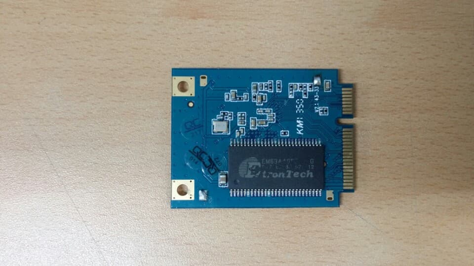
XR2WIZFI630A
Dec 20, 2015WiFi Module
Equipment Class
DTS - Digital Transmission System
XR2WIZFI250
Mar 26, 2014WiFi Module
Equipment Class
DTS - Digital Transmission System
XR2WIZFI220
Jun 26, 2011Wireless LAN Module
Equipment Class
DTS - Digital Transmission System
XR2WIZFI210
May 08, 2011Wireless LAN Module
Equipment Class
DTS - Digital Transmission System
XR2WIZ6000
Mar 10, 2010Serial to Wireless LAN Device Server
Equipment Class
DTS - Digital Transmission System