XRH-NPE109GEM3NFC
North Pole Engineering, Inc.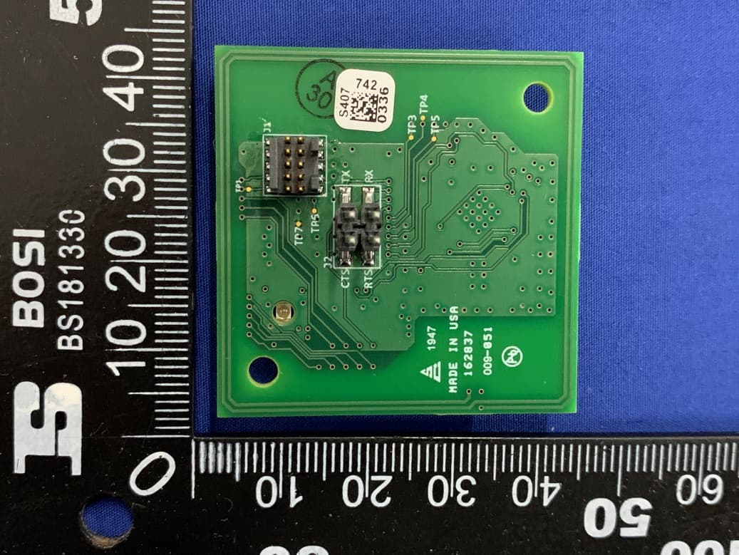
Click to zoom
Application Details
- Equipment Class
- DXX - Part 15 Low Power Communication Device Transmitter
- Date of Grant
- Mar 19, 2020
- Application Purpose
- Original Equipment
- Date of Application
- Mar 19, 2020
- Equipment Note
- GEM3NFC
- Frequency Range
- 13.56000000 - 13.56000000
- Company
- North Pole Engineering, Inc.
- Country
- United States
Documents & Files
Document Text
Text extracted from the exhibit documents filed with the FCC. Open a document above to read the original.
Users Manual
GEM3NFC Hardware Manual Version .2 October 30, 2019 NORTH POLE ENGINEERING INTELLECTUAL PROPERTY THIS DOCUMENT IS INTENDED FOR USE BY APPLICATION DEVELOPERS TO CREATE APPLICATIONS COMPATIBLE WITH THE NORTH POLE ENGINEERING GEM MODULE. USE OF THE TECHNICAL INFORMATION CONTAINED IN THIS DOCUMENT TO CREATE COMPETING HARDWARE TO THE NORTH POLE ENGINEERING GEM MODULE IS STRICTLY PROHIBITED. North Pole Engineering © North Pole Engineering Inc. 2019 221 N 1st St, Minneapolis, MN 55401 www.npe-inc.com 612.305.0440 Revision History VersionRevision DateChange History 0.1October 2, 2019Initial draft 0.2October 30, 2019Added mechanical drawing Table of Contents Revision History 2 ..................................................................................................................................... Overview and Key Features 4 ................................................................................................................ Features 4 ..................................................................................................................................................................... SpeciDication 5 ............................................................................................................................................ SpeciJication Summary 5 ....................................................................................................................................... Hardware SpeciDications 6 ...................................................................................................................... Block Diagrams 6 ...................................................................................................................................................... GEM3NFC Overview 7 ............................................................................................................................... Overview 7 ................................................................................................................................................................... Data, power, & I/O connector 7 ........................................................................................................................... Additional I/O 8 ......................................................................................................................................................... NFC Reader 8 .............................................................................................................................................................. NFC Antenna 8 ............................................................................................................................................................ GEM3 module 8 .......................................................................................................................................................... SpeciDications 8 .......................................................................................................................................... Operating Parameters 8 ......................................................................................................................................... Operating Modes 9 .................................................................................................................................... GymKit 9 ....................................................................................................................................................................... Smartphone Connection 10 .................................................................................................................................. GEM3NFC Considerations 12 ................................................................................................................. Antenna Characteristics 12 ................................................................................................................................... Mechanical Information 13 .................................................................................................................... Dimensions (in mm) 13 .......................................................................................................................................... Connecting GEM3NFC to Console MCU 13 .......................................................................................... GEM3NFC Host Protocol 14 .................................................................................................................... NFC Reader T4T card mode operation 14 ......................................................................................... ISO/IEC 1444A card mode 14 ............................................................................................................................. ISO/IEC 14443B card mode 15 ........................................................................................................................... Regulatory & Standards Information 15 ........................................................................................... FCC & Industry Canada 15 .................................................................................................................................... Federal Communication Commission (FCC) Radiation Exposure Statement: 15 ..................... FCC Labeling Requirements 16 ...................................................................................................................... FCC Warning: 16 ................................................................................................................................................... Industry Canada (IC) Warning: 17 ................................................................................................................ CE 19 ................................................................................................................................…
Text truncated - open the document above for the full version.
Cover Letter(s)
North Pole Engineering, Inc. Federal Communications Commission Authorization and Evaluation Division 1435 Oakland Mills Road Columbia, MD 21046 Confidentiality Request regarding application for certification of FCC ID: XRH-NPE109 Pursuant to Sections 0.457 and 0.459 of the Commission’s Rules, we hereby request permanently confidential treatment of information accompanying this application as outlined below: Exhibit Type File Name Block Diagram Block Diagram.pdf Schematics Schematics.pdf Operational Description Operational Description.pdf The above materials contain trade secrets and proprietary information not customarily released to the public. The public disclosure of these materials may be harmful to the applicant and provide unjustified benefits to its competitors. The applicant understands that pursuant to Section 0.457 of the Rules, disclosure of this application and all accompanying documentation will not be made before the date of the Grant for this application. Sincerely, (Signature) (Rick Gibbs) Rev 11/20/07
Cover Letter(s)
Applicant/Grantee NORTH POLE ENGINEERING, INC. FCC ID: XRH-NPE109 Modular Transmitters Request for Modular Approval Request for Limited Modular Approval Requirements EUT Conditions Comply(Y/N) Single Modular Approval Requirements 1 The radio elements of the modular transmitter must have their own shielding. The physical crystal and tuning capacitors may be located external to the shielded radio elements. Refer to the external photo Y 2 The modular transmitter must have buffered modulation/data inputs (if such inputs are provided) to ensure that the module will comply with modular approval requirements under conditions of excessive data rates or over- modulation. All input to the modules are buffered through microprocessor inputs. Y 3 The modular transmitter must have its own power supply regulation. Internal power regulators Refer to the Block-diagram Y 4 The modular transmitter must comply with the antenna and transmission system requirements. Refer to the internal photo Y 5 The modular transmitter must be tested in a stand- alone configuration, i.e., the module must not be inside another device during testing. Unless the transmitter module will be battery powered, it must comply with the AC line conducted requirements found in Section 15.207. AC or DC power lines and data input/output lines connected to the module must not contain ferrites, unless they will be marketed with the module (see Section 15.27(a)). The length of these lines shall be the length typical of actual use or, if that length is unknown, at least 10 centimeters to insure that there is no coupling between the case of the module and supporting equipment. Any accessories, peripherals, or support equipment connected to the module during testing shall be unmodified and commercially available (see Section 15.31(i)). The EUT was tested in a standalone configuration via a SD extension cable Refer to the test setup photo Y 6 The modular transmitter must be equipped with either a permanently affixed label or must be capable of electronically displaying its FCC identification number. Refer to the label and label location Y 7 The modular transmitter must comply with any specific rules or operating requirements that ordinarily apply to a complete transmitter and the manufacturer must provide adequate instructions along with the module to explain any such requirements. A copy of these instructions must be included in the application for equipment authorization. Refer to the user manual Y 8 The modular transmitter must comply with any applicable RF exposure requirements in its final configuration. Refer to the RF exposure statement for more details. Y A limited modular approval may be granted for single or split modular transmitters that do not comply with all of the above requirements, e.g., shielding, minimum signaling amplitude, buffered modulation/data inputs, or power supply regulation, if the manufacturer can demonstrate by alternative means in the application for equipment authorization that the modular transmitter meets all the applicable Limited modular approval also may be granted in those instances where compliance with RF exposure rules is demonstrated only for particular product configurations. The applicant for certification must state how control of the end product into which the module will be installed will be maintained such that full compliance of the end product is always ensured. Name and Title of the Applicant: Rick Gibbs/VP Engineering Date: 2020.03.13 Signature:
Cover Letter(s)
North Pole Engineering, Inc. Federal Communications Commission Authorization and Evaluation Division 1435 Oakland Mills Road Columbia, MD 21046 Date: 2020.03.13 SUBJECT: FCC Application for FCC ID: XRH-NPE109 To Whom It May Concern: We, the undersigned, hereby authorize _Harry Li_ _ at _CTC Laboratories, Inc. on our behalf, to apply to the Federal Communications Commission on our equipment. Any and all acts carried out by _ Harry Li_ on our behalf shall have the same effect as acts of our own. This is to advise that we are in full compliance with the Anti- Drug Abuse Act. We, the applicant, are not subject to a denial of federal benefits pursuant to Section 5301 of the Anti-Drug Act of 1988, 21 USC853a, and no party to the application is subject to a denial of federal benefits pursuant to that section. Regards, Printed Name: Rick Gibbs Signature: \\192.168.1.251\szctc\06 工程部\02 RF项目部\2020年案件\2月\CTC200113-036 GEM3NFC GEM3NFC0105\1.资料\1.3 申请资料 \letter\FCC\POA_Letter_140225.docx
Internal Photos
NFC Antenna
Test Report
CTC Laboratories, Inc. 1-2/F., Building 2, Jiaquan Building, Guanlan High-Tech Park, Shenzhen, Guangdong, P.R.C. Tel: +86-755-27521059 Fax: +86-755-27521011 Http://www.sz-ctc.com.cn TEST REPORT Report No........................................ : CTC20200188E01 FCC ID......................................: XRH-NPE109 IC ·········································: 11922A-NPE109 Applicant......................................... : North Pole Engineering Address(FCC)··············· ··············: 221 North First Street, Suite 310 Minneapolis, MN 55401, United States Address(IC)································: 221 1ST ST N Suite 310 Minneapolis MN 55401 United States Of America (Excluding The States Of Alaska) Manufacturer......................................: North Pole Engineering Address..............................................: 221 North First Street, Suite 310 Minneapolis, MN 55401, United States Product Name ................................ : GEM3NFC Trade Mark ....................................... : -- Model/Type reference ...................... : GEM3NFC0105 Listed Model(s) ................................ : -- Standard ........................................ : FCC CFR Title 47 Part 15 Subpart C Section 15.225 RSS-210:2019; RSS-GEN:210 Date of receipt of test sample......: Feb. 26, 2020 Date of testing..........................: Feb. 28, 2020 to Mar. 07, 2020 Date of issue............................: Mar. 10, 2020 Result....................................: PASS Compiled by: (Printed name + signature) Zaki Zhang Supervised by: ( Printed name + signature) Miller Ma Approved by: ( Printed name + signature) Walter Chen Testing Laboratory Name .............. : CTC Laboratories, Inc. Address ............................................ : 1-2/F., Building 2, Jiaquan Building, Guanlan High-Tech Park, Shenzhen, Guangdong, P.R.C. This test report may be duplicated completely for legal use with the approval of the applicant. It should not be reproduced except in full, without the written approval of our laboratory. The client should not use it to claim product endorsement by CTC. The test results in the report only apply to the tested sample. The test report shall be invalid without all the signatures of testing engineers, reviewer and approver. Any objections must be raised to CTC within 15 days since the date when the report is received. It will not be taken into consideration beyond this limit. The test report merely correspond to the test sample. Page 2 of 32 Report No.: CTC20200188E01 CTC Laboratories, Inc. 1-2/F., Building 2, Jiaquan Building, Guanlan High-Tech Park, Shenzhen, Guangdong, P.R.C. Tel.: (86)755-27521059 Fax: (86)755-27521011 Http://www.sz-ctc.org.cn For anti-fake verification, please visit the official website of Certification and Accreditation Administration of the People’s Republic of China : http://yz.cnca.cn Table of Contents Page 3. TEST SUMMARY ....................................................................................................................................................... 3 3.1. TEST STANDARDS .......................................................................................................................................................... 3 3.2. REPORT VERSION .......................................................................................................................................................... 3 3.3. TEST DESCRIPTION ........................................................................................................................................................ 4 3.4. TEST FACILITY .............................................................................................................................................................. 5 3.5. MEASUREMENT UNCERTAINTY ........................................................................................................................................ 5 3.6. ENVIRONMENTAL CONDITIONS ........................................................................................................................................ 6 3.7. EUT OP E RAT I ON S TAT E .................................................................................................................................................. 6 2. GENERAL INFORMATION .......................................................................................................................................... 7 2.1. CLIENT INFORMATION ................................................................................................................................................... 7 2.2. GENERAL DESCRIPTION OF EUT ...................................................................................................................................... 7 2.3. ACCESSORY EQUIPMENT INFORMATION ............................................................................................................................ 7 2.4. MEASUREMENT INSTRUMENTS LIST ................................................................................................................................. 8 3. TEST ITEM AND RESULTS ........................................................................................................................................ 10 3.1. CONDUCTED EMISSION ................................................................................................................................................ 10 3.2. RADIATED EMISSION ................................................................................................................................................... 13 3.3. OCCUPIED BANDWIDTH 20 DB BANDWIDTH .................................................................................................................... 23 3.4. FIELD STRENGTH OF THE FUNDAMENTAL ......................................................................................................................... 25 3.5. FREQUENCY STA …
Text truncated - open the document above for the full version.
Test Setup Photos
Below 30MHz Below 1000MHz Conducted Emission
Contact Information
Applicant
Rick Gibbs(VP Engineering)
Test Firm
CTC Laboratories, Inc.Totti Zhao
[email protected]+8675527521059
Technical Specifications
| # | Rule Parts | Frequency Range | Power Output |
|---|---|---|---|
| 1 | 15C | 13.56 MHz - 13.56 MHz | - |
Other Applications from North Pole Engineering, Inc.
XRH-NPE111
Apr 02, 2026Mobile Transceiver
Equipment Class
DTS - Digital Transmission System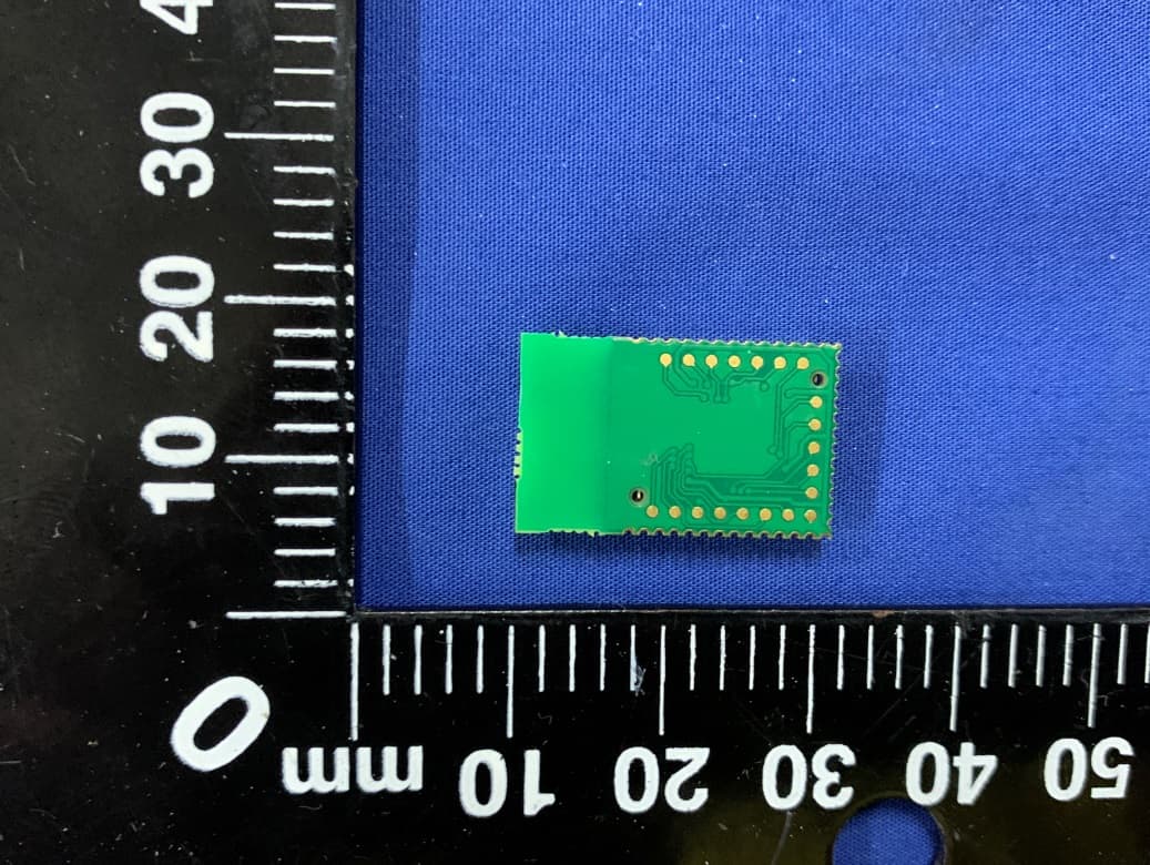
XRH-NPE105
Mar 11, 2020GEM3
Equipment Class
DTS - Digital Transmission System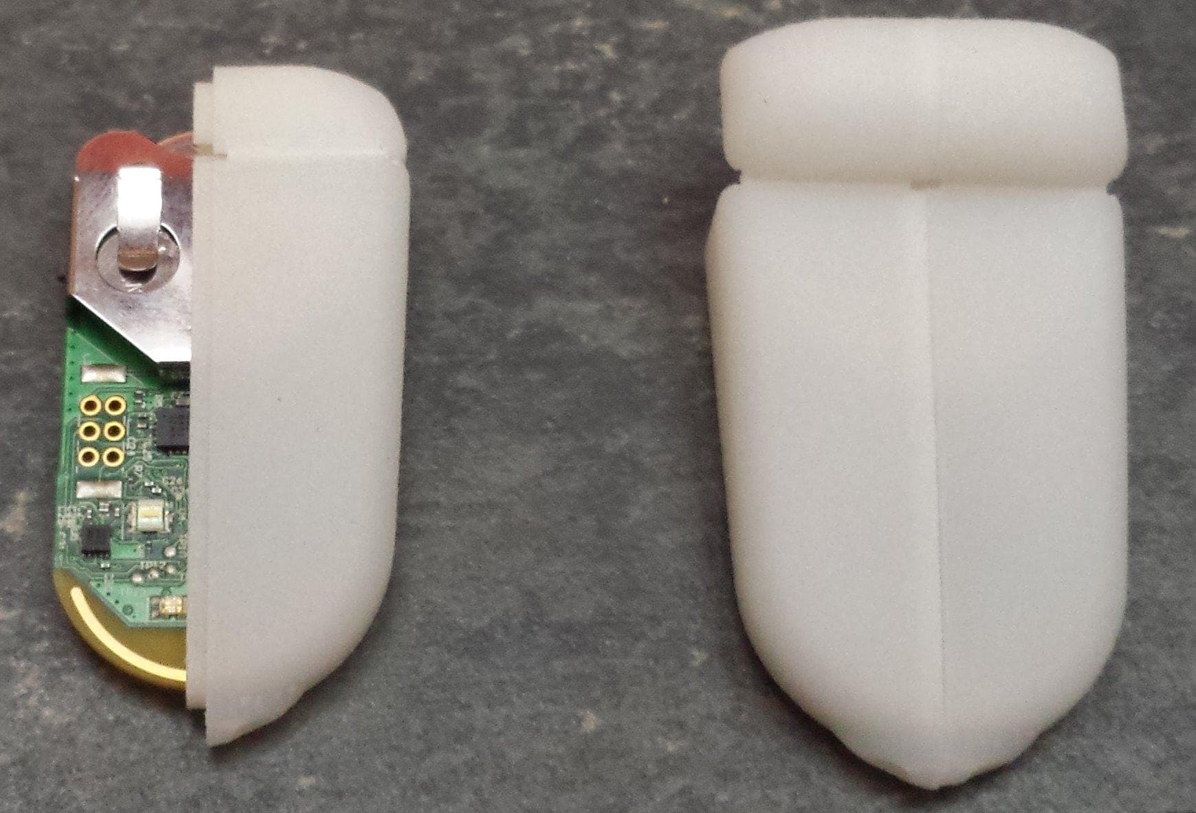
XRH-414ANT
May 20, 2014ANT+ device. Battery powered or DC wall supply powered.
Equipment Class
DXX - Part 15 Low Power Communication Device Transmitter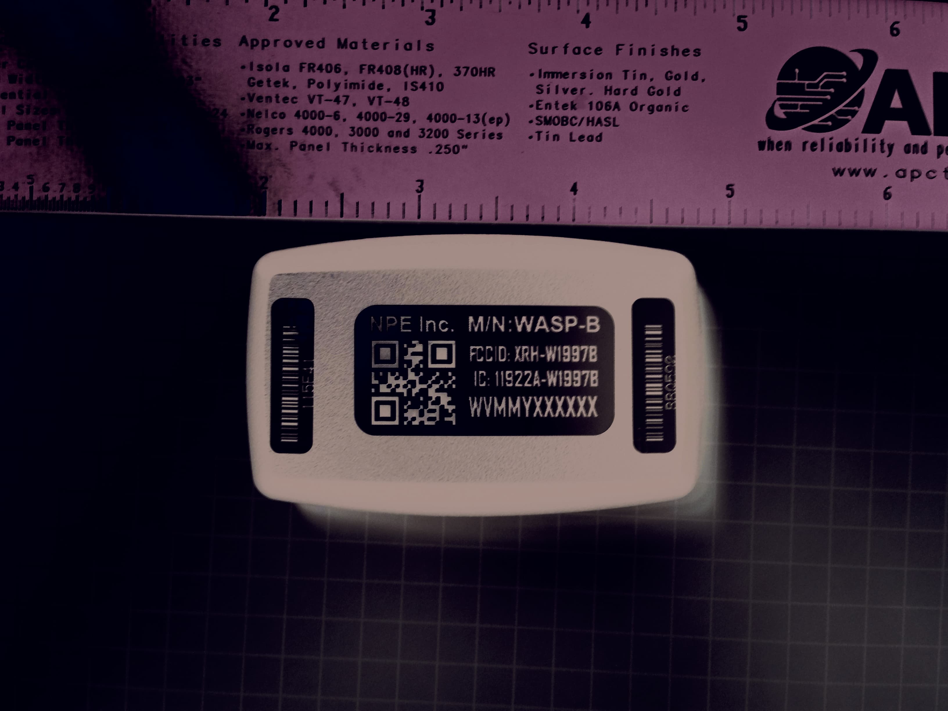
XRH-W1997B
May 20, 2014WiFi to ANT+ bridge device. Battery powered or DC wall supply powered.
Equipment Class
DTS - Digital Transmission System
XRH-1997
Apr 17, 2010WIRELESS WLAN MODULE
Equipment Class
DXX - Part 15 Low Power Communication Device Transmitter