XRH-W1997BWiFi to ANT+ bridge device. Battery powered or DC wall supply powered.
North Pole Engineering, Inc.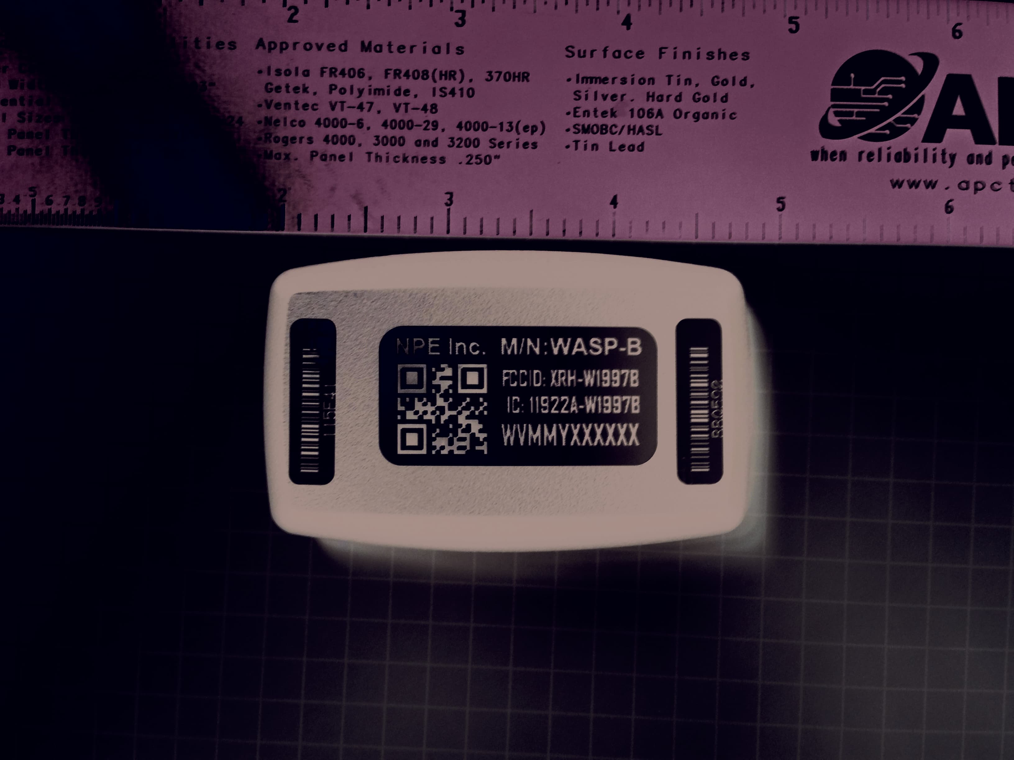
Click to zoom
Application Details
- Equipment Class
- DTS - Digital Transmission System
- Date of Grant
- May 20, 2014
- Application Purpose
- Original Equipment
- Date of Application
- May 20, 2014
- Equipment Note
- WiFi to ANT+ bridge device. Battery powered or DC wall supply powered.
- Frequency Range
- 2412.00000000 - 2462.00000000
- Company
- North Pole Engineering, Inc.
- Country
- United States
Documents & Files
Document Text
Text extracted from the exhibit documents filed with the FCC. Open a document above to read the original.
Users Manual
© 2013 - 2014 North Pole Engineering, Inc. WASP User Manual Revision: 2.2.6 © 2013 - 2014 North Pole Engineering, Inc. 2 WASP User Manual 1 Introduction WASP is a standalone unit providing a bridge for ANT+ devices to communicate wirelessly through Wi-Fi networks, to other devices on the local network or over the Internet. Utilizing an 8-channel ANT+ receiver, on-board memory, power management circuitry and rechargeable Li-Ion battery, WASP provides a data gateway for monitoring, recording and analyzing ANT+ data remotely. WASP connects ANT+ devices to wireless networks for monitoring and data collection purposes. For example ANT+ home scales, pulse-oximeter monitors, and blood glucose monitors as well as heart rate monitors and all other ANT enabled devices are all able to use this bridge module to communicate their data to central monitoring stations via the Wi-Fi network. WASP is capable of receiving data wirelessly, from all certified ANT+ devices in the local area that share the same ANT frequency. ANT+ device state is encapsulated as standard UDP messages, allowing it to be routed through local networks, through the Internet or directly to any Wi-Fi connected device. WASP can be configured directly over the network with a configuration utility or a web browser. WASP is also capable of sending data to any ANT radio in range that is capable of receiving data packets. An Application Programmers Interface is available to OEM partners, allowing WASP integration into custom applications needing wireless connectivity to ANT enabled devices at ranges which exceed the typical ANT radio reach. WASP Wi-Fi is able to join existing networks with common security protocols, or create its own access point allowing WASPs and application end point devices (smart phones, tablet computers, Personal Computers, etc.) to join and share information locally. WASP will run for up to six hours on its internal Li-Ion battery when hosting its own network as the network manager or up to 18 hours when joining an existing network. Battery life is dependent on the amount of ANT traffic local to the WASP. For fixed installation environments, WASP can be powered from a USB power source. In addition to the periodic streaming protocols, WASP supports ANT-FS sessions when coupled with a Wi-Fi application or web host to manage the authentication, and file transfer requests. When WASP is configured in ANT-FS mode, it searches for ANT-FS beacons. When a beacon is found, it commands the device sending the beacon to change frequencies and await the authenticate command. The Wi-Fi endpoint application or web host is then notified of the connection and control is passed off to the host device to manage the data transfer. WASP monitors the transactions assisting in connection management during the transfer process. Once the transfer is complete (the connection is either closed or lost), it resumes searching for other ANT-FS devices. WASP can also be used as a bridge between multiple ANT+ nodes in distributed ANT+ network topologies. Since ANT+ is a personal area network, it has a typical range of approximately 10 to 20 meters. If the ANT+ network is used as a mesh or hub and spoke topology, WASP can join networks together that would normally not be able to communicate with each other because of range limitations. WASP is ANT+ certified and complies with all ANT+ device profiles. © 2013 - 2014 North Pole Engineering, Inc. Scope 3 2 Scope This document provides a general introduction to using WASP. It includes information on button operations, LED indicators, powering/charging the device, and Wi-Fi configuration. 3 What's New Here are the updates for the latest release and previous releases. Release 2.2.6 1. Added regulatory section. 2. Added unit safety section. Release 2.2.5 3. Default operation for button press or cold boot selected by new "Infrastructure Enabled" flag. 4. Cold boot or SW Reset from SET_CONFIG or web pages now goes directly into operation. 5. Charger connect always starts WASP if not already in operational mode. Release 2.1.23 1. Changed default provisioning mode from AdHoc to Limited AP. 2. WASP can now join non-broadcasting networks. 3. Button handling changes - Green LED turns on immediately for button press. Button powers on straight into infrastructure. Button press while attempting to join infrastructure drops into Limited AP/AdHoc mode. 4. Multiple bug fixes. Release 2.1.9 1. Added AdHoc Web provisioning mode and ability to switch between AdHoc Web and AP Web. 2. Made AdHoc Web the default provisioning mode. 3. Multiple bug fixes. Release 2.1.0 1. ANTFS application specific disconnect parameter added. Release 2.0.17 1. ANTFS functionality added to download and forward files from ANTFS enabled devices. 2. Packet Saver mode added to concatenate multiple ANT packets into a single UDP packet to reduce Wi-Fi network traffic. 3. Infrastructure Mode no longer uses a channel setting. It instead scans all channels for the preconfigured network name. 4. WPS Mode added. 5. WASP now available with SPI mode ANT radios for higher throughput. 6. Updates for more intuitive usage and user feedback. © 2013 - 2014 North Pole Engineering, Inc. 7. Multiple bug fixes. Release 1.6.1 © 2013 - 2014 North Pole Engineering, Inc. Scope 5 4 WASP User Manual 1. Functional packet protocol change from point to point packet routing to local area UDP multicast packets greatly increasing the number of Wi-Fi endpoints capable of receiving data from a WASP while at the same time reducing the number of transactions required to supply the data. 2. Support for both TCP and UDP type connections. 3. Enabled TCP connection for managing WASP configuration/control operations to a single endpoint instead of UDP control from multiple end points requesting control. 4. Singular IP routing entry for supporting connection to web services outside the local Wi-Fi network. 5. Improved user interface (button/LED) operation 6. Configured network persistence…
Text truncated - open the document above for the full version.
Attestation Statements
TÜV SÜD AMERICA INC 10040 Mesa Rim Road San Diego, CA 92121-2912 Phone: 858 678 1400 FAX: 858 546 0364 TÜV SÜD America Inc. (San Diego) May 19, 2014 TUV SUD BABT Octagon House, Concorde Way Segensworth Rd N, Fareham PO15 5RL FCC ID: XRH-W1997B IC: 11922A-WI997B North Pole Engineering Inc. 221 1 st St N, Suite 310 Minneapolis, MN 55401 RE: Attestation statements: • Supplied test report for the approved WLAN module (Report Number: 31051809.001 issued by TUV Rheinland of North America, Inc.) was written as per RSS-210 Issue 7 June 2007. To show compliance with RSS-210 Issue 8 December 2010, the List of Changes were reviewed (Page i of Issue 8) and were verified that no change transpired under Annex 8 (Frequency Hopping and Digital Modulation Systems Operating in the Bands 902-928 MHz, 2400-2483.5 MHz and 5725- 5850 MHz) or other Sections that will influence the original test results. Therefore it is concluded that the WLAN RSS-210 test report presented is compliant to the requirements of RSS-210 Issue 8 December 2010. • The test report number 31051809.001 and 110815B filed under FCC ID: YOPGS1011MIP/IC: 9154A-GS1011MIP and FCC ID: O6R1823/IC:3797A-1823 respectively were also applicable for the above FCC ID (XRH-W1997B) and IC (11922A-WI997B) approval as the modules are identical and there have been no changes to the module/antenna, and therefore the results remain representative of this product for FCC Part 15C and IC RSS-210. • The test reports presented represent the current model RF performance and meet the current FCC and IC rules. Sincerely, Ferdinand S. Custodio EMC/Senior Wireless Test Engineer
Cover Letter(s)
221 North151 Street Suite310 Minneapolis,Mn. 55401 www.NPE-INC.com April28, 2014 '% , TUVSUOBABTTCB OctagonHouse, SegensworthRoad, Fareham, Hampshire, P0155RL FCC10: XRH-W1997B IC: 11922A-W1997B DearSir or Madam: We (NPE,Inc.,221 North1ST ST, Suite310,Minneapolis,MN 55401),herebyauthorize FerdinandCustodioof TUVSUOAmerica(10040MesaRim Road,San Diego,CA 92121- 2912)to act as our agentin all mattersrelatingto applicationsfor equipmentauthorization, includingthe signingof all documentsrelatingto thesematers. Thisauthorizationexpireson 25 Nov, i q~P'L~IJI CompanyOfficer: JosephTretter(signedby FCClistedGranteecontact) TelephoneNumber:(612)305-0440email:[email protected] n~ Silicon& Software . . . . . . . . . . . . . . . . . . . . . . . . . .
Cover Letter(s)
221North1 st Street Suite310 Minneapolis,Mn.55401 www.NPE-INC.com April22, 2014 TUVSUOBABTTCB OctagonHouse, SegensworthRoad, Fareham, Hampshire, P0155RL ConfidentialityRequest FCC10: XRH-W1997B DearSir or Madam: Pursuantto Sections0.457(d) (1) (ii) and 0.459of the Commission'sRules,NPE,Inc. herebyrequestspermanentconfidentialtreatmentof informationaccompanyingthis applicationas outlinedbelow: • Schematics • Bill of materials/Partslist • Blockdiagrams • OperationDescription NPE,Inc. alsoherebyrequestsshorttermconfidentialtreatmentof information accompanyingthis applicationas outlinedbelowfor a periodof (up to 180)days: • Internalphotos The abovematerialscontaintradesecretsand proprietaryinformationnot customarily releasedto the public.The publicdisclosureof thesematerialsmightbe harmfulto the Applicantand provideunjustifiedbenefitsto its competitors. The Applicantunderstandsthat pursuantto Rule0.457(d)(1 )(ii), disclosureof this Applicationand all accompanyingmaterialswillot be madebeforethe dateof the Grantfor :i:C:~~~~ation4~ R CompanyOfficer: JosephTretter(signedby FCClistedGranteecontact) TelephoneNumber:(612)305-0440email:[email protected] n~ Silicon& Software
Test Report
The test results contained in this report refer exclusively to the product(s) presented for testing. No liability may be assumed for models or products not referred to herein. This test report may not be published or duplicated in part without permission of the testing body. This test report by itself does not constitute authorization for the use of any TUV Rheinland test mark. This report must not be used by the applicant to claim product certification, approval, or endorsement by NVLAP, NIST, or any agency of the federal government. Report Number: 31051809.001 Page 1 of 87 EUT: Wi-Fi Module Model: GS1011MIP EMC / Rev 9/9/2010 FCCID: YOPGS1011MIP, IC ID: 9154AGS1011MIP Emissions Test Report EUT Name: Wi-Fi Module Model No.: GS1011MIP CFR 47 Part 15.247 2010 and RSS 210: 2007 Prepared for: Ron Green Gainspan Corporation 125 S. Market St. Suite 400 San Jose, CA 95113-2292 Tel: (408) 673-2900 Fax: (408) 673-2901 Prepared by: TUV Rheinland of North America, Inc. 1279 Quarry Lane Pleasanton, CA 94566 Tel: (925) 249-9123 Fax: (925) 249-9124 http://www.tuv.com/ Report/Issue Date: 12 July 2010 Report Number: 31051809.001 Statement of Compliance The test results contained in this report refer exclusively to the product(s) presented for testing. No liability may be assumed for models or products not referred to herein. This test report may not be published or duplicated in part without permission of the testing body. This test report by itself does not constitute authorization for the use of any TUV Rheinland test mark. This report must not be used by the applicant to claim product certification, approval, or endorsement by NVLAP, NIST, or any agency of the federal government. Report Number: 31051809.001 Page 2 of 87 EUT: Wi-Fi Module Model: GS1011MIP EMC / Rev 9/9/2010 FCCID: YOPGS1011MIP, IC ID: 9154AGS1011MIP Manufacturer: Gainspan Corporation 125 S. Market St. Suite 400 San Jose, CA 95113-2292 (408) 673-2900 Requester / Applicant: Ron Green Name of Equipment: Wi-Fi Module Model No. GS1011MIP Type of Equipment: Intentional Radiator Application of Regulations: CFR 47 Part 15.247 2010 and RSS 210: 2007 Test Dates: July 1 to July 8, 2010 Guidance Documents: Emissions: ANSI C63.10: 2009 Test Methods: Emissions: ANSI C63.10: 2009 The electromagnetic compatibility test and documented data described in this report has been performed and recorded by TUV Rheinland, in accordance with the standards and procedures listed herein. As the responsible authorized agent of the EMC laboratory, I hereby declare that the equipment described above has been shown to be compliant with the EMC requirements of the stated regulations and standards based on these results. If any special accessories and/or modifications were required for compliance, they are listed in the Executive Summary of this report. This report must not be used to claim product endorsement by NVLAP or any agency of the U.S. Government. This report contains data that are not covered by NVLAP accreditation. This report shall not be reproduced except in full, without the written authorization of TUV Rheinland of North America. Jeremy Luong Conan Boyle Test Engineer Date NVLAP Signatory Date US5254 2932M-1 Table of Contents The test results contained in this report refer exclusively to the product(s) presented for testing. No liability may be assumed for models or products not referred to herein. This test report may not be published or duplicated in part without permission of the testing body. This test report by itself does not constitute authorization for the use of any TUV Rheinland test mark. This report must not be used by the applicant to claim product certification, approval, or endorsement by NVLAP, NIST, or any agency of the federal government. Report Number: 31051809.001 Page 3 of 87 EUT: Wi-Fi Module Model: GS1011MIP EMC / Rev 9/9/2010 FCCID: YOPGS1011MIP, IC ID: 9154AGS1011MIP 1 Executive Summary _______________________________________________________ 8 1.1 Scope______________________________________________________________________ 8 1.2 Purpose____________________________________________________________________ 8 1.3 Summary of Test Results _____________________________________________________ 8 1.4 Special Accessories __________________________________________________________ 8 1.5 Equipment Modifications _____________________________________________________ 8 2 Laboratory Information ____________________________________________________ 9 2.1 Accreditations & Endorsements _______________________________________________ 9 2.1.1 US Federal Communications Commission _______________________________________________ 9 2.1.2 NIST / NVLAP ____________________________________________________________________ 9 2.1.3 Canada – Industry Canada ___________________________________________________________ 9 2.1.4 Japan – VCCI _____________________________________________________________________ 9 2.1.5 Acceptance by Mutual Recognition Arrangement _________________________________________ 9 2.2 Test Facilities ______________________________________________________________ 10 2.2.1 Emission Test Facility _____________________________________________________________ 10 2.2.2 Immunity Test Facility _____________________________________________________________ 10 2.3 Measurement Uncertainty ___________________________________________________ 11 2.3.1 Sample Calculation – radiated & conducted emissions ____________________________________ 11 2.3.2 Measurement Uncertainty Emissions __________________________________________________ 12 2.4 Calibration Traceability _____________________________________________________ 12 3 Product Information ______________________________________________________ 13 3.1 Product Description ________________________________________________________ 13 3.2 Equipment Configuration ___________________________________________________ 13 3.3 Operating Mode ___________________________________________________________ 13 3.4 Unique Antenna…
Text truncated - open the document above for the full version.
Test Setup Photos
TUV Rheinland Test Setup Photo 1279 Quarry Lane, Ste. A, Pleasanton, CA 95466 Tel: (925) 249-9123, Fax: (925) 249-9124 Report Number: 31051809.001 Page 1 of 12 EUT: WiFi Module Model: GS1011MIP EMC / Rev 9/30/2010 FCCID: YOPGS1011MIP, IC ID: 9154AGS1011MIP 1 Photo 1.1 Test Setup Photo Figure 1: 30 MHz to 1000 MHz Radiated Emission Setup (Front View) TUV Rheinland Test Setup Photo 1279 Quarry Lane, Ste. A, Pleasanton, CA 95466 Tel: (925) 249-9123, Fax: (925) 249-9124 Report Number: 31051809.001 Page 2 of 12 EUT: WiFi Module Model: GS1011MIP EMC / Rev 9/30/2010 FCCID: YOPGS1011MIP, IC ID: 9154AGS1011MIP Figure 2: 30 MHz to 1000 MHz Radiated Emission Setup (Rear View) TUV Rheinland Test Setup Photo 1279 Quarry Lane, Ste. A, Pleasanton, CA 95466 Tel: (925) 249-9123, Fax: (925) 249-9124 Report Number: 31051809.001 Page 3 of 12 EUT: WiFi Module Model: GS1011MIP EMC / Rev 9/30/2010 FCCID: YOPGS1011MIP, IC ID: 9154AGS1011MIP Figure 3: Test Setup for 1GHz to 18GHz (Front View) TUV Rheinland Test Setup Photo 1279 Quarry Lane, Ste. A, Pleasanton, CA 95466 Tel: (925) 249-9123, Fax: (925) 249-9124 Report Number: 31051809.001 Page 4 of 12 EUT: WiFi Module Model: GS1011MIP EMC / Rev 9/30/2010 FCCID: YOPGS1011MIP, IC ID: 9154AGS1011MIP Figure 4: Test Setup for 1GHz to 18GHz (Rear View) TUV Rheinland Test Setup Photo 1279 Quarry Lane, Ste. A, Pleasanton, CA 95466 Tel: (925) 249-9123, Fax: (925) 249-9124 Report Number: 31051809.001 Page 5 of 12 EUT: WiFi Module Model: GS1011MIP EMC / Rev 9/30/2010 FCCID: YOPGS1011MIP, IC ID: 9154AGS1011MIP Figure 5: Test Setup for 18 GHz to 26GHz (Front View) TUV Rheinland Test Setup Photo 1279 Quarry Lane, Ste. A, Pleasanton, CA 95466 Tel: (925) 249-9123, Fax: (925) 249-9124 Report Number: 31051809.001 Page 6 of 12 EUT: WiFi Module Model: GS1011MIP EMC / Rev 9/30/2010 FCCID: YOPGS1011MIP, IC ID: 9154AGS1011MIP Figure 6: Test Setup for 18 GHz to 26GHz (Rear View) TUV Rheinland Test Setup Photo 1279 Quarry Lane, Ste. A, Pleasanton, CA 95466 Tel: (925) 249-9123, Fax: (925) 249-9124 Report Number: 31051809.001 Page 7 of 12 EUT: WiFi Module Model: GS1011MIP EMC / Rev 9/30/2010 FCCID: YOPGS1011MIP, IC ID: 9154AGS1011MIP Figure 7: Radiated Emission Setup on X-Axis TUV Rheinland Test Setup Photo 1279 Quarry Lane, Ste. A, Pleasanton, CA 95466 Tel: (925) 249-9123, Fax: (925) 249-9124 Report Number: 31051809.001 Page 8 of 12 EUT: WiFi Module Model: GS1011MIP EMC / Rev 9/30/2010 FCCID: YOPGS1011MIP, IC ID: 9154AGS1011MIP Figure 8: Radiated Emission Setup on Y-Axis TUV Rheinland Test Setup Photo 1279 Quarry Lane, Ste. A, Pleasanton, CA 95466 Tel: (925) 249-9123, Fax: (925) 249-9124 Report Number: 31051809.001 Page 9 of 12 EUT: WiFi Module Model: GS1011MIP EMC / Rev 9/30/2010 FCCID: YOPGS1011MIP, IC ID: 9154AGS1011MIP Figure 9: Radiated Emission Setup on Z-Axis TUV Rheinland Test Setup Photo 1279 Quarry Lane, Ste. A, Pleasanton, CA 95466 Tel: (925) 249-9123, Fax: (925) 249-9124 Report Number: 31051809.001 Page 10 of 12 EUT: WiFi Module Model: GS1011MIP EMC / Rev 9/30/2010 FCCID: YOPGS1011MIP, IC ID: 9154AGS1011MIP Figure 10: AC Conducted Emission (Front View) TUV Rheinland Test Setup Photo 1279 Quarry Lane, Ste. A, Pleasanton, CA 95466 Tel: (925) 249-9123, Fax: (925) 249-9124 Report Number: 31051809.001 Page 11 of 12 EUT: WiFi Module Model: GS1011MIP EMC / Rev 9/30/2010 FCCID: YOPGS1011MIP, IC ID: 9154AGS1011MIP Figure 11: AC Conducted Emission (Side View) TUV Rheinland Test Setup Photo 1279 Quarry Lane, Ste. A, Pleasanton, CA 95466 Tel: (925) 249-9123, Fax: (925) 249-9124 Report Number: 31051809.001 Page 12 of 12 EUT: WiFi Module Model: GS1011MIP EMC / Rev 9/30/2010 FCCID: YOPGS1011MIP, IC ID: 9154AGS1011MIP Figure 12: Conducted Test at RF Output Port for WiFi Module
Contact Information
Applicant
Rick Gibbs(VP Engineering)
Test Firm
TUV Rheinland of North America Inc.David Spencer
Technical Specifications
| # | Rule Parts | Frequency Range | Power Output |
|---|---|---|---|
| 1 | 15C | 2.41 GHz - 2.46 GHz | 80.00 mW |
Other Applications from North Pole Engineering, Inc.
XRH-NPE111
Apr 02, 2026Mobile Transceiver
Equipment Class
DTS - Digital Transmission System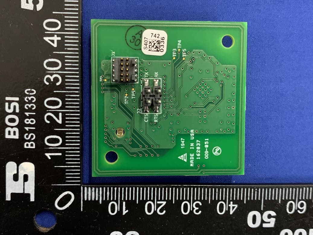
XRH-NPE109
Mar 19, 2020GEM3NFC
Equipment Class
DXX - Part 15 Low Power Communication Device Transmitter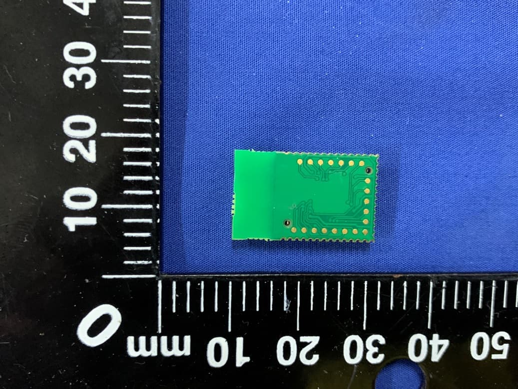
XRH-NPE105
Mar 11, 2020GEM3
Equipment Class
DTS - Digital Transmission System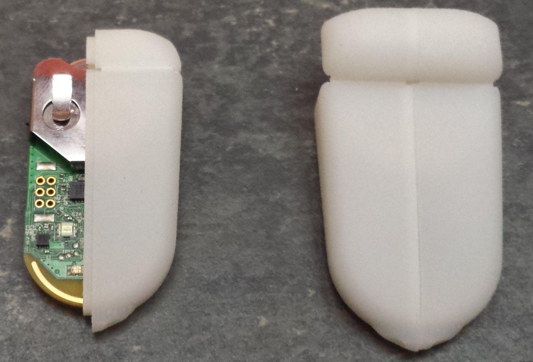
XRH-414ANT
May 20, 2014ANT+ device. Battery powered or DC wall supply powered.
Equipment Class
DXX - Part 15 Low Power Communication Device Transmitter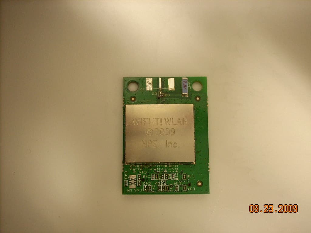
XRH-1997
Apr 17, 2010WIRELESS WLAN MODULE
Equipment Class
DXX - Part 15 Low Power Communication Device Transmitter