XS5-M7785HP19PION-M Remote Unit for cellular systems
Andrew Wireless System
Click to zoom
Application Details
- Equipment Class
- AMP - Amplifier
- Date of Grant
- May 17, 2012
- Application Purpose
- Original Equipment
- Date of Application
- May 17, 2012
- Equipment Note
- ION-M Remote Unit for cellular systems
- Frequency Range
- 1930.00000000 - 1995.00000000
- Company
- Andrew Wireless System
- Country
- Germany
Documents & Files
Document Text
Text extracted from the exhibit documents filed with the FCC. Open a document above to read the original.
Users Manual
Installation Instruction The Remote Unit, Extension Unit or Master Unit has to be mounted by proffessionel / special trained installer. 1.1. MECHANICAL INSTALLATION 1.1.1. General Read the health and safety warnings in chapter 1.3. 1. Do not ins tall the unit in a way or at a place where the specifications outlined in the Environmental and Safety Specifications leaflet of the supplier are not met. 2. It is recommended only to use the mounting hardware delivered by the supplier. If different mounting hardware is used, the specifications for stationary use of the Remote Unit must not be exceeded. Note: Exceeding the specified load limits may cause the loss of warranty! 3. The unit is considerably heavy. Make sure that a suitable mounting surface is used. Ensure there is adequate manpower to handle the weight of the system. 4. Due to pow er dissipation, the Remote Unit may reach a very high temperature. Ensure sufficient airflow for ventilation as specified in the individual mounting procedures. 5. When connecting and mounting the cables (RF, optical, mains, ...) ensure no water can penetrate into the unit through these cables. 6. Also observe all additional rules or restrictions regarding mounting that depend on the type of Remote Unit. For details refer to chapter 7.2.2 Mechanical Specification. Install the unit vertically with the fan unit at the top. A maximum tilt angle of 25° from a vertical position must be kept, as in the following illustrations: 7. A spacing of 40 mm (1.58 inch) around the unit is required. 8. To ensure sufficient airflow when mounting the unit in enclosed spaces, two lid openings (one for the air inlet and the other for the air outlet) have to be provided. Do not block these air inlets and outlets when mounting the Remote Unit. The size of each opening must equal at least 17 x 17 cm (290 cm 2 ). Make sure, too, there is no thermal short circuit between the air inlet and air outlet. If any different or additional mounting material is used, ensure that the mounting remains as safe as the mounting designed by the manufacturer. Ensure that the static and dynamic strengths are adequate for the environmental conditions of the site. The mounting itself must not vibrate, swing or move in any way that might cause damage to the Remote Unit. Specified torques have to be observed for certain mounting procedures according to the following table: Type Tallow-drop screws Hex nuts Spacing bolts PG (plastic) PG (aluminium) Thread M 4 M 8 M 4 M 8 PG 13.5 PG 29 Specified torques 3.3 Nm 27 Nm 2.3 Nm 27 Nm 3.75 Nm 10 Nm Specified torques Note: To avoid damage when mounting the unit, always make sure that the M8 washers (DIN9021 or DIN125 depending on the mounting kit) are placed behind and in front of the mounting drillings of the unit. The mounting procedures for a stand-alone Remote Unit without optional accessories are described and illustrated in the following sections. For further information regarding special mounting procedures including mounting of accessory equipment, please see separate manual. 1.2. ELECTRICAL INSTALLATION 1.2.1. General Read the health and safety warnings in chapter 1.1. 1. This unit contains dangerous voltages. Loss of life, severe personal injury or property dam age can be the result if the instructions contained in this manual are not followed. 2. It is compulsory to ground the unit before connecting power supply. A grounding bolt is provided on the cabinet to connect the ground-bonding cable. 3. Although the Remote Unit is internally protected against overvoltage, it is strongly recommended to earth the antenna cables close to the antenna connectors of the Remote Unit for protection against atmospheric discharge. In areas with strong lightning it is strongly recommended to insert additional lightning protection. 4. If the mains connector of the Remote Unit is not easily accessible, a disconnect device in the mains circuit must be provided within easy reach. 5. Before connecting or disconnecting the mains connector at the Remote Unit, ensure that mains supply is disconnected. 6. Make sure that an appropriate branch circuit breaker and an overcurrent limiting device are connected between mains and Remote Unit. 7. An external circuit breaker is mandatory as disconnect device. This circuit breaker should be readily available for the operator. For the U.S. and Canada, installation has to be done in accordance with the NEC (National Electronic Code). The external circuit breaker has to be a branch circuit breaker rated 20 A for 110 Vac mains. 8. A field wiring box with conduit must be used for the installation. Use a wire harness rated for AC mains with at least AWG14 size. 9. A connection of mains supply to a power socket requires the power socket to be nearby the Remote Unit. 10. Incorrectly wired connections can destroy electrical and electronic components. 11. To avoid corrosion at the connectors caused by electrochemical processes, the material of the cable connectors must not cause a higher potential difference than 0.6 V (see electrochemical contact series). 12. Use an appropriate torque wrench for the coupling torque (25 N-m / 19 ft lb) of 7/16-DIN connectors with 1 ¼-inch opening to tighten the 7/16-type antenna connectors. For example, use torque wrench of item no. 244377 available from the Andrew e-catalog. Do NOT use your hands or any other tool (e.g. a pair of pliers)! This might cause damage to the connector and lead to a malfunction of the Remote Unit. 13. For unstabilized electric networks which frequently generate spikes, it is advised to use a voltage limiting device. 14. The unit complies with the surge requirement according to EN 61000-4-5 (fine protection); however, it is recommended to install an additional medium (via local supply connection) and/or coarse protection (external surge protection) depending on the individual application in order to avoid damage caused by overcurrent. 15. Observe the labels on the front panels before co…
Text truncated - open the document above for the full version.
Users Manual
Optical Remote Unit ION™-M7HP/7HP/85HP/19P (W1-cabinet) Manual MF0145A8A Manual for ION-M7HP/7HP/85HP/19P (W1-Cabinet) Page 2 MF0145A8A_FCC modif.doc © Copyright 2012 CommScope, Inc. All rights reserved. CommScope Solutions is a trademark of CommScope, Inc. All information contained in this manual has been revised thoroughly. Yet CommScope Solutions accepts no liability for any omissions or faults. CommScope Solutions reserves the right to change all hardware and software characteristics without notice. Names of products mentioned herein are used for identification purposes only and may be trademarks and / or registered trademarks of their respective companies. No parts of this publication may be reproduced, stored in a retrieval system, transmitted in any form or by any means, electronical, mechanical photocopying, recording or otherwise, without prior written permission of the publisher. Andrew Wireless Systems GmbH, 03-May-2012 Page 3 TABLE OF CONTENTS 1. GENERAL 5 1.1. USED ABBREVIATIONS 5 1.2. HEALTH AND SAFETY WARNINGS 6 1.3. ABOUT COMMSCOPE SOLUTIONS 8 1.4. INTERNATIONAL CONTACT ADDRESSES FOR CUSTOMER SUPPORT 9 2. INTRODUCTION 12 2.1. PURPOSE 12 2.2. THE ION-M7HP/7HP/85HP/19P (INTELLIGENT OPTICAL NETWORK; MMR) 12 2.3. VSWR ALARMING OPTION 13 3. COMMISSIONING 15 3.1. MECHANICAL INSTALLATION 15 3.1.1. General 15 3.1.2. Wall-Mounting Procedure 17 3.2. ELECTRICAL INSTALLATION 18 3.2.1. General 18 3.2.2. Connections 19 3.2.3. Grounding 20 3.2.4. Connection of the Antenna Cables 20 3.2.5. Connection of AC Mains Power 21 3.2.6. Connection of Optical-Fibre-Cable - Rules 22 3.2.7. Protective Plug 24 3.2.8. Protective-Tube Kit 26 3.2.9. Connection of External-Alarms Cable 28 3.3. COMMISSIONING 29 4. ALARMS 33 4.1. BITE AND ALARMS 33 4.2. HANDLING OF ALARMS 33 4.3. ALARM STATUS 33 4.4. STATUS LED ALARMS 33 4.5. APPLICATION BOARD 35 4.5.1. External-Alarm Inputs and Outputs 35 4.5.2. Layout and Connector Description 36 4.6. TROUBLESHOOTING 38 5. MAINTENANCE 39 5.1. GENERAL 39 5.2. REPLACING THE FAN UNIT 40 Manual for ION-M7HP/7HP/85HP/19P (W1-cab) Page 4 MF0145A8A_FCC modif.doc 5.3. CLEANING THE HEAT SINK 42 6. APPENDIX 43 6.1. ILLUSTRATIONS 43 6.2. SPECIFICATIONS 43 6.2.1. Electrical Specifications 43 6.2.2. Mechanical Specifications 43 6.2.3. Environmental and Safety Specifications 44 6.3. SPARE PARTS 44 7. INDEX 45 FIGURES AND TABLES figure 3-1 Wall mounting........................................................................................... 17 figure 3-2 Connector flange of ION-M7HP/7HP/85HP/19P....................................... 19 figure 3-3 Caution labels........................................................................................... 19 figure 3-4 Grounding bolt with loosened hex nut, exemplary .................................... 20 figure 3-5 Grounding bolt, schematic view................................................................ 20 figure 3-6 Position of AC mains connectors at connector flange .............................. 21 figure 3-7 AC mains plug, front view......................................................................... 21 figure 3-8 Protective-plug assembly ......................................................................... 24 figure 3-9 Tube-kit installation................................................................................... 27 figure 4-1 External-alarm inputs and outputs, location.............................................. 36 figure 4-2 Application board, connectors .................................................................. 36 figure 4-3 External-alarm outputs, relay contacts in alarm condition ........................ 37 figure 4-4 28 V DC connector, location on distribution board ................................... 38 figure 6-1 Cabinet drawing........................................................................................ 43 table 1-1 List of international contact addresses....................................................... 11 table 3-1 Specified torques ....................................................................................... 16 table 4-1 Status LED alarms..................................................................................... 34 Page 5 MF0145A8A_FCC modif.doc 1. GENERAL 1.1. USED ABBREVIATIONS 3GPP 3 rd Generation Partnership Project AC/DC Alternating current / Direct Current AIMOS Andrew Integrated Management and Operating System ALC Automatic Level Control BITE Built-In Test Equipment BTS Base Transceiver Station CE "Conformité Européenne" ("European Conformity") CD Compact Disk CPD Channel Power Detection DL Downlink DoC Declaration of Conformity EDGE Enhanced Data Rates for GSM Evolution EN European Norm EP Extension Port ESD Electrostatic Discharge ETS European Telecommunication Standard EU Extension Unit GSM Global System for Mobile Communication GND Ground GUI Graphical User Interface ICP3 Intercept Point 3 rd order ID No Identification Number ION Intelligent Optical Network IP Ingress Protection ISO International Organization for Standardization LED Light Emitting Diode LMT Local Maintenance Terminal LTE Long Term Evolution MIMO Multiple Input Multiple Output MS Mobile Station MU Main Unit NF Noise Figure OTRx Optical Transceiver = SRMU (Subrack Master Unit) PDU Power Distribution Unit PG Packing Gland PIM Passive Intermodulation P in Input power P out Output power R&TTE Radio & Telecommunications Terminal Equipment Rev Revision RF Radio Frequency RU Remote Unit RX Receiver SNMP Simple Network Management Protocol TS Technical Specification TX Transmitter UL Uplink UMTS Universal Mobile Telecommunication System UPS Uninterruptible Power Supply VSWR Voltage Standing Wave Ratio WCDMA Wideband Code Division Multiple Access WDM Wavelength Division Multiplex 1.2. HEALTH AND SAFETY WARNINGS 1. Only suitably qualified personnel is allowed to work on this unit and only after becoming familiar with all safety notices, installation, operation and maintenance procedure…
Text truncated - open the document above for the full version.
External Photos
External Photos
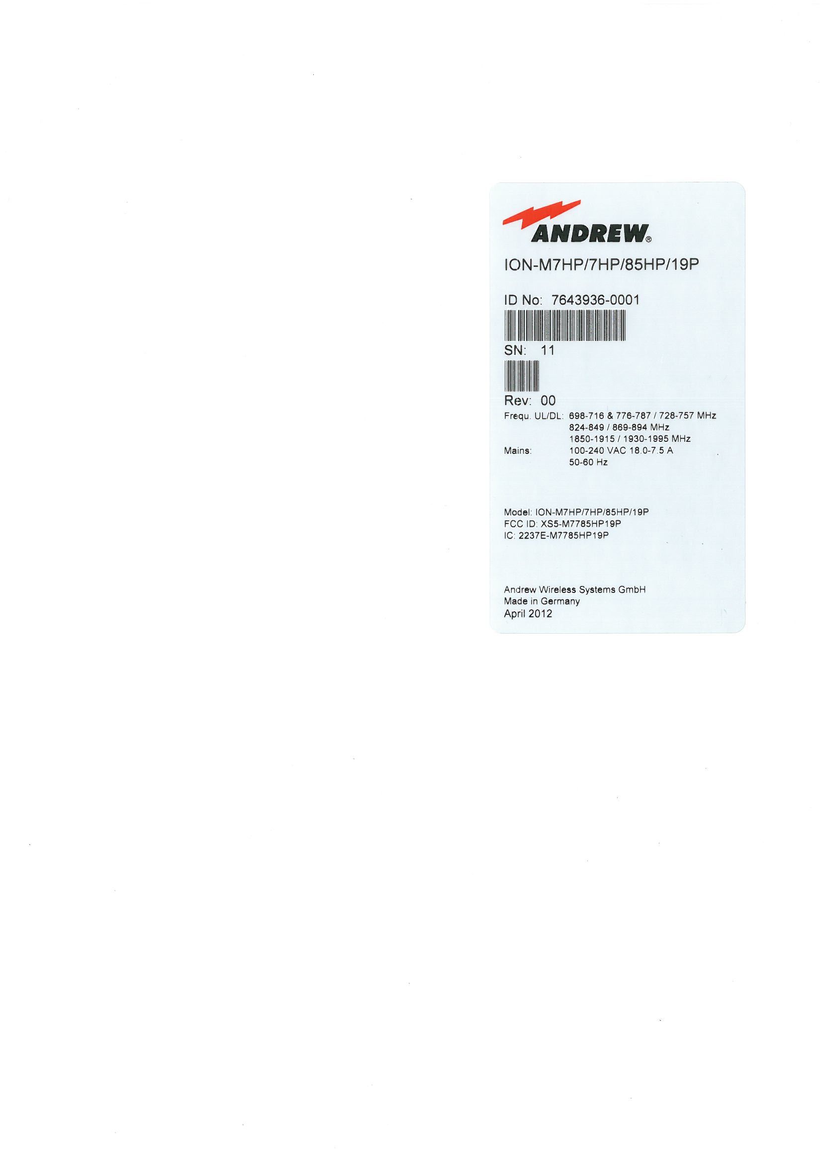
ID Label/Location Info
Label Location 6,5cm 11,5cm
Internal Photos
Internal Photos OTRX 70-85/90/17-21 RU-LS Amplifier Fin.Ampl. 1930-1995MHz Fin.Ampl. 851-894MHz Fin Ampl. 716-775MHz Frequenz Conversion Modul 7P/7P PCB P3348 Two Core Board PCB P3129 RCM161 PCB P3512 eCPD PCB P3349 Distribution Board
RF Exposure Info
RF Exposure Info / MPE Sample Calculation Model: ION‐M7HP/7HP/85HP/19P FCC‐ID: XS5‐M7785HP19P The ION‐M7HP/7HP/85HP/19P is an LTE MIMO, 850 MHz, and 1900 MHz CDMA/WCDMA multi‐operator Remote Unit. It is used in conjunction with a Master Unit in the ION optical distribution system. This system transports LTE channels, and CDMA 850 MHz; and 1900 MHz signals simultaneously, providing a cost‐effective solution for distributing capacity from one or more base stations. The ION‐M7HP/7HP/85HP/19P transports signals on the RF layer in a very inexpensive manner. This means that multiple operators and multiple technologies are moved simultaneously from a cluster of base stations to a remote location over the same fiber. The ION optical distribution system is a cost‐effective coverage solution for dense urban areas, tunnels, subway, airports, convention centers, high‐rise buildings and other locations where physical structures increase path loss. It has been specifically designed to reduce zoning problems and to provide homogeneous coverage. The compact, mechanical design is specifically architected to mount along side structures in such a way that it has a minimal visual impact. The ION is easily set‐up and supervised via a graphical user interface (GUI). Remote units can be commissioned through the use of built‐in test equipment. An auto‐leveling function compensates for the optical link loss making installation easy and quick. The entire system may be monitored remotely via an Andrew OMC. This platform uses SNMP protocol and is compliant to X.733 standard. Should a sophisticated interface not be required, the master unit can be directly connected to the alarm interface of a base station via its contact relay. The specific device generally will be professionally installed. Hereby the gain of the finally installed antenna(s), cable attenuation and antenna height will be defined site specific at the time of licensing with the appropriate FCC Bureau(s). The maximum permissible exposure limit is defined in 47 CFR 1.1310 (B). S = power density limit [W/m] P = power [W] R = distance [m] 2 4 n nn n R GP S => n nn n S GP R 4 (to calculate the distance at one frequency) If we have more bands, than we have to calculated as a percentage: The additional of the terms have to be lower than 1. 1 4 .... 4 44 1.... 2 3 2 3 33 2 2 2 22 1 2 1 11 ln 3 3 2 2 1 1 n n nn n cacalcalcal S R GP S R GP S R GP S R GP S S S S S S S S We are looking for a distance of ensures that the formula is satisfied. n RRRR... 321 1 4 ... 444 2 3 2 33 2 2 22 1 2 11 n nn SR GP SR GP SR GP SR GP R S GP S GP S GP S GP R S GP S GP S GP S GP n nn n nn 4 ... 444 4 ... 444 3 33 2 22 1 11 2 3 33 2 22 1 11 With n nn n S GP R 4 => n nn n S GP R 4 2 RRRRR n 22 3 2 2 2 1 ... What you have to do for calculate the minimum distance were the power density limit is met: 1) If you have one path, you have to put you special values in the following formula. n nn n S GP R 4 (Distance for one carrier) Limits for General Population / Uncontrolled Exposures Frequency Range (MHz) Power Density (mW/cm 2 ) 300 – 1500 S = f/1500 1550 – 100,000 S = 1 2) If you have more than one path , you must add the individual terms quadratic. n nn n S GP R 4 (Distance for individual carrier) RRRRR n 22 3 2 2 2 1 ... (See previous page) For example: The EUT operates with 4 frequency bands: Calculation with maximum possible antenna gain and without cable loss (worst case): Frequency [MHz] Max Power out [dBm] Max. possible Antenna gain, without cable loss [dBi] Max. Distance [m] 728 45.5 16.65 5.1865 746 45.5 16.65 5.1236 851 45.5 13.65 3.3961 1930 42.5 19.65 3.6132 R min > 8.817 m For more accurate calculation, the cable loss and actual antenna gain have to be included in the finally system. The antenna(s) used with device must be fixed‐mounted on permanent structures with a distance to any human body to comply with the RF Exposure limit.
Test Report
Test Site: FCC Test Site No.: 96997 IC OATS No.: IC3475A-1 The test report shall not be reproduced except in full without the written approval of the testing laboratory. ECL-EMC-TR-12-088-V01.00 Page 1 of 47 Date of issue: 16.05.12 Signature: Issue-No.: 01 Author: Date of delivery: 08.05.12 Checked: Test dates: 09.05. – 10.05.12 Pages: 47 ECL-EMC Test Report No.: 12-088 Equipment under test: ION-M7HP/7HP/85HP/19P 700MHz Path FCC ID: XS5-M7785HP19P IC ID: 2237E-M7785HP19P Type of test: FCC 47 CFR Part 27 Subpart H, F: 2011 Miscellaneous Wireless Communication Services IC RSS-131:2003 Zone Enhancers for the Land Mobile Service Measurement Procedures: 47 CFR Parts 2: 2011 (Frequency Allocations and Radio Treaty Matters; General Rules and Regulations), Part 27: 2011 (Miscellaneous Wireless Communication Services), ANSI/TIA-603-C:2004, Land Mobile FM or PM Communications Equipment Measurement and Performance Standards IC RSS-GEN:2010 General Requirements and Information for the Certification of Radiocommunication Equipment Test result: Passed Test Report No.: 12-088 FCC ID: XS5-M7785HP19P IC ID: 2237E-M7785HP19P The test report shall not be reproduced except in full without the written approval of the testing laboratory. ECL-EMC-TR-12-088-V01.00 Page 2 of 47 Manufacturer: ANDREW Wireless Systems GmbH Industriering 10 D-86675 Buchdorf Tel.: +49 (0)9099 69 0 Fax: +49 (0)9099 69 140 Test Location: TEMPTON Service Plus GmbH European Compliance Laboratory (ECL) Thurn-und-Taxis-Straße 18 D-90411 Nürnberg Tel.: +49 (0) 911 59835 0 Fax: +49 (0) 911 59835 90 General: The purpose of this report is to show compliance to the FCC regulations for devices operating under Part 27 of the Code of Federal Regulations title 47. This report informs about the results of the EMC tests, it only refers to the equipment under test. No part of this report may be reproduced in any form, without written permission. Test Report No.: 12-088 FCC ID: XS5-M7785HP19P IC ID: 2237E-M7785HP19P The test report shall not be reproduced except in full without the written approval of the testing laboratory. ECL-EMC-TR-12-088-V01.00 Page 3 of 47 Table of contents 1 TEST RESULTS SUMMARY .................................................................................................................6 2 EQUIPMENT UNDER TEST (E.U.T.) ....................................................................................................7 2.1 DESCRIPTION....................................................................................................................................7 2.1.1 DOWNLINK.................................................................................................................................7 2.1.2 UPLINK......................................................................................................................................7 2.1.3 DESCRIPTION OF EUT ................................................................................................................7 2.1.4 BLOCK DIAGRAM OF MEASUREMENT REFERENCE POINTS..............................................................8 2.1.5 DOWNLINK SYSTEM GAIN AND OUTPUT POWER...........................................................................8 3 TEST SITE (ANDREW BUCHDORF) ....................................................................................................9 3.1 TEST ENVIRONMENT..........................................................................................................................9 3.2 TEST EQUIPMENT..............................................................................................................................9 3.3 INPUT AND OUTPUT LOSSES...............................................................................................................9 3.4 MEASUREMENT UNCERTAINTY..........................................................................................................10 4 TEST SITE (TEMPTON) ......................................................................................................................11 5 RF POWER OUT: §27.50, §2.1046 .....................................................................................................12 5.1 LIMIT...............................................................................................................................................12 5.2 TEST METHOD.................................................................................................................................12 5.3 TEST RESULTS................................................................................................................................13 5.3.1 DOWNLINK...............................................................................................................................13 5.3.1.1 LTE 728 – 746MHz.........................................................................................................14 5.3.1.2 LTE 746 – 757MHz.........................................................................................................14 5.3.2 UPLINK....................................................................................................................................15 5.4 SUMMARY TEST RESULT...................................................................................................................15 6 OCCUPIED BANDWIDTH: §90.210, §2.1049.....................................................................................16 6.1 LIMIT...............................................................................................................................................16 6.2 TEST METHOD.................................................................................................................................16 6.3 TEST RESULTS................................................................................................................................16 6.3.1 DOWNLINK................................................…
Text truncated - open the document above for the full version.
Test Report
Test Site: FCC Test Site No.: 96997 IC OATS No.: IC3475A-1 The test report shall not be reproduced except in full without the written approval of the testing laboratory. ECL-EMC-TR-12-089-V01.00 Page 1 of 59 Date of issue: 16.05.12 Signature: Issue-No.: 01 Author: Date of delivery: 08.05.12 Checked: Test dates: 09.05. – 10.05.12 Pages: 59 ECL-EMC Test Report No.: 12-089 Equipment under test: ION-M7HP/7HP/85HP/19P 850MHz Path FCC ID: XS5-M7785HP19P IC ID: 2237E-M7785HP19P Type of test: FCC 47 CFR Part 22 Subpart H:2009 Cellular Radiotelephone Service IC RSS-131:2003 Zone Enhancers for the Land Mobile Service Measurement Procedures: 47 CFR Parts 2: 2011 (Frequency Allocations and Radio Treaty Matters; General Rules and Regulations), Part 22: 2011 (Cellular Radiotelephone Service), ANSI/TIA-603-C (2004), Land Mobile FM or PM Communications Equipment Measurement and Performance Standards IC RSS-GEN: 2010 General Requirements and Information for the Certification of Radiocommunication Equipment Test result: Passed Test Report No.: 12-089 FCC ID: XS5-M7785HP19P IC ID: 2237E-M7785HP19P The test report shall not be reproduced except in full without the written approval of the testing laboratory. ECL-EMC-TR-12-089-V01.00 Page 2 of 59 Manufacturer: ANDREW Wireless Systems GmbH Industriering 10 D-86675 Buchdorf Tel.: +49 (0)9099 69 0 Fax: +49 (0)9099 69 140 Test Location: TEMPTON Service Plus GmbH European Compliance Laboratory (ECL) Thurn-und-Taxis-Straße 18 D-90411 Nürnberg Tel.: +49 0911 59835 0 Fax: +49 0911 59835 90 General: The purpose of this report is to show compliance to the FCC regulations for licensed devices operating under section 22 of the Code of Federal Regulations title 47. This report informs about the results of the RF tests, it only refers to the equipment under test. No part of this report may be reproduced in any form, without written permission. Test Report No.: 12-089 FCC ID: XS5-M7785HP19P IC ID: 2237E-M7785HP19P The test report shall not be reproduced except in full without the written approval of the testing laboratory. ECL-EMC-TR-12-089-V01.00 Page 3 of 59 Table of contents 1 TEST RESULTS SUMMARY .................................................................................................................6 2 EQUIPMENT UNDER TEST (E.U.T.) ....................................................................................................7 2.1 DESCRIPTION....................................................................................................................................7 2.1.1 DOWNLINK.................................................................................................................................7 2.1.2 UPLINK......................................................................................................................................7 2.1.3 DESCRIPTION OF EUT ................................................................................................................8 2.1.4 BLOCK DIAGRAM OF MEASUREMENT REFERENCE POINTS..............................................................8 2.1.5 DOWNLINK SYSTEM GAIN AND OUTPUT POWER...........................................................................9 3 TEST SITE (ANDREW BUCHDORF) ....................................................................................................9 3.1 TEST ENVIRONMENT..........................................................................................................................9 3.2 TEST EQUIPMENT............................................................................................................................10 3.3 INPUT AND OUTPUT LOSSES.............................................................................................................10 3.4 MEASUREMENT UNCERTAINTY..........................................................................................................10 4 TEST SITE (TEMPTON SERVICE PLUS GMBH) ...............................................................................11 5 RF POWER OUT: §22.913, §2.1046; IC RSS-131 ..............................................................................12 5.1 LIMIT...............................................................................................................................................12 5.2 TEST METHOD.................................................................................................................................12 5.3 TEST RESULTS................................................................................................................................13 5.3.1 DOWNLINK...............................................................................................................................14 5.3.1.1 Analog.............................................................................................................................15 5.3.1.2 GSM................................................................................................................................15 5.3.1.3 EDGE..............................................................................................................................16 5.3.1.4 CDMA .............................................................................................................................16 5.3.1.5 WCDMA..........................................................................................................................17 5.3.1.6 LTE .................................................................................................................................17 5.3.2 UPLINK....................................................................................................................................18 5.4 SUMMARY TEST RESULT...................................................................................................................18 6 OCCUPIED BANDWIDTH: §2.1049; RSS-GEN .......................................................................…
Text truncated - open the document above for the full version.
Test Report
Test Site: FCC Test Site No.: 96997 IC OATS No.: IC3475A-1 The test report shall not be reproduced except in full without the written approval of the testing laboratory. ECL-EMC-TR-12-090-V01.00 Page 1 of 53 Date of issue: 16.05.12 Signature: Issue-No.: 01 Author: Date of delivery: 09.05.12 Checked: Test dates: 08.05. – 10.05.12 Pages: 53 ECL-EMC Test Report No.: 12-090 Equipment under test: ION-M7HP/7HP/85HP/19P 1900MHz Path FCC ID: XS5-M7785HP19P IC ID: 2237E-M7785HP19P Type of test: FCC 47 CFR Part 24 Subpart E: 2011 Broadband PCS IC RSS-131:2003 Zone Enhancers for the Land Mobile Service Measurement Procedures: 47 CFR Parts 2: 2011(Frequency Allocations and Radio Treaty Matters; General Rules and Regulations), 24 (Broadband PCS), ANSI/TIA-603-C (2004), Land Mobile FM or PM Communications Equipment Measurement and Performance Standards IC-GEN General Requirements and Information for the Certification of Radiocommunication Equipment Test result: Passed Test Report No.: 12-090 FCC ID: XS5-M7785HP19P IC ID: 2237E-M7785HP19P The test report shall not be reproduced except in full without the written approval of the testing laboratory. ECL-EMC-TR-12-090-V01.00 Page 2 of 53 Manufacturer: ANDREW Wireless Systems GmbH Industriering 10 D-86675 Buchdorf Tel.: +49 (0)9099 69 0 Fax: +49 (0)9099 69 140 Test Location: TEMPTON Service Plus GmbH European Compliance Laboratory (ECL) Thurn-und Taxis-Straße 18 D-90411 Nürnberg Tel.: +49 0911 59835 23 Fax: +49 0911 59835 90 General: The purpose of this report is to show compliance to the FCC regulations for unlicensed devices operating under section 15.249 of the Code of Federal Regulations title 47. This report informs about the results of the EMC tests, it on…
Text truncated - open the document above for the full version.
Contact Information
Applicant
Jiri Cecka(Manager Quality)
Test Firm
Bureau Veritas Consumer Products Services GermanyMario Lehmann
Technical Specifications
| # | Rule Parts | Frequency Range | Power Output | Emission | Tolerance |
|---|---|---|---|---|---|
| 4 | 24E | 1.93 GHz - 2.00 GHz | 17.8 W | NOTE 2 | Amp |
Other Applications from Andrew Wireless System

XS5-H23437HP
Apr 10, 2026CAP H2 34T/37T F-AC-F1, CAP H2 34T/37T F-DC-F1
Equipment Class
B2I - Part 20 Industrial Booster (CMRS)
XS5-CAPM2343737
Dec 14, 2023Era Repeater for cellular systems
Equipment Class
B2I - Part 20 Industrial Booster (CMRS)
XS5-RML2BDOD
Oct 25, 2023ERA L2 Radio Module
Equipment Class
B2I - Part 20 Industrial Booster (CMRS)
XS5-CAPL2CBAND
Dec 14, 2022Era Repeater for cellular systems (DAS - Remote Unit)
Equipment Class
B2I - Part 20 Industrial Booster (CMRS)
XS5-RML2B25
Sep 28, 2022ERA L2 Radio Module
Equipment Class
B2I - Part 20 Industrial Booster (CMRS)