XS5-TFAHES78ION-B Remote Unit for cellular systems
Andrew Wireless System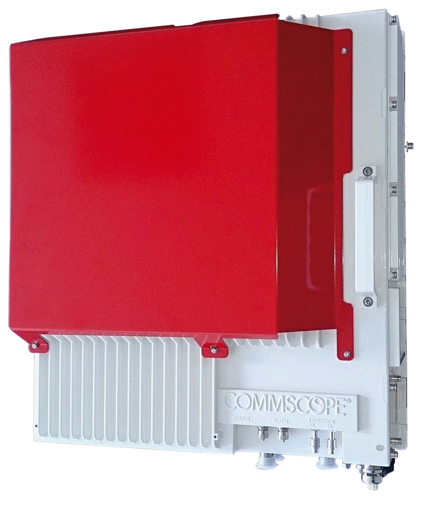
Click to zoom
Application Details
- Equipment Class
- B2I - Part 20 Industrial Booster (CMRS)
- Date of Grant
- Jun 28, 2015
- Application Purpose
- Original Equipment
- Date of Application
- Feb 11, 2015
- Equipment Note
- ION-B Remote Unit for cellular systems
- Frequency Range
- 862.00000000 - 869.00000000
- Company
- Andrew Wireless System
- Country
- Germany
Documents & Files
Document Text
Text extracted from the exhibit documents filed with the FCC. Open a document above to read the original.
Users Manual
Page 1 Manual for TFAH-ES70/80/50 and TFAH-ES70/80 MN024-15 User’s Manual for ION-B Systems Page 2 Manual TFAH- ES70_80_50.doc DISCLAIMER: This document has been developed by CommScope, and is intended for the use of its customers and customer support personnel. The information in this document is subject to change without notice. While every effort has been made to eliminate errors, CommScope disclaims liability for any difficulties arising from the interpretation of the information contained herein. The information contained herein does not claim to cover all details or variations in equipment, nor to provide for every possible incident to be met in connection with installation, operation, or maintenance. This document describes the performance of the product under the defined operational conditions and does not cover the performance under adverse or disturbed conditions. Should further information be desired, or should particular problems arise which are not covered sufficiently for the purchaser’s purposes, contact CommScope. CommScope reserves the right to change all hardware and software characteristics without notice. COPYRIGHT: © Copyright 2013 CommScope Inc. All Rights Reserved. This document is protected by copyright. No part of this document may be reproduced, stored in a retrieval system, or transmitted, in any form or by any means, electronic, mechanical photocopying, recording, or otherwise without the prior written permission of CommScope. TRADEMARKS All trademarks identified by ® or ™ are registered trademarks or trademarks, respectively, of CommScope. Names of products mentioned herein are used for identification purposes only and may be trademarks and / or registered trademarks of their respective companies. Andrew Wireless Systems GmbH, 12-December-2013 Page 3 TABLE OF CONTENTS 1.1. About CommScope 5 1.2. International Contact Addresses for Customer Support 6 2.1. Case U Remote Unit 9 2.1.1. Specifications 9 2.1.2. Health and Safety 12 2.1.3. TFAx Case U Mechanical Installation 15 2.1.4. Wall Mounting Procedure 18 2.1.5. TFAx Case U Electrical Installation 21 2.1.5.1. General 21 2.1.5.2. Grounding (Earthing) 22 2.1.5.3. Mains Power Connection 23 2.1.5.4. Antenna Connection 26 2.1.5.5. Alarm Ports 28 2.2. Low Power RU Optical Installation 29 2.2.1. Optical-Fiber-Cable Connection - Rules 29 2.2.2. Optical cable installation 31 2.2.3. RU Power Supply Replacement 34 3. TECHNICAL SUPPORT 38 3.1. Contact Addresses 38 3.2. Returning Equipment 39 User’s Manual for ION-B Systems Page 4 Manual TFAH- ES70_80_50.doc FIGURES AND TABLES Figure 4-58 Case U Remote Unit ............................................................................................. 9 Figure 4-59 Case U connectors ............................................................................................. 10 Figure 4-60 Wall-mounting bracket ........................................................................................ 16 Figure 4-61 RU threaded pin power supply side .................................................................... 17 Figure 4-62 RU threaded pin narrow side .............................................................................. 17 Figure 4-63 Place RU onto wall mounting bracket ................................................................. 18 Figure 4-64 Install M6x12 screws and washers for single mount ........................................... 19 Figure 4-65 Attach M6 nut to threaded pins for single mount ................................................ 19 Figure 4-66 Completed RU Mount ......................................................................................... 20 Figure 4-67 Grounding bolts ................................................................................................... 22 Figure 4-68 Grounding bolt, schematic view .......................................................................... 22 Figure 4-69 AC power cable ................................................................................................... 23 Figure 4-70 DC power cable .................................................................................................. 23 Figure 4-71 Vdc/100 power cable .......................................................................................... 24 Figure 4-72 Connect Mains plug ............................................................................................ 25 Figure 4-73 N-type antenna connection ................................................................................. 27 Figure 4-74 Alarm Connector ................................................................................................. 28 Figure 4-75 Remove optics cover .......................................................................................... 31 Figure 4-76 Remove sealing nut ............................................................................................ 31 Figure 4-77 Split-seal and clamp jacket ................................................................................. 32 Figure 4-78 Optical cables connected .................................................................................... 32 Figure 4-79 Place cables into split-seal .................................................................................. 33 Figure 4-80 Optical cable installed ......................................................................................... 33 Figure 4-81 Disconnect Mains power ..................................................................................... 34 Figure 4-82 RU power supply location ................................................................................... 34 Figure 4-83 8 RU power supply screws ................................................................................. 35 Figure 4-84 RU power supply with cables .............................................................................. 35 Figure 4-85 RU power supply input cable .......................…
Text truncated - open the document above for the full version.
Users Manual
Installation Instruction The Remote Unit, Extension Unit or Master Unit has to be mounted by proffessionel / special trained installer. 1.1. TFAX CASE U MECHANICAL INSTALLATION 1.1.1. General Read the health and safety warnings in chapter 1.3. 1. Warning: Do not install the unit in a way or at a place where the specifications outlined in the Environmental and Safety Specifications leaflet of the supplier are not met. 2. WARNING: IMPROPER INSTALLATION CAN LEAD TO EQUIPMENT FALLING CAUSING SERIOUS PERSONAL INJURY OR DAMAGE TO EQUIPMENT. The installer must verify that the supporting surface will safely support the combined load of the electronic equipment and all attached hardware and components. The screws and dowels (wall anchors) used should also be appropriate for the structure of the supporting wall. 3. Warning: It is recommended to use the mounting hardware delivered by the manufacturer only. If different mounting hardware is used, the specifications for stationary use of the Remote Unit must not be exceeded. 4. Note: Exceeding the specified load limits may cause the loss of warranty! 5. Warning: The unit is considerably heavy. Ensure there is adequate manpower to handle the weight of the system. 6. Caution: Due to power dissipation, the Remote Unit may reach a very high temperature. Ensure sufficient airflow for ventilation. 7. Note: When connecting and mounting the cables (RF, optical, mains, ...) ensure that no water can penetrate into the unit through these cables. 8. Note: Observe all additional rules or restrictions regarding mounting that apply to specific Remote Unit types. If any different or additional mounting material is used, ensure that the mounting remains as safe as the mounting designed by the manufacturer. Ensure that the static and dynamic strengths are adequate for the environmental conditions of the site. The mounting itself must not vibrate, swing or move in any way that might cause damage to the Remote Unit. Specified torques must be observed for certain mounting procedures according to the following table: Type Pins Hex nuts Screws Thread M 6 M 6 M6 Specified torques 3.3 Nm 3.3 Nm 3.3 Nm 1.2. TFAX CASE U ELECTRICAL INSTALLATION 1.2.1. General Read the health and safety warnings in chapter 1.3. 1. Warning: This unit contains dangerous voltages. Loss of life, severe personal injury, or property damage can be the result if the instructions contained in this manual are not followed. 2. Caution: It is compulsory to ground (earth) the unit before connecting the power supply. A grounding bolt is provided on the cabinet to connect the ground-bonding cable. 3. Caution: Although the remote unit is internally protected against overvoltage, it is strongly recommended to ground (earth) the antenna cables close to the antenna connectors of the remote unit for protection against atmospheric discharge. In areas with strong lightning, it is strongly recommended to install additional lightning protection. 4. Caution: If the mains connector of the remote unit is not easily accessible, a disconnect device in the mains power circuit must be provided within easy reach. 5. Caution: Before connecting or disconnecting the mains connector at the remote unit, ensure that mains power supply is disconnected. 6. Caution: Make sure that an appropriate circuit breaker acting as a disconnect device (as required by IEC/EN60950-1) and an overcurrent limiting device are connected between mains power and the Remote Unit. 7. Caution: A connection of the mains supply to a power socket requires the power socket to be nearby the remote unit. 8. Caution: Incorrectly wired connections can destroy electrical and electronic components. 9. Caution: To avoid corrosion at the connectors caused by electrochemical processes, the material of the cable connectors must not cause a higher potential difference than 0.6 V (see electrochemical contact series). 10. Note: Use an appropriate torque wrench for the coupling torque of N-type connectors (2 Nm / 1.5 lb/ft), with 13/16 in opening to tighten the N-type antenna connectors. For example, use torque wrench of item no. 244379 available from the CommScope e-catalog. Do NOT use your hands or any other tool (e.g. a pair of pliers)! This might cause damage to the connector and lead to a malfunction of the Remote Unit. 11. Caution: For unstabilized electric networks, which frequently generate spikes, the use of a voltage limiting device is advised. 12. Caution: The unit complies with the surge requirement according to EN 61000-4-5 (fine protection); however, installation of an additional medium (via local supply connection) and/or coarse protection (external surge protection) is recommended depending on the individual application in order to avoid damage caused by overcurrent. 13. Caution: Observe the labels on the front panels before connecting or disconnecting any cables. 1.3. HEALTH AND SAFETY WARNINGS 1. Danger: Obey all general and regional installation and safety regulations relating to work on high voltage installations, as well as regulations covering correct use of tools and personal protective equipment. 2. Danger: Before opening the unit, disconnect mains power. 3. Danger: Laser radiation! Do not stare into the beam; do not view it directly or with optical instruments. 4. Danger: Due to power dissipation, the remote unit may reach a very high temperature. Do not operate this equipment on or close to flammable materials. Use caution when servicing the unit. 5. Warning: Read and obey all the warning labels attached to the unit. Make sure that all warning labels are kept in a legible condition. Replace any missing or damaged labels. 6. Warning: It is the responsibility of the network provider to implement prevention measures to avoid health hazards associated with radiation from the antenna(s) connected to the unit. 7. Warning: Only authorized and trained personnel are allowed to open the unit and get access to the inside. 8. Warning: Only license holders for …
Text truncated - open the document above for the full version.
Users Manual
Page 1 Manual for TFAH-ES70/80/50 and TFAH-ES70/80 MN024-15 User’s Manual for ION-B Systems Page 2 Manual TFAH- ES70_80_50.doc DISCLAIMER: This document has been developed by CommScope, and is intended for the use of its customers and customer support personnel. The information in this document is subject to change without notice. While every effort has been made to eliminate errors, CommScope disclaims liability for any difficulties arising from the interpretation of the information contained herein. The information contained herein does not claim to cover all details or variations in equipment, nor to provide for every possible incident to be met in connection with installation, operation, or maintenance. This document describes the performance of the product under the defined operational conditions and does not cover the performance under adverse or disturbed conditions. Should further information be desired, or should particular problems arise which are not covered sufficiently for the purchaser’s purposes, contact CommScope. CommScope reserves the right to change all hardware and software characteristics without notice. COPYRIGHT: © Copyright 2015 CommScope Inc. All Rights Reserved. This document is protected by copyright. No part of this document may be reproduced, stored in a retrieval system, or transmitted, in any form or by any means, electronic, mechanical photocopying, recording, or otherwise without the prior written permission of CommScope. TRADEMARKS All trademarks identified by ® or ™ are registered trademarks or trademarks, respectively, of CommScope. Names of products mentioned herein are used for identification purposes only and may be trademarks and / or registered trademarks of their respective companies. Andrew Wireless Systems GmbH, 02-April-2015 Page 3 TABLE OF CONTENTS 1.1. About CommScope 4 1.2. International Contact Addresses for Customer Support 5 2. GENERAL INTRODUCTION OF ION-B PRODUCTS 7 2.1. THE FEATURES 7 2.2. BRIEF DESCRIPTION OF ION-B 7 2.3. ION-B FEATURES 8 2.4. TYPICAL ION-B APPLICATIONS 9 2.5. THE ION-B REMOTE UNIT AND ITS RELEVANT ACCESSORIES 10 3. TFAH-ES70/80/50 & TFAH-ES70/80 11 3.1. Case U Remote Unit 11 3.1.1. Specifications 11 3.1.2. Health and Safety 14 3.1.3. TFAx Case U Mechanical Installation 17 3.1.4. Wall Mounting Procedure 20 3.1.5. TFAx Case U Electrical Installation 23 3.1.5.1. General 23 3.1.5.2. Grounding (Earthing) 25 3.1.5.3. Mains Power Connection 26 3.1.5.4. Antenna Connection 29 3.1.5.5. Alarm Ports 30 3.2. Low Power RU Optical Installation 31 3.2.1. Optical-Fiber-Cable Connection - Rules 31 3.2.2. Optical cable installation 33 3.2.3. RU Power Supply Replacement 36 4. TECHNICAL SUPPORT 40 4.1. Contact Addresses 40 4.2. Returning Equipment 41 User’s Manual for ION-B Systems Page 4 Manual TFAH- ES70_80_50.doc 1.1. ABOUT COMMSCOPE CommScope is the foremost supplier of one-stop, end-to-end radio frequency (RF) solutions. Part of the CommScope portfolio are complete solutions for wireless infrastructure from top-of-the-tower base station antennas to cable systems and cabinets, RF site solutions, signal distribution, and network optimization. CommScope has global engineering and manufacturing facilities. In addition, it maintains field engineering offices throughout the world. Andrew Wireless Systems GmbH based in Buchdorf/ Germany, which is part of CommScope, is a leading manufacturer of coverage equipment for mobile radio networks, specializing in high performance, RF and optical repeaters. Our optical distributed networks and RF repeater systems provide coverage and capacity solution for wireless networks in both indoor installations and outdoor environments, e.g. tunnels, subways, in-trains, airport buildings, stadiums, skyscrapers, shopping malls, hotels and conference rooms. Andrew Wireless Systems GmbH operates a quality management system in compliance with the requirements of ISO 9001 and TL 9000. All equipment is manufactured using highly reliable material. To maintain highest quality of the products, comprehensive quality monitoring is conducted at all fabrication stages. Finished products leave the factory only after a thorough final acceptance test, accompanied by a test certificate guaranteeing optimal operation. This product meets the requirements of the R&TTE directive and the Declaration of Conformity (DoC) itself. A current version of the CE DoC is included in this manual CD delivered *. Any updated version of the DoC is available upon request from the local sales offices or directly from CommScope via the local Customer Support at one of the addresses listed in the following chapter. According to the DoC, our "CE"-marked equipment can be used in all member states of the European Union. F Note: Exceptions of and national deviations from this intended use may be possible. To observe corresponding local particularities and regulations, please refer to the respective documents (also in national language) which are included in the manual CD delivered. * In case the Declaration of Conformity (DoC) for the product was not included in the manual CD delivered, it is available upon request from the local sales offices or directly from CommScope at one of the addresses listed in the following chapter. To make the most of this product, we recommend you carefully read the instructions in this manual and commission the system only according to these instructions. For technical assistance and support, please also contact the local office or CommScope directly at one of the addresses listed in the following chapter. User’s Manual for ION-B Systems Page 5 1.2. INTERNATIONAL CONTACT ADDRESSES FOR CUSTOMER SUPPORT Canada A M E R I C A S United States CommScope Canada Andrew LLC, A CommScope Company Mail 505 Consumers Road, Suite 803 Toronto M2J 4V8, Canada Mail 620 North Greenfield Parkway Garner, NC 27529, U.S.A. Phone +1-905-878-3457 (Office) +1-416-721-5058 (Cell) Phone +1-888-297-6433 Fax +1-905-878-3297 Fax +1-919-329-8950 E-mail…
Text truncated - open the document above for the full version.
External Photos
External Photos TFAH-ES70/80-17
ID Label/Location Info
Label Location 5cm 6,5cm
ID Label/Location Info
65 35 5.5 3 21.5 26.5 32 29.7 18.5 Lettering FCC no harmonised frequency bands, operation needs license. Print: black, alcohol resistant. Material: 3M 7879EJ-3M TT3 MS PET 75-350E/46-90DWG For RoHS Inquiries: CommScope Inc. Corke Abbey, Bray. Co. Dublin, Ireland. Attn: Legal Department Unauthorized use may result in significant forfeiture penalties, For Patents See www.CS-pat.com including penalties in excess of $100,000 for each continuing violation. WARNING. This is NOT a CONSUMER device. It is designed for installation by FCC LICENSEES and QUALIFIED INSTALLERS. You MUST have an FCC LICENSE or express consent of an FCC Licensee to operate this device. To be sold exclusively to mobile operators or authorized installers, ID: 7677269-00 hwi D E F C 1234 B A 3215 C D 4678 A B 0 100 This drawing is property of Andrew Wireless Systems GmbH, Buchdorf. It may not be copied or exhibited without written permissio n. FIRST ANGLE PROJECTION FIRST ANGLE PROJECTION 7677269-00 1:1 hwi 03 VERSION RE STATUS D VERSION STATUS REVISION MODELDRAWING SW Finish ToleranceSAP Material Master Name Date Modification Cond. Prod. APP. OriginRepl. forRepl. by REVISION Industriering 10, 86675 Buchdorf R 1 Shts. Andrew Wireless Systems GmbH 1 DRW. CHK. NAME DATE MATERIAL: TITLE: Drawing-No. SCALE A3 G3300A320 Accreditation Label, silver ECN: 000007016504 AUTH. GROUP: 70 CAGE CODE 84147 ±2 HEWIEDERMAN12/22/2014 12/22/2014 HEWIEDERMAN 12/22/2014 12/22/2014 MASTRASSNER HEWIEDERMAN B C D 7016504 A705969 add sign 22.12.14 21.2.14 24.10.13 Sheet hwi
Internal Photos
Internal Photos TFAH-ES 70/80-17 Duplexer Power Supply Optical Module Amplification Part for 70/80 and optical module Optical Module Part 70/80 PCB P3825 Interface Board
RF Exposure Info
RF Exposure Info / MPE Sample Calculation Model: TFAH-ES70/80 FCC-ID: XS5-TFAHES78 The Andrew Intelligent Optical Network (ION) Series is the industry-leading optical distribution system that covers the full range of power levels, sending signals loss-free at distances ranging from 100 m to 20 km. ION-B Series provides optimized multi-band, multi-operator, cost effective solutions. The ION-B Series system is a Radio-over-Fiber solution able to meet any signal distribution need, from the simplest to the most demanding applications. The TFAH-ES70/80 is a dual band high power remote unit designed to distribute LMR700 and LMR800 band signals along the same fiber. RF signals are transported to the remote units via single mode fiber at 1310 nm. The remote unit can be placed up to 3 km (about 2 miles) from the master unit side. The system includes an Automatic Gain Control (AGC) that avoids field adjustments and reduces design, installation and optimization time. As part of the ION-B Series the unit can be easily commissioned and supervised via a web- based Graphical User Interface (GUI). The specific device generally will be professionally installed. Hereby the gain of the finally installed antenna(s), cable attenuation and antenna height will be defined site specific at the time of licensing with the appropriate FCC Bureau(s). The maximum permissible exposure limit is defined in 47 CFR 1.1310 (B). S = power density limit [W/m] P = power [W] R = distance [m] 2 4 n nn n R GP S => n nn n S GP R 4 (to calculate the distance at one frequency) If we have more bands, than we have to calculated as a percentage: The additional of the terms have to be lower than 1. 1 4 .... 4 44 1.... 2 3 2 3 33 2 2 2 22 1 2 1 11 ln 3 3 2 2 1 1 n n nn n cacalcalcal S R GP S R GP S R GP S R GP S S S S S S S S We are looking for a distance of ensures that the formula is satisfied. n RRRR... 321 1 4 ... 444 2 3 2 33 2 2 22 1 2 11 n nn SR GP SR GP SR GP SR GP R S GP S GP S GP S GP R S GP S GP S GP S GP n nn n nn 4 ... 444 4 ... 444 3 33 2 22 1 11 2 3 33 2 22 1 11 With n nn n S GP R 4 => n nn n S GP R 4 2 RRRRR n 22 3 2 2 2 1 ... What you have to do for calculate the minimum distance were the power density limit is met: 1) If you have one path, you have to put you special values in the following formula. n nn n S GP R 4 (Distance for one carrier) Limits for General Population / Uncontrolled Exposures Frequency Range (MHz) Power Density (mW/cm 2 ) 300 – 1500 S = f/1500 1550 – 100,000 S = 1 2) If you have more than one path, you must add the individual terms quadratic. n nn n S GP R 4 (Distance for individual carrier) RRRRR n 22 3 2 2 2 1 ... (See previous page) For example: The EUT operates 4 frequency bands: Calculation for every path with maximum possible antenna gain and without cable loss: Frequency [MHz] Max Power out [dBm] f. e. Antenna gain, without cable loss [dBi] Max. Distance [m] 758 31 9 0.3968 769 31 9 0.3940 851 31 9 0.3745 862 31 9 0.3721 The worst case would be if all bands were active: RRRRR n 22 3 2 2 2 1 ... R all > 0.591 m (see previous page for formula) For more accurate calculation, the cable loss and actual antenna gain have to be included in the finally system. The antenna(s) used with device must be fixed-mounted on permanent structures with a distance to any human body to comply with the RF Exposure limit.
Test Report
Test Site: FCC Test Site No.: 96997 IC OATS No.: IC3475A-1 The test report shall not be reproduced except in full without the written approval of the testing laboratory. ECL-EMC-TR-14-204-V01.00 Page 1 of 40 Date of issue: 03.11.14 Signature: Issue-No.: 01 Author: Date of delivery: 11.08.14 Checked: Test dates: 17.02. – 12.08.14 Pages: 40 Equipment under test: TFAH-ES70/80 862MHz Path FCC ID: XS5-TFAHES78 Type of test: FCC 47 CFR Part 90 Subpart S:2014 Private Land Mobile Repeater Measurement Procedures: 47 CFR Parts 2:2014 (Frequency Allocations and Radio Treaty Matters; General Rules and Regulations), Part 90:2014 (Private Land Mobile), ANSI/TIA-603-C (2004), Land Mobile FM or PM Communications Equipment Measurement and Performance Standards Test result: Passed ECL-EMC Test Report No.: 14-204 Test Report No.: 14-204 FCC ID: XS5- TFAHES78 The test report shall not be reproduced except in full without the written approval of the testing laboratory. ECL-EMC-TR-14-204-V01.00 Page 2 of 40 General: The purpose of this report is to show compliance to the FCC regulations for licensed devices operating under section 90 of the Code of Federal Regulations title 47. This report informs about the results of the RF tests, it only refers to the equipment under test. No part of this report may be reproduced in any form, without written permission. Test Location: Bureau Veritas Consumer Products Services Germany GmbH European Compliance Laboratory (ECL) Thurn-und-Taxis-Straße 18 D-90411 Nürnberg Tel.: +49 40 74041 0 Fax: +49 40 74041-2755 Manufacturer: ANDREW Wireless Systems GmbH Industriering 10 D-86675 Buchdorf Tel.: +49 (0)9099 69 0 Fax: +49 (0)9099 69 140 Test Report No.: 14-204 FCC ID: XS5- TFAHES78 The test report shall not be reproduced except in full without the written approval of the testing laboratory. ECL-EMC-TR-14-204-V01.00 Page 3 of 40 Table of contents 1 TEST RESULTS SUMMARY ................................................................................................................. 5 2 EQUIPMENT UNDER TEST (E.U.T.) .................................................................................................... 6 2.1 DESCRIPTION .................................................................................................................................... 6 2.1.1 DOWNLINK ................................................................................................................................. 6 2.1.2 UPLINK ...................................................................................................................................... 6 2.1.3 DESCRIPTION OF EUT ................................................................................................................ 6 2.1.4 BLOCK DIAGRAM OF MEASUREMENT REFERENCE POINTS .............................................................. 7 2.1.5 DOWNLINK SYSTEM GAIN AND OUTPUT POWER ........................................................................... 7 3 TEST SITE (ANDREW BUCHDORF) .................................................................................................... 8 3.1 TEST ENVIRONMENT .......................................................................................................................... 8 3.2 TEST EQUIPMENT .............................................................................................................................. 8 3.3 INPUT AND OUTPUT LOSSES ............................................................................................................... 9 3.4 MEASUREMENT UNCERTAINTY ............................................................................................................ 9 4 TEST SITE (BUREAU VERITAS CONSUMER PRODUCTS SERVICES) ......................................... 10 5 RF POWER OUT: §90.635, §2.1046 ................................................................................................... 11 5.1 LIMIT............................................................................................................................................... 11 5.2 TEST METHOD ................................................................................................................................. 11 5.3 TEST RESULTS ................................................................................................................................ 12 5.3.1 DOWNLINK ............................................................................................................................... 13 5.3.1.1 Analog............................................................................................................................. 14 5.3.1.2 APCO Phase1 C4FM ..................................................................................................... 14 5.3.1.3 APCO Phase2 H-DQPSK ............................................................................................... 15 5.3.2 UPLINK .................................................................................................................................... 15 5.4 SUMMARY TEST RESULT ................................................................................................................... 15 6 OCCUPIED BANDWIDTH: §90.210, §2.1049 ..................................................................................... 16 6.1 LIMIT............................................................................................................................................... 16 6.2 TEST METHOD ................................................................................................................................. 16 6.3 TEST RESULTS ................................................................................................................................ 16 6.3.1 DOWNLINK ............................................................................................................................... 16 6.3.1.1 Analog.................................…
Text truncated - open the document above for the full version.
Test Report
Test Site: FCC Test Site No.: 96997 IC OATS No.: IC3475A-1 The test report shall not be reproduced except in full without the written approval of the testing laboratory. ECL-EMC-TR-14-201-V02.00 Page 1 of 36 Date of issue: 01.06.15 Signature: Issue-No.: 02 Author: Date of delivery: 11.08.14 Checked: Test dates: 18.07.14– 21.04.15 Pages: 36 Equipment under test: TFAH-ES70/80-17 700MHz Path FCC ID: XS5-TFAHES78 Type of test: FCC 47 CFR Part 90 Subpart R: 2014 Private Land Mobile Repeater Measurement Procedures: 47 CFR Parts 2: 2014 (Frequency Allocations and Radio Treaty Matters; General Rules and Regulations), Part 90:2014 (Private Land Mobile), ANSI/TIA-603-C (2004), Land Mobile FM or PM Communications Equipment Measurement and Performance Standards Test result: Passed ECL-EMC Te…
Text truncated - open the document above for the full version.
Contact Information
Applicant
Jiri Cecka(Manager Quality)
Test Firm
Bureau Veritas Consumer Products Services GermanyMario Lehmann
Technical Specifications
| # | Rule Parts | Frequency Range | Power Output | Emission | Tolerance |
|---|---|---|---|---|---|
| 3 | 90S | 862 MHz - 869 MHz | 1.26 W | D1W | Amp |
Other Applications from Andrew Wireless System

XS5-H23437HP
Apr 10, 2026CAP H2 34T/37T F-AC-F1, CAP H2 34T/37T F-DC-F1
Equipment Class
B2I - Part 20 Industrial Booster (CMRS)
XS5-CAPM2343737
Dec 14, 2023Era Repeater for cellular systems
Equipment Class
B2I - Part 20 Industrial Booster (CMRS)
XS5-RML2BDOD
Oct 25, 2023ERA L2 Radio Module
Equipment Class
B2I - Part 20 Industrial Booster (CMRS)
XS5-CAPL2CBAND
Dec 14, 2022Era Repeater for cellular systems (DAS - Remote Unit)
Equipment Class
B2I - Part 20 Industrial Booster (CMRS)
XS5-RML2B25
Sep 28, 2022ERA L2 Radio Module
Equipment Class
B2I - Part 20 Industrial Booster (CMRS)