XSG836406RF Interface and Beacon
VELUX America Inc.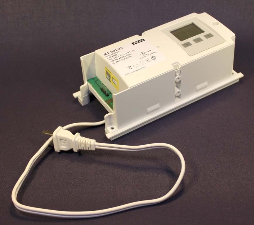
Click to zoom
Application Details
- Equipment Class
- DSS - Part 15 Spread Spectrum Transmitter
- Date of Grant
- May 14, 2010
- Application Purpose
- Original Equipment
- Date of Application
- May 14, 2010
- Equipment Note
- RF Interface and Beacon
- Frequency Range
- 2425.00000000 - 2475.00000000
- Company
- VELUX America Inc.
- Country
- United States
Documents & Files
Document Text
Text extracted from the exhibit documents filed with the FCC. Open a document above to read the original.
Users Manual
VAS 452421-2010-03 Directions for use KLF 100 ENGLISH: User manual ESPAÑOL: Manual de usario FRANÇAIS : Notice d'utilisation JAPANESE: 2 VELUXVELUX 3 English User manual x-x Español Manual del usuario x-x Français Notice d'utilisation x-x Japanese User manual x-x 4 VELUX ENGLISH VELUX 5 ENGLISH Important information 6-8 Getting started Fitting 10 Initial set-up 11 Guide to quick standard set-up 12 Example of typical use of the interface/repeater unit 13 Interface/repeater unit function and connection 14-15 Settings Channels 16-19 - Set channel 16 - Block channel 17 - Permanent blocking 18-19 Setting of position 20-21 - Position UP 21 - Position DOWN 21 System settings Register products 22-25 - From a remote control 23 - From a new product 24-25 Select products 26-27 Security key 28-29 Copy system 30-31 Signal mode 32-33 Function as repeater unit 34-35 Intelligent building installations 36 Contents ENGLISHENGLISH 7 6 VELUXVELUX 7 products connected to it (including battery backup KLB, if installed) and ensure that it cannot be reconnected unintentionally during this time. • The product requires a minimal amount of maintenance. The surface may be cleaned with a soft, damp cloth using a small amout of household cleaner diluted in water. • If main power supply cable is damaged, it must be replaced by qualified electrical installer in accordance with all local codes, ordinances, rules and regulations. • If you have any technical questions, please contact VELUX. Installation • The interface/repeater unit is for indoor use only. • Installation in rooms with a high level of humidity and with hidden wiring must comply with relevant regulations (contact a qualified electrician if necessary). Function • Check that the interface/repeater unit can operate the relevant products from the chosen position before final fixing. • If a skylight has been opened manually, it cannot be activated via the inter- face/repeater unit . • In case of snow and/or ice, the automatic operation of certain products may be blocked. • The entries in the interface/repeater unit draw 5-10 mA at approx 10 V d.c. and must be connected to potential free contacts. • Avoid frequent activation of the motors in the system from automatic sys- tems (eg IBI systems) as this will reduce the service life of the motors. • The interface/repeater unit can be used as a repeater that extends the operation range of remote controls in the system. Product • The interface/repeater unit is used when products are to be controlled with external control devices that are not compatible. ImPORtANt INFORmAtION AND WARNINGS WARNING - tO REDuCE tHE RISK OF SEvERE INJuRy OR DEAtH: Safety • Read instructions carefully before installing and operating. • Please keep instructions for future reference and hand them over to any new user. • Never let children operate or play with the system. The remote control should be kept out of reach of children at a minimum height of 5 feet. • The product must not be put into operation until it has been fitted accor- ding to these in-structions. • Before operating ensure that the product can be and is operated without risk of damage to property or injury to people or animals. • If repair and adjustment work is needed, disconnect from the main power supply and ensure that it cannot be reconnected unintentionally. • The interface/repeater unit must not be covered (maximum casing tempe- rature: 104°F/40°C). • This product has been designed for use with genuine VELUX products. Connection to or use with other products may cause damage, malfunction or injury. • The interface/repeater unit has a Class 2 Low Voltage output (19-24 V d.c.). • The power supply cable is equipped with a polarized plug. Do not change the plug. • Disconnect from the main power supply before carrying out any mainte- nance, repair, adjustment or service work to the interface/repeater unit or Important information 8 VELUX ENGLISH VELUX 9 ENGLISH • The interface/repeater unit has a built-in RF (radio frequency) unit and will not be operative if placed in a metal cabinet. • Electrical products must be disposed of in conformity with all local codes, ordinances, rules and regulations for electronic waste and not with house- hold waste. • Used remote control batteries have to be disposed of in conformity with the relevant environmental regulations and ordinances. • The packaging can be disposed of with usual household waste. • Radio frequency band: 2.4 GHz. • Radio frequency range: 110 yeards (100 m) free field. Depending on building construction, the indoor range is approx 30 ft (10 m). However, construc- tions with reinforced concrete, metal ceilings and plaster walls with steel members may reduce the range. maintenance and service • Spare parts are available through VELUX. Please provide information from the data plate. Important information 10 VELUX ENGLISH VELUX 11 ENGLISH Back INFORMATION Language saved Back INFORMATION Function saved EnterBack AB C D E F G H Dansk English Deutsch LANG uAGE EnterBack AB C D E F G H Dansk English Deutsch LANG uAGE EnterBack ABC D E F G H Interface Interface/repeater unit Reset system Fu NCTION Fitting 1 Remove cover. 2 Decide position of interface/repeater. Note: Check that the interface/re- peater unit can operate the relevant products from the chosen position before final fixing. 3 Connect interface/repeater unit to power supply. Do not replace cover until the entire installation process is completed. The display appears automatically when the mains power is switched on. After a short time menu item A is displayed. A Language 1 Press to highlight your language. Press "Enter" to confirm your choice. 2 The display shows that the language has been saved. After a short time menu item B is displayed. B Function The interface/repeater unit is used when products are to be controlled with external control devices that are not compatible, eg intelligent building installations, sensors and standard wall switches. 1 Press to highlight…
Text truncated - open the document above for the full version.
Cover Letter(s)
VELUX A/S Ådalsvej 99 DK-2970 Hørsholm Attention: Monica Roos, Intertek Application Examiner: Re: Cover Letter Applicant: VELUX America Inc. FCC ID: XSG836406 To whom it may concern, Cover Letter / Agency Letter We, VELUX A/S, hereby authorize Intertek Semko AB, Sweden, to act as agent in the preparation of this application, FCC ID: XSG836406 for equipment authorization to the Federal Communications Commission. I certify that submitted Exhibits properly describe the device with FCC ID: XSG836406 This is to advise that we are in full compliance with the Anti-Drug Abuse Act. The applicant is not subject to a denial of federal benefits pursuant to Section 5301 of the Anti-Drug Act of 1988, 21 U.S.C. 862, and no party to the application is subject to a denial of federal benefits pursuant to that section. Sincerely, Signature: Jens Philipsen Title: Approval Engineer Company: VELUX A/S
External Photos
1(1) External photos Velux 3LF S01 US
ID Label/Location Info
1(1) Label and label location Velux 3LF S01 US
Internal Photos
1(1) Internal photos Velux 3LF S01 US
Test Report
Intertek Semko AB Torshamnsgatan 43, Box 1103, SE-164 22 Kista, Sweden Telephone +46 8 750 00 00, Fax +46 8 750 60 30, www.sweden.intertek-etlsemko.com Registered in Sweden: No SE556024059901, Registered office: As address r d f n c Test report no. 917818-2 Page 2 (44) CONTENTS Page 1. Client information.............................................................................................................................3 2. Equipment under test (EUT)...........................................................................................................3 2.1 Identification of the EUT according to the manufacturer/client declaration...................3 3. Test specifications...........................................................................................................................4 3.1 Standards................................................................................................................................4 3.2 Additions, deviations and exclusions from standards.......................................................4 3.3 Test set-up..............................................................................................................................4 3.4 Operating environment..........................................................................................................4 4.Test summary....................................................................................................................................5 5.Peak output power............................................................................................................................6 5.1 Test protocol...........................................................................................................................6 6.6 dB Bandwidth.................................................................................................................................9 6.1 Test protocol...........................................................................................................................9 7.Spectral power density...................................................................................................................12 7.1 Test protocol.........................................................................................................................12 8.Band edge compliance...................................................................................................................15 8.1 Test protocol.........................................................................................................................15 9. Radiated spurious emissions.......................................................................................................17 9.1 Operating environment........................................................................................................17 9.2 Measurement uncertainty...................................................................................................17 9.3 Test equipment.....................................................................................................................17 9.4 Measurement set-up............................................................................................................18 9.5 Test protocol.........................................................................................................................20 10. Out of band spurious emissions, Conducted at antenna port...............................................32 11. 99% Bandwidth...........................................................................................................................39 11.1 Test protocol.......................................................................................................................39 12. Conducted emission from AC-mains........................................................................................42 12.1 Test protocol.......................................................................................................................42 Appendix – Photos of the EUT.........................................................................................................44 Intertek Semko AB Torshamnsgatan 43, Box 1103, SE-164 22 Kista, Sweden Telephone +46 8 750 00 00, Fax +46 8 750 60 30, www.sweden.intertek-etlsemko.com Registered in Sweden: No SE556024059901, Registered office: As address r d f n c Test report no. 917818-2 Page 3 (44) 1. CLIENT INFORMATION The EUT has been tested by request of Company: Velux A/S Aadaljsvej 99 DK-2970 Hörsholm Denmark Name of contact: Jens Philipsen 2. EQUIPMENT UNDER TEST (EUT) 2.1 Identification of the EUT according to the manufacturer/client declaration Equipment: RF Interface Beacon Type/Model: 3LF S01 US Brand name: Velux Serial number: No visible serial number on EUT Manufacturer: Velux A/S Rating/Supplying voltage: 120 V AC, 60 Hz Rating RF output power: 13 dBm Antenna gain: 2.5 dBi External antenna connector: NO Operating temperature range: 5 to 35 °C Frequency range: 2425 – 2475 MHz Number of channels: 3 Channel spacing 25 MHz Modulation characteristics: DSSS 802.15.4 Stand by mode supported: Yes Intertek Semko AB Torshamnsgatan 43, Box 1103, SE-164 22 Kista, Sweden Telephone +46 8 750 00 00, Fax +46 8 750 60 30, www.sweden.intertek-etlsemko.com Registered in Sweden: No SE556024059901, Registered office: As address r d f n c Test report no. 917818-2 Page 4 (44) 3. TEST SPECIFICATIONS 3.1 Standards FCC 47 CFR part 15 (2009) Subpart B – Unintentional radiators FCC 47 CFR part 15 (2009) Subpart C – Intentional Radiators; §15.247 Operation within the bands 902-928 MHz, 2400 – 2483.5 MHz and 5725 – 5850 MHz. Measurements methods according to ANSI C63.4-2003 - Methods of Measurements of Radio- Noise Emissions from Low-Voltage Electrical and Electronic Equipment in the Range of 9 kHz to 40 GHz RSS-Gen, Issue 2 (june 2007): General Requirements and Information f…
Text truncated - open the document above for the full version.
Test Setup Photos
1(2) Test set-up photos Velux 3LF S01 US 30 – 1000 MHz 1 – 26 GHz 2(2) Conducted emission from AC-mains
Contact Information
Applicant
Jens Aksel Thomsen(Electric safety and EMC/RF Ing.)
Technical Contact
Non-Technical Contact
VELUX A/SJens Philipsen
[email protected]+45 2343 3339
Test Firm
Intertek SEMKO ABNiklas Bostrom
Technical Specifications
| # | Rule Parts | Frequency Range | Power Output |
|---|---|---|---|
| 1 | 15C | 2.42 GHz - 2.48 GHz | 20.00 mW |
Other Applications from VELUX America Inc.
XSG866062
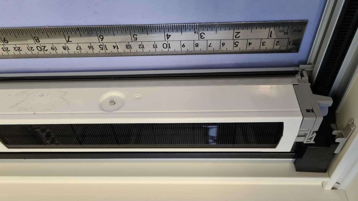
Sep 17, 2024Blind (battery powered)
Equipment Class
DTS - Digital Transmission System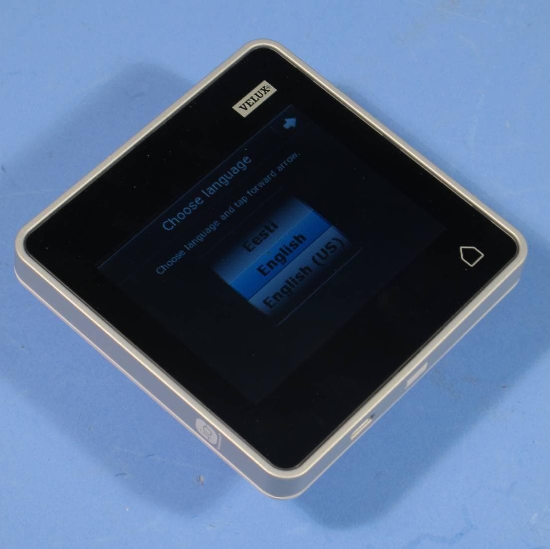
XSG835403
Aug 04, 2015Remote control
Equipment Class
DTS - Digital Transmission System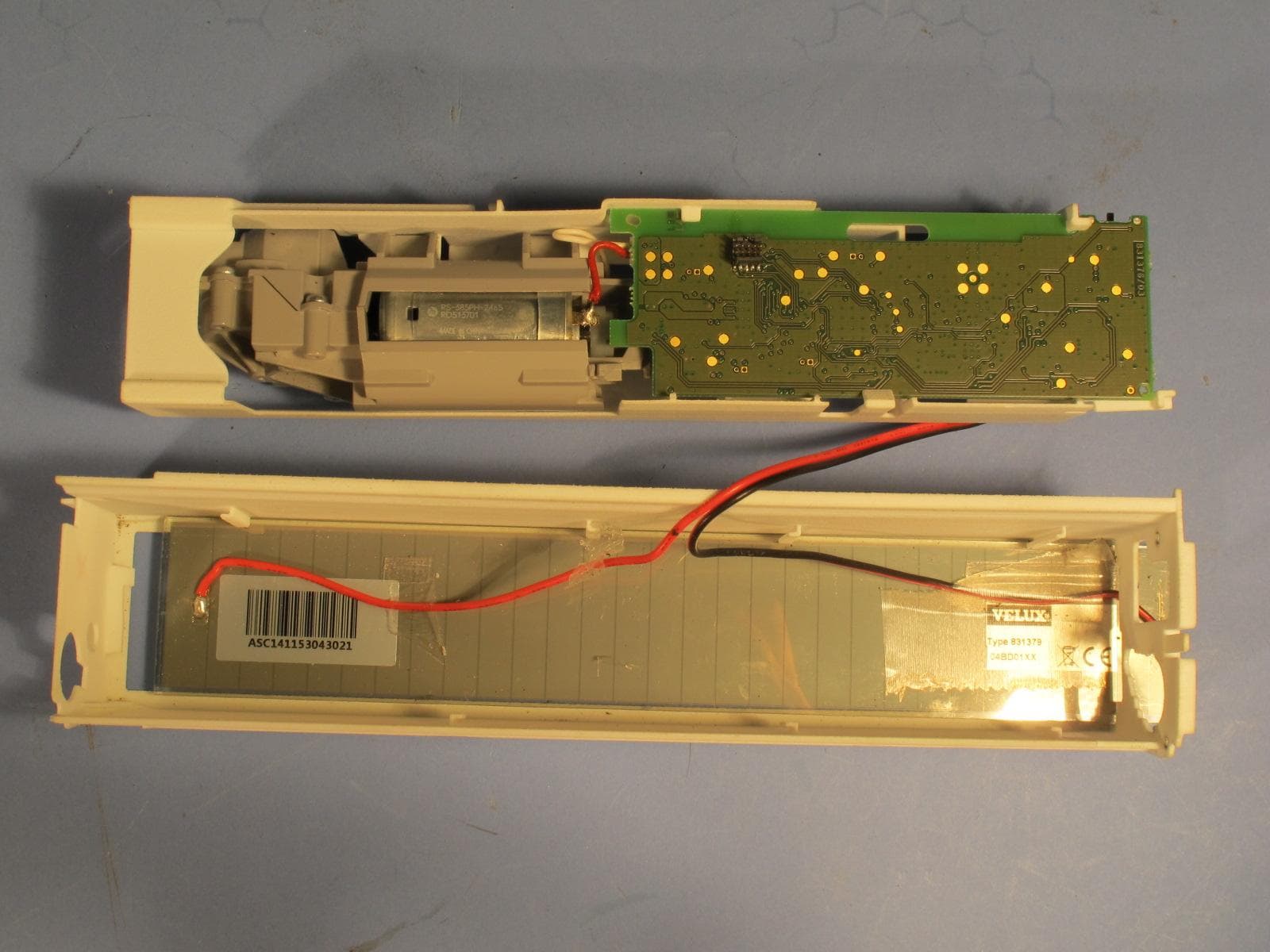
XSG865480
Mar 02, 2015Battery operated Blind
Equipment Class
DTS - Digital Transmission System
XSG832876
Feb 13, 2013Battery operated window opener
Equipment Class
DTS - Digital Transmission System
XSG863820
Jun 15, 2010Motor unit for solar/battery powered blinds
Equipment Class
DTS - Digital Transmission System