XTE-ULPAP110ACCESS POINT
Ingenu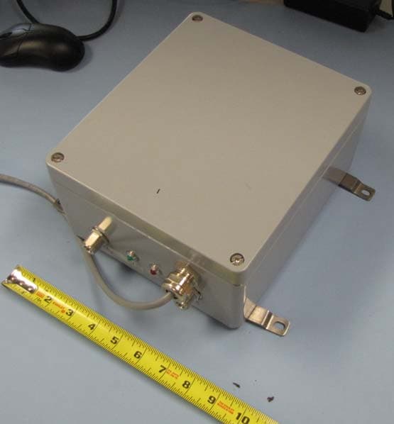
Click to zoom
Application Details
- Equipment Class
- DTS - Digital Transmission System
- Date of Grant
- Nov 08, 2010
- Application Purpose
- Original Equipment
- Date of Application
- Nov 07, 2010
- Equipment Note
- ACCESS POINT
- Frequency Range
- 2402.00000000 - 2475.63000000
- Company
- Ingenu
- Country
- United States
Documents & Files
Document Text
Text extracted from the exhibit documents filed with the FCC. Open a document above to read the original.
Users Manual
Access Point User’s Guide 012-0001-00 FCC Compliance and Advisory Statement This hardware device complies with Part 15 of the FCC Rules. Operation is subject to the following two conditions: 1) this device may not cause harmful interference, and 2) this device must accept any interference received, including interference that may cause undesired operation. This equipment has been tested and found to comply with the limits for a Class B digital device, pursuant to Part 15 of the FCC Rules. These limits are designed to provide reasonable protection against harmful interference in a residential installation. This equipment generates, uses, and can radiate radio frequency energy and, if not installed or used in accordance with the instructions, may cause harmful interference to radio communications. However, there is no guarantee that interference will not occur in a particular installation. If this equipment does cause harmful interference to radio or television reception, which can be determined by turning the equipment off and on, the user is encouraged to try to correct the interference by one or more of the following measures: 1) reorient or relocate the receiving antenna; 2) increase the separation between the equipment and the receiver; 3) connect the equipment to an outlet on a circuit different from that to which the receiver is connected; 4) consult the dealer or an experienced radio/TV technician for help. Any changes or modifications not expressly approved by the party responsible for compliance could void the user's authority to operate the equipment. Where shielded interface cables have been provided with the product or specified additional components or accessories elsewhere defined to be used with the installation of the product, they must be used in order to ensure compliance with FCC regulations. Canadian DOC Statement This digital device does not exceed the Class B limits for radio noise emissions from digital apparatus specified in the interference-causing equipment standard entitled "Digital Apparatus," ICES-003 of the Department of Industry. Ultra-Link Processing™ - Access Point Access Point User’s Guide 012-0001-00 P a g e | i On-Ramp Wireless © 2010 Table of Contents Product Overview ......................................................................................................................................... 3 Enclosure Features .................................................................................................................................... 3 Power-Over-Ethernet (PoE) ...................................................................................................................... 3 Lightning Protection .............................................................................................................................. 3 Environmental/Operational Parameters .................................................................................................. 4 Installation .................................................................................................................................................... 5 Professional Installation ............................................................................................................................ 5 Vertical Mounting ..................................................................................................................................... 5 Wall Mount ........................................................................................................................................... 5 Pole Mount ........................................................................................................................................... 6 Horizontal Mounting ................................................................................................................................. 6 Rack Mount ........................................................................................................................................... 6 Cabling........................................................................................................................................................... 8 Connections .............................................................................................................................................. 8 Antenna Parameters ................................................................................................................................. 9 Safety information ...................................................................................................................................... 11 Ultra-Link Processing™ - Access Point Access Point User’s Guide 012-0001-00 P a g e | ii On-Ramp Wireless © 2010 Ultra-Link Processing™ - Access Point Access Point User’s Guide 012-0001-00 P a g e | 3 On-Ramp Wireless © 2010 Product Overview Each Access Point supports tens of thousands of sensors and can simultaneously demodulate signals from up to 1000 sensors using a unique patented multiple access scheme. With 172 dB of total allowable path loss (FCC/IC regulatory regions) the ULP network can easily be deployed using a star topology configuration, overcoming the limitations of legacy wireless sensor networks (802.11, 802.15.4, 900 MHz FHSS) that require complicated mesh protocols to extend range or operate in a capacity limited simplex mode. Enclosure Features On-Ramp Wireless’ Ultra-Link Processing™ Access Point is housed in a rugged weatherproof enclosure that is ideal for both indoor and outdoor applications. Constructed of heavy gauge aluminum, it is designed for high temperature and corrosive environments. The AP can be mounted in a vertical or a horizontal orientation. The lid interior features a channeled gasket that provides environmental protection. The lid is secured to the housing with retained stainless steel heavy duty screws. For maintenance purposes, the lid can be opened (150 …
Text truncated - open the document above for the full version.
Users Manual
178 PCTEL, Inc. WEB: www.antenna.com GPS/AVIATION SPECIAL PURPOSE ANTENNAS GPS Timing Reference Antennas GPSL1-TMG-SPI-40N, 40 dB Internal Amplifi er with Integrated Lightning Protection The GPSL1-TMG-SPI-40N timing reference antennas are specifi cally designed for long-lasting, trouble-free deployments in congested cell-site applications. The low noise, high gain amplifi er is well suited to address attenuation issues associated with applications requiring longer cable runs. The proprietary quadrifi liar helix design, coupled with multistage fi ltering provides superior out-of-band rejection and lower elevation pattern performance than traditional patch antennas. Their unique radome shape sheds water and ice, while eliminating problems associated with bird perching. The antenna comes with surge compliant mounting that addresses industry grounding requirements. Custom models or site kits options are also available. This antenna is made of materials that fully comply with provisions stipulated by EU directives RoHS 2002/95/EC. The antenna provides integrated, on-board lightning protection capability that alleviates the need for downstream, in-line surge suppressors. The antenna also features ESD, reverse polarity protection and transit voltage suppression. Low Noise Amplifi er Specifi cations Frequency Band: 1575.42 +/-10 MHz Amplifi er Gain: 40 dB +/- 4 dB Nominal Impedance: 50 ohms Output VSWR: <2.0:1 Maximum Noise Figure: < 2.5 dB @ +25°C including pre-selector DC Voltage: 3.3-9.0 V (operating) ≤28.0 V (survivability) DC Current: < 30 mA @ 5 V Filtering: 3 stage fi ltering including pre-selector Out of Band Rejection: ≥ -60 dB @ +/- 50 MHz off center frequency Lightening Protection Compliance: Per EN61000-4-5 Level 4 1575.42 +/- 10 MHz 3.5 dBic50 ohms<1.5:1 Right hand circular N, female (one - bottom fed) Antenna Element Electrical Specifi cations Frequency Band Antenna Gain Nominal Impedance VSWRPolarizationConnector 7.25” H x 3.2” D (184 x 81 mm) 7.5” L x 4.4” W x 3.8” D (190 x 112 x 96 mm) 0.75 lbs (0.34 kg) White Mechanical Specifi cations Antenna Dimensions Shipping Dimensions Antenna Weight Radome Color -40°C to +85°C95% Environmental Specifi cations Temperature RangeHumidity GPSL1-TMG-SPI-40NDoes not include mounting hardware. GPSL1-TMG-SPI-40NCB Includes heavy duty mount (GPS-TMG-MHD), a grounding screw and lug nut GPSL1-TMG-SPI-40N GPSL1-TMG-SPI-40NCB Mounting All mounting options fi t pipes of 1”-1.45” (25 mm-37 mm) maximum diameter. ModelOptions
Users Manual
L-COM, INC. 45 BEECHWOOD DRIVE NORTH ANDOVER, MA 01845 WWW.L-COM.COM E-MAIL: [email protected] PHONE: 1-800-343-1455 FAX: 1-978-689-9484 © L-com, Inc. All Rights Reserved. L-com Global Connectivity and the L-com logo are registered marks. 2.4 GHz 9 dBi Omni-Directional with 7° Down-Tilt Antenna Applications and Features Applications: y 2.4 GHz ISM Band y ISP Base Stations y IEEE 802.11b/g Wireless LAN y Public Wireless Hotspot/WiFi Access Points y Multipoint and Mesh Applications Features: y Electrical Down Tilting Pattern for Excellent Coverage y Commercial Grade Radiating Elements y Integral N-Female connector y Durable UV-stable fiberglass radome y Includes heavy duty pole mounting brackets Model: HG2409UDT-PRO Features Professional Grade The HyperGain® HG2409UDT-PRO is a Profession Grade Omni-Directional Down-Tilt antenna that can be used for Commercial installations. The antenna features high gain and superior VSWR. The unit is optimized for the 2.4GHz ISM band. The pattern is electrically tilted downward to improve coverage from higher mounting elevations in difficult sites such as apartment complexes and similar installations. Superior Performance The HG2409UDT-PRO antenna is specifically designed from commercial applications. Electrical down tilting assures excellent coverage from higher mounting elevations to extend coverage over a larger area. It is ideally suited for close-in systems, typically found in apartment complex installations, neighborhood networks, industrial complexes, mobile home parks, marinas, truck stops and shopping centers. Because of the unique design of the HyperGain® HG2409UDT-PRO, nulls are eliminated in many cases, and the antenna can be used with many and varied wireless systems. The mounting hardware is industrial grade and protected from the elements. The fiberglass radome provides weatherproof protection of the antenna elements and electronics. The antenna base is stainless steel, providing strength and resistance to the environment. The radiating elements of the HG2408U-PRO utilize an air dielectric for lowest loss and superior radiating efficiency. The design is factory tuned for superior performance. Rugged and Weatherproof This antenna’s construction features a durable fiberglass radome for durability and aesthetics. Its mounting system features twin heavy-duty mounting brackets and U-Bolts for superior strength. The commercial grade elements provide long life in hostile environments. L-COM, INC. 45 BEECHWOOD DRIVE NORTH ANDOVER, MA 01845 WWW.L-COM.COM E-MAIL: [email protected] PHONE: 1-800-343-1455 FAX: 1-978-689-9484 © L-com, Inc. All Rights Reserved. L-com Global Connectivity and the L-com logo are registered marks. Specifications Electrical Specifications Frequency Range 2400-2500 MHz VSWR ≤1.5 Gain 9 dBi Rated power 150W Polarization Type Vertical Polarization Electrical Down Tilt 7 +/- 2° Beamwidth 11° Input Impedance 50Ω Lightning Protection Direct Ground Mechanical Specifications Connector Type N-Female Length 32 in. (0.80 m) Weight (w/ mounting bracket) 2.8 lbs. (1.27 kg) Radome Diameter 1.5 in. (38.1 mm) Base Diameter 1.7 in. (43.2 mm) Base Length 4.7 in. (119.4 mm) Radome Material Gray Fiberglass Rated Wind Survival >135/MPH Pole Mounting Hardware 1.25in.-2in. (32-50 mm) Antenna Gain Patterns
ID Label/Location Info
See exterior photo “label location”
Internal Photos
Cavity filter over main board. Main board Main Board backside. RF board with Shields Removed.
RF Exposure Info
Prediction of MPE limit at a given distance Equation from page 18 of OET Bulletin 65, Edition 97-01where: S = power density P = power input to the antennaG = power gain of the antenna in the direction of interest relative to isotropicR = distance to the center of radiation of the antenna Maximum peak output power at antenna input terminal: 29.81 (dBm) Maximum peak output power at antenna input terminal: 957 (mW) Antenna gain(typical): 9 (dBi) Maximum antenna gain: 7.94 (numeric) Prediction distance: 25 (cm) Sourse Based Time Average Duty Cycle: 100 (%) Prediction frequency: 2400 (MHz) MPE limit for uncontrolled exposure at prediction frequency: 1.0 (mW/cm^2) Power density at prediction frequency: 0.968 (mW/cm^2) Power density at prediction frequency: 9.68 (W/m^2) Margin of Compliance: 0.14 (dB) 2 4 R PG S π =
Test Report
Nemko USA, Inc. 11696 Sorrento Valley Rd., Suite F San Diego, CA 92121-1024 Phone (858) 755-5525 Fax (858) 452-1810 FCC Part 15 Subpart C, 15.247 : 05/11/2010 CERTIFICATION TEST REPORT Report Number: 2010 10157899 FCC Project Number: 61586-1 Nex Number: 157899 Applicant: O N-RAMP WIRELESS 10920 V IA FRONTERA SUITE 200 San Diego, CA 92127 Equipment Under Test (EUT): ON-RAMP WIRELESS ACCESS POINT Model: ULPAP110 FCC ID: XTE-ULPAP110 IC: 8655A-ULPAP100 In Accordance With: FCC Part 15 Subpart C, 15.247 IC RSS-210 Issue 7 June 2007 IC RSS-Gen Issue 2 June 2007 Tested By: Nemko USA Inc. 11696 Sorrento Valley Road, Suite F San Diego, CA 92121 Authorized By: Alan Laudani, EMC/RF Test Engineer Date: October 18, 2010 Total Number of Pages: 41 Nemko USA, Inc. 11696 Sorrento Valley Road, Suite F, San Diego, CA 92121 Phone (858) 755-5525 Fax (858) 452-1810 FCC ID: XTE-ULPAP100 Report Number: 2010 10157899 FCC IC: 8655A-ULPAP100 Specification: FCC Part 15 Subpart C, 15.247 Page 2 of 41 Section1: Summary of Test Results General All measurements are traceable to national standards These tests were conducted on a sample of the equipment for the purpose of demonstrating compliance with FCC Part 15; Subpart C and IC RSS-210. Radiated tests were conducted is accordance with ANSI C63.4-2003. Radiated emissions are made on an open area test site. A description of the test facility is on file with the FCC and IC. The assessment summary is as follows: Apparatus Assessed: On-Ramp Wireless Access Point Model: ULPAP110 Specification: FCC Part 15 Subpart C, 15.247 IC RSS-210 Issue 7 June 2007 Date Received in Laboratory: October 4, 2010 Compliance Status: Complies Exclusions: None Non-compliances: None Nemko USA, Inc. 11696 Sorrento Valley Road, Suite F, San Diego, CA 92121 Phone (858) 755-5525 Fax (858) 452-1810 FCC ID: XTE-ULPAP100 Report Number: 2010 10157899 FCC IC: 8655A-ULPAP100 Specification: FCC Part 15 Subpart C, 15.247 Page 3 of 41 1.1 Report Release History REVISION DATE COMMENTS - October 18, 2010 Prepared By: Alan Laudani - October 18, 2010 Initial Release: Alan Laudani Note that the results contained in this report relate only to the items tested and were obtained in the period between the date of initial receipt of samples and the date of issue of the report. This test report has been completed in accordance with the requirements of ISO/IEC 17025. Nemko USA Inc. authorizes the applicant to reproduce this report provided it is reproduced in its entirety and for use by the company’s employees only. Any use which a third party makes of this report, or any reliance on or decisions to be made based on it, are the responsibility of such third parties. Nemko USA Inc. accepts no responsibility for damages, if any, suffered by any third party as a result of decisions made or actions based on this report. TESTED BY: _ _ Date: October 18, 2010 Alan Laudani, EMC Test Engineer Nemko USA, Inc. 11696 Sorrento Valley Road, Suite F, San Diego, CA 92121 Phone (858) 755-5525 Fax (858) 452-1810 FCC ID: XTE-ULPAP100 Report Number: 2010 10157899 FCC IC: 8655A-ULPAP100 Specification: FCC Part 15 Subpart C, 15.247 Page 4 of 41 TABLE OF CONTENTS Section1: Summary of Test Results ............................................................................ 2 1.1 Report Release History ........................................................................................ 3 Section 2: Equipment Under Test ................................................................................ 5 2.1 Product Identification ............................................................................................ 5 2.2 Samples Submitted for Assessment ..................................................................... 5 2.3 Theory of Operation.............................................................................................. 6 2.4 Technical Specifications of the EUT ..................................................................... 6 Section 3: Test Conditions ........................................................................................... 7 3.1 Specifications ....................................................................................................... 7 3.2 Deviations From Laboratory Test Procedures...................................................... 7 3.3 Test Environment ................................................................................................. 7 3.4 Test Equipment .................................................................................................... 8 Section 4: Observations ............................................................................................... 9 4.1 Modifications Performed During Assessment....................................................... 9 4.2 Record Of Technical Judgements ........................................................................ 9 4.3 EUT Parameters Affecting Compliance ................................................................ 9 4.4 Test Deleted ......................................................................................................... 9 4.5 Additional Observations........................................................................................ 9 Section 5: Results Summary ...................................................................................... 10 5.1 Test Results........................................................................................................ 10 Appendix A: Test Results........................................................................................... 11 Section 15.207(a) – Power Line Conducted Emissions................................................. 11 Section 15.215(c) – 20 dB / 99% Bandwidth ................................................................. 16 Section 15.247(a)(2) – Minimum 6dB RF Bandwidth .................................................... 19 Section 15.247(b)(1) – Peak Output Power..............................…
Text truncated - open the document above for the full version.
Contact Information
Applicant
Eber Lambert(SR. DIRECTOR, ENGINEERING PROGRAM MANAGEMENT)
Test Firm
Nemko USA, Inc. - San Diego EMC DivisionJan Blomgren
[email protected]760-444-3500
Technical Specifications
| # | Rule Parts | Frequency Range | Power Output |
|---|---|---|---|
| 1 | 15C | 2.40 GHz - 2.48 GHz | 957.00 mW |
Other Applications from Ingenu
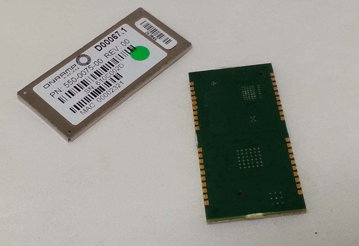
XTE-NODE102
Sep 21, 2015Wireless network module
Equipment Class
DSS - Part 15 Spread Spectrum Transmitter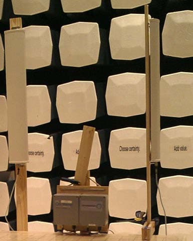
XTE-ULPAP210
May 12, 2015Sectorized RPMA Access Point
Equipment Class
DTS - Digital Transmission System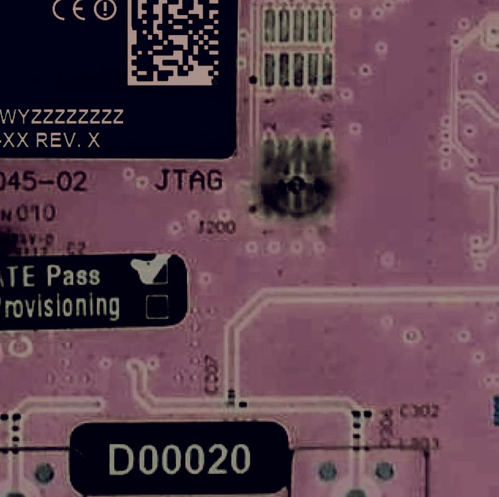
XTE-TRN-2012
Jun 02, 2013Meter Communication Module
Equipment Class
DTS - Digital Transmission System
XTE-TRN-2113
Jun 02, 2013Meter Communications Module
Equipment Class
DTS - Digital Transmission System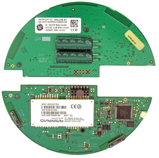
XTE-EM110100
Sep 30, 2012Electric Meter Communications Module
Equipment Class
DSS - Part 15 Spread Spectrum Transmitter