XTE-ULPENODE110On-Ramp Wireless eNode
Ingenu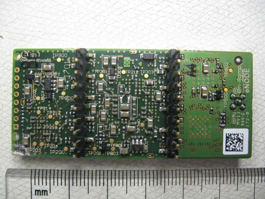
Click to zoom
Application Details
- Equipment Class
- DTS - Digital Transmission System
- Date of Grant
- Nov 04, 2010
- Application Purpose
- Original Equipment
- Date of Application
- Nov 04, 2010
- Equipment Note
- On-Ramp Wireless eNode
- Frequency Range
- 2402.00000000 - 2476.00000000
- Company
- Ingenu
- Country
- United States
Documents & Files
Document Text
Text extracted from the exhibit documents filed with the FCC. Open a document above to read the original.
Users Manual
eNode User Manual 010-0002-00 The information disclosed in this document is proprietary to On-Ramp Wireless, and is not to be used or disclosed to unauthorized persons without the written consent of On-Ramp Wireless. The recipient of this document shall respect the security of this document and maintain the confidentiality of the information it contains. The master copy of this document is stored in electronic format, therefore any hard or soft copy used for distribution purposes must be considered as uncontrolled. Reference should be made to On-Ramp Wireless to obtain the latest version. Ultra-Link Processing™ - eNode eNode/User Manual 010-0002-00 P a g e | ii On-Ramp Wireless © 2010 Document Control History Version Date Author Remarks 1.0 2/12/10 ORW Initial Release 1.1 2/29/10 ORW Updated with certification comments (Sect 4.3 and 4.4) 2.0 7/28/10 ORW Updated for ULPENODE110 2.1 09/03/10 ORW Updated max pwr consumption, input voltage range. Removed UART statement. Updated formatting 3 09/16/10 ORW Applied new formatting, modified footer to include copyright statement. 4 11/04/10 ORW Updated section 4.3 Usage, to include Integrators and RF Exposure statements Ultra-Link Processing™ - eNode eNode/User Manual 010-0002-00 P a g e | 1 On-Ramp Wireless © 2010 Table of Contents 2 Scope ............................................................................................................................................................................... 3 2.1 What does this document cover? ........................................................................................................................... 3 2.2 Who should use this Manual? ................................................................................................................................. 3 2.3 Reference documents ............................................................................................................................................. 3 3 Introduction .................................................................................................................................................................... 4 4 Approvals ........................................................................................................................................................................ 5 4.1 FCC .......................................................................................................................................................................... 5 4.2 Industry Canada ...................................................................................................................................................... 5 4.3 Usage ....................................................................................................................................................................... 5 4.3.1 Integrators ....................................................................................................................................................... 6 4.3.2 RF Exposure Statement ................................................................................................................................... 6 4.4 Antennas ................................................................................................................................................................. 6 5 eNode Overview and Interfaces ..................................................................................................................................... 7 5.1 Hardware Interface ................................................................................................................................................. 7 5.1.1 SPI Slave Interface ........................................................................................................................................... 7 5.1.2 Pin Description ................................................................................................................................................ 7 5.1.3 Electrical Characteristics ................................................................................................................................. 8 5.1.4 eNode dimensions .......................................................................................................................................... 8 5.2 Software Interface ................................................................................................................................................ 10 5.3 Host Interface........................................................................................................................................................ 10 5.3.1 Functional Description .................................................................................................................................. 10 5.3.2 Host Interface Protocol ................................................................................................................................. 11 5.3.3 Signal Description .......................................................................................................................................... 11 5.3.4 Master Request / Slave Ready ...................................................................................................................... 11 5.3.5 Slave Request ................................................................................................................................................ 11 5.3.6 Other Signals ................................................................................................................................................. 11 5.3.7 SPI Interface Driver ....................................................................................................................................... 12 5.4 Software Upgrade Protocol.....................................................................................…
Text truncated - open the document above for the full version.
Cover Letter(s)
1 Mark Briggs To: Deniz Demirci Subject: RE: TCB certification - On-Ramp Wireless Inc. Model ULPN110 (CG1386) Deniz Thank you for your response to our questions. This will be uploaded with the application documents. Regards, Mark Mark Briggs Reviewing Engineer Elliott Labs - An NTS Company 41039 Boyce Road Fremont, CA 94538 [email protected] From: Deniz Demirci Sent: Thursday, November 04, 2010 5:19 PM To: Mark Briggs Subject: RE: TCB certification - On-Ramp Wireless Inc. Model ULPN110 (CG1386) Hi Mark, The responses are in red fonts; 1) External Photos – these appear to be for the developer board and not the module and could cause confusion as to what the device being certified is (module or developer board). We only need a photo showing the top and bottom of the module. You could use the rear view of the module (page 2, upper picture from internal photos) for the external rear view and a photograph of the front view (first photograph of internal photos). External photos are updated. Please see “External Photographs v2.pdf” 2) Attestation Letters – from the block diagram and associated operational description it appears the device can be configured to operate from 2402 – 2480 MHz but the frequency range covered by the application is 2402 – 2476MHz. We will need a description/attestation explaining how operation for devices sold into Canada and USA is restricted to the frequencies covered by the application. The commissioning procedure is described in “eNode_Theory_of_Operation_010-0003-00_v2.1.pdf” 6.1.2 Interface section .This section was amended during previous application as an audit response) The customer has amended the user manual also as; The air interface supports operation on channels in the 2402 MHz – 2476 MHz range for FCC/IC regulatory domains and 2402‐2481 for the ETSI regulatory domain. Before the ULP Node becomes operational it must undergo a commissioning procedure, during which critical information required for operation is entered into the device and stored in non‐volatile storage. It is during the initial commissioning procedure that the regulatory domain under which the device will operate is set. Subsequent configuration of the device during operation is checked against the commissioned regulatory domain and non‐permitted channels or transmit power levels are rejected and the device will not transmit until a permissible configuration per the commissioned regulatory domain is set. 3) The Company Number on the RSS 102 Annex A form is incorrect. As this device is exempt from RSS-120 and you have submitted Annex C form and technical brief justifying the exemption I do not think Annex A is required. If you wish to submit an Annex A please correct the company number on the form. Please don’t use the Annex A for the filing 2 4) The User Manual does not contain information to module integrator regarding the labeling of the host system or rf exposure statements that must be provided to the end user. The user manual has been updated by the customer as; 4.3 Usage FCC ID: XTE‐ULPENODE110. IC: 8655A‐ULPENODE110. This device is only authorized for use in portable applications. To meet FCC and other national RF exposure requirements the antenna for this device must be installed to ensure a separation distance of at least 20cm (8 inches) from the antenna to a person. 4.3.1 Integrators A label showing the FCC ID and IC designators, listed above, must be affixed to the exterior of any device containing the eNode (if the eNode is not visible). The exterior label must include: Contains FCC ID: XTE‐ ULPENODE110, IC 8655A‐ULPENODE110. 5) Test report – Power measurement (pages 21 – 23): Can you please clarify the method used – was this sample detector and power averaging over 100 traces or peak detector max hold? From the plots the number of averages appears to be 1 which is why I ask The method was used; sample detector and power averaging over 100 traces The Rohde & Schwarz FSEK spectrum analyzer shows the average counts on the screen but not on the plots. The green “1SA” at right side of the plot means; Trace 1, sample detector The green “1AV” at left side of the plot means: Trace 1, trace average 6) Test report – power density measurement: Pretty much the same question as from above; was this with averaging enabled or not? The test method is the same as power measurement test method 7) Test report – transmitter and receiver radiated spurious: Can you please confirm the frequency range that was evaluated, was it from 30 MHz or was it just limited to above 1GHz? EUT was tested form 30 MHz to 26 GHz with all configurations. There were no measurable emissions observed related to the transmitter in the 30 MHz – 1000 MHz range. Best regards, Deniz Deniz Demirci Senior Wireless/EMC Technologist National Technical Systems (NTS Canada) Phone: 403-568-6605 ext 244 fax: 403-568-6970 cell: 403-618-1807 email:[email protected] web: http://www.ntscorp.com/about/locations
Cover Letter(s)
Friday October 15, 2010 Attn: Reviewing agency or TCB Re: On-Ramp Wireless eNode FCC and IC modular approval FCC ID: XTE-ULPENODE110 IC: 8655A- ULPENODE110 Client; On-Ramp Wireless Inc. 10902 Via Frontera, Suite 200 San Diego, CA 92127 USA Tel: (858) 592-6008 The scope of this application is to certify On-Ramp Wireless eNode model ULPN110 against FCC (Part 15 Subpart C section 15.247) and Industry Canada (RSS 210, Issue 7) The modular unit is a 2402 MHz to 2476 MHz transceiver with Spread Spectrum DBPSK modulation The client is asking for FCC and Industry Canada modular approval RSS-102 Issue 4 RF Exposure evaluation; 2.5.1 Exemption from Routine Evaluation Limits – SAR Evaluation The chapter 4.3 (Page 8) of eNode User Manual defines the distance as; This device must be installed to ensure a separation distance of at least 20 cm (8 inches) from the antenna to a person. 2.5.2 Exemption from Routine Evaluation Limits – RF Exposure Evaluation The peak power output of the device is 20.10 dBm at 2402 MHz The maximum antenna gain is 5 dBi The calculated maximum radiated e.i.r.p. is 25.10 dBm (0.32 W) which is less than 5 W Therefore the unit is exempt from RSS-102 Issue 4, routine evaluation limits Best regards, Glen Moore Wireless/EMC Manager National Technical Systems (NTS Canada) P:403-568-6605, ext 223 C:403-809-4967 F:403-568-6970 Email: [email protected] Website: http://www.ntscorp.com/about/locations/calgary/
External Photos
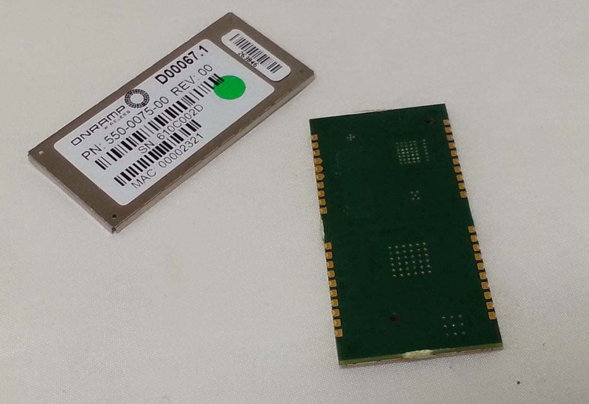
C-0095298-RA-1-1 On Ramp FCC/IC Exhibit Model ULPN110 FCC ID: XTE-ULPENODE110 IC: 8655A-ULPENODE110 Date: October 28, 2010 Revision #: 2 External Photographs Module front view with host unit Module rear view
ID Label/Location Info
57.075 59.660 54.607 12.127 13.848 3.637 n1.500 (x2) 1.764 1.169 (x2) 1.147 (x2) 19.913 5 38.042 16.615 2.703 (x2) 5.994 5.994 12.286 (x2) 3 J703 Pin 10 6 3 J701 Pin 1 9.652 3.810 2.522 5.486 2.964 1.593 25.400 26.450 4 DWG NO.FSCM NO. DATE APPROVED DRAWN REV REVISIONS MFG CHECKED ZONE SCALE REV B DATE APPROVED 2010-07-29 SCT DESCRIPTION QA SHEET SIZE 2:1 Connector J701 Pinout Pin 1 - RXD0 Pin 2 - TXD0 Pin 3 - T_OUT Pin 4 - RESET Pin 5 - SPI-CSO Pin 6 - SPI-SCLK Pin 7 - SPI-MOSI Pin 8 - SPI-MISO Pin 9 - GND Pin 10 - GND Connector J703 Pinout Pin 1 - VBATT Pin 2 - VBATT Pin 3 - RXD1 Pin 4 - TXD1 Pin 5 - GND Pin 6 - SPI-MRQ Pin 7 - SPI-SRQ Pin 8 - SPI-SRDY Pin 9 - GND Pin 10 - GND 1 of 1 CONFIDENTIAL AND/OR PROPRIETARY INFORMATION This document contains proprietary information and shall not be disclosed in whole or in part without express written permission of OnRamp Wireless Inc. Notes 1. All dimensions in MILLIMETERS [INCHES] unless stated otherwise. 2. Tolerances are 0.X [0.X] +/- 0.5 [0.020"], 0.XX [.XXX] 0.25 [+/- 0.010"] 3. Connectors J701 and J703 are 0.100 SIP Headers, Greenconn P/N GPHC101-10-02-A49X or equivalent. 4. Connector J600 is an MMCX Series, Johnson P/N 135-3701-201 or equivalent. 5. Place product label where shown. 6. Area for manufacturing bar code label. Printed Circuit Assembly, Outline, Mechanical, eNode R8 1 508-0001-00
Internal Photos
C-0095298-RA-1-1 On Ramp FCC/IC Exhibit Model ULPN110 FCC ID: XTE-ULPENODE110 IC: 8655A-ULPENODE110 Date: July 21, 2010 Revision #: 1 Internal Photographs Module front view with host unit (cover on) Module cover off C-0095298-RA-1-1 On Ramp FCC/IC Exhibit Model ULPN110 FCC ID: XTE-ULPENODE110 IC: 8655A-ULPENODE110 Date: July 21, 2010 Revision #: 1 Module rear view Radio part
RF Exposure Info
Confidentiality Statement: This report and the information contained herein represent the results of testing articles/products identified and selected by the client. The tests were performed to specifications and/or procedures approved by the client. National Technical Systems (“NTS”) makes no representations expressed or implied that such testing fully demonstrates efficiency, performance, reliability, or any other characteristic of the articles being tested, or similar products. This report should not be relied upon as an endorsement or certification by NTS of the equipment tested, nor does it represent any statement whatsoever as to its merchantability or fitness of the test article or similar products for a particular purpose. This document shall not be reproduced except in full without written approval from National Technical Systems (“NTS”) and the customer. MPE Report For On-Ramp Wireless eNode FCC ID: XTE-ULPENODE110 IC: 8655A- ULPENODE110 Project Code C-0095298 (Report C-0095298-RA-3-1) Revision: 1 (This report supersedes CG-1386-RA-3-1) October 15, 2010 Prepared for: On-Ramp Wireless Inc Author: Deniz Demirci Senior Wireless / EMC Technologist Approved by: Nick Kobrosly Director of Canadian operations C-0095298-RA-3-1 On Ramp MPE Calculation Model ULPN110 FCC ID: XTE-ULPENODE110 IC: 8655A-ULPENODE110 ______________________________________________________________________ The test results contained in this report refer exclusively to the product(s) presented for testing. The test results do not cover models or products not referred herein. This test report should not be published or duplicated in whole or part without permission from the testing body and the customer. NTS Product Integrity Laboratory, 5151-47 th Street N.E. Tel: 403-568-6605, Fax: 403-568-6970 Confidential Page 2 of 6 October 15, 2010 Test Facility: National Technical Systems, Canada Product Integrity Laboratory 5151-47 th Street, N.E. Calgary Alberta T3J 3R2 Accreditation Numbers: 0214.22 Electrical 0214.23 Mechanical Accredited by A2LA The American Association for Laboratory Accreditation CLIENTS SERVED: All interested parties FIELDS OF TESTING: Electrical/Electronic, Mechanical/Physical ACCREDITATION DATE:: May 14, 2009 VALID TO: February 28, 2010 Applicant: On-Ramp Wireless Inc. 10902 Via Frontera, Suite 200 San Diego, CA 92127 USA Tel: (858) 592-6008 Customer Representative: Rob Boesel / Jason Wilson Tel: (852) 312-8361 [email protected] / [email protected] C-0095298-RA-3-1 On Ramp MPE Calculation Model ULPN110 FCC ID: XTE-ULPENODE110 IC: 8655A-ULPENODE110 ______________________________________________________________________ The test results contained in this report refer exclusively to the product(s) presented for testing. The test results do not cover models or products not referred herein. This test report should not be published or duplicated in whole or part without permission from the testing body and the customer. NTS Product Integrity Laboratory, 5151-47 th Street N.E. Tel: 403-568-6605, Fax: 403-568-6970 Confidential Page 3 of 6 October 15, 2010 Register of revisions Revision Date Description of Revisions 1 October 15, 2010 Initial release C-0095298-RA-3-1 On Ramp MPE Calculation Model ULPN110 FCC ID: XTE-ULPENODE110 IC: 8655A-ULPENODE110 ______________________________________________________________________ The test results contained in this report refer exclusively to the product(s) presented for testing. The test results do not cover models or products not referred herein. This test report should not be published or duplicated in whole or part without permission from the testing body and the customer. NTS Product Integrity Laboratory, 5151-47 th Street N.E. Tel: 403-568-6605, Fax: 403-568-6970 Confidential Page 4 of 6 October 15, 2010 1.0 INTRODUCTION 1.1 PURPOSE This Maximum Permissive Exposure report demonstrates compliance with FCC CFR 47 1.1310, 2.1091 and RSS-102 Issue 4, RF Exposure evaluation for Model ULPN110 which is categorized as “mobile”. The mobile classification applies when 20 cm or greater separation distance is maintained between the end user and all transmission antennas. The user documentation available to consumers indicates that the Module and antenna must not be used closer than 20 cm to head or body. 1.2 ANTENNA SPECIFICATIONS The Model ULPN110 has the following antenna gain specifications: • 5dBi Antenna NEARSON Part # S151FL-L-RMM-2450S • 2dBi Antenna NEARSON Part # S181FL-L-RMM- 2450S • 1dBi Antenna Hyperlink Technologies Part # HG2401RD-MMCX 2.0 RF EXPOSURE LIMITS AND EQUATIONS In compliance with FCC CFR 47 1.1310, the criteria listed in the table below shall be used to evaluate the environmental impact of human exposure to radio-frequency (RF) radiation as specified in 1.1303 (b). Limits for Maximum Permissible Exposure (MPE) Frequency Range (MHz) Electric Field Strength (V/m) Magnetic Field Strength (A/m) Power Density (mw/cm2) Average Time (minutes) (A) Limits for Occupational/Control Exposures (f=frequency) 30-300 61.4 0.2 1.0 6.0 300-1500 - - f/300 6.0 1500-100,000 - - 5.0 6.0 (B) Limits for General Population/Uncontrolled Exposure (f=frequency) 30-300 27.5 0.1 0.2 30.0 300-1500 - - f/1500 30.0 1500-100,000 - - 1.0 30.0 Friis Transmission Formula: Pd = (Pout * G) / (4πR²) Where, Pd = power density (mW/cm²) Pout = output power to antenna (mW) G = gain of antenna in linear scale R = distance between observation point and center of the radiator (cm) The resulted power density at a distance of 20cm can be calculated as follows: Power Density = (EIRP * Duty cycle) / (4πR²) C-0095298-RA-3-1 On Ramp MPE Calculation Model ULPN110 FCC ID: XTE-ULPENODE110 IC: 8655A-ULPENODE110 ______________________________________________________________________ The test results contained in this report refer exclusively to the product(s) presented for testing. The test results do not cover models or products not referred herein. This test report should not be published …
Text truncated - open the document above for the full version.
Test Report
Confidentiality Statement: This report and the information contained herein represent the results of testing articles/products identified and selected by the client. The tests were performed to specifications and/or procedures approved by the client. National Technical Systems (“NTS”) makes no representations expressed or implied that such testing fully demonstrates efficiency, performance, reliability, or any other characteristic of the articles being tested, or similar products. This report should not be relied upon as an endorsement or certification by NTS of the equipment tested, nor does it represent any statement whatsoever as to its merchantability or fitness of the test article or similar products for a particular purpose. This document shall not be reproduced except in full without written approval from National Technical Systems (“NTS”) and the customer. Certification Test Report CFR 47 FCC Part 15, Subpart C Section 15.247 Industry Canada RSS 210, Issue 7 On-Ramp Wireless eNode FCC ID: XTE-ULPENODE110 IC: 8655A-ULPENODE110 Project Code C-0095298 (Report C-0095298-RA-1-1) Revision: 1 (This report supersedes CG-1386-RA-1-2) July 21, 2010 Prepared for: On-Ramp Wireless Inc. Author: Deniz Demirci Senior Wireless / EMC Technologist Approved by: Nick Kobrosly Director of Canadian Operations C-0095298-RA-1-1 On Ramp Wireless Certification Test Report Model ULPN110 FCC ID: XTE-ULPENODE110 IC: 8655A-ULPENODE110 ______________________________________________________________________ The test results contained in this report refer exclusively to the product(s) presented for testing. The test results do not cover models or products not referred herein. This test report should not be published or duplicated in whole or part without permission from the testing body and the customer. NTS Product Integrity Laboratory, 5151-47 th Street N.E. Tel: 403-568-6605, Fax: 403-568-6970 Confidential Page 2 of 41 July 21, 2010 Report Summary Test Facility: National Technical Systems, Canada Product Integrity Laboratory 5151-47 th Street, N.E. Calgary Alberta T3J 3R2 Accreditation Numbers: 0214.22 Electrical 0214.23 Mechanical Accredited by A2LA The American Association for Laboratory Accreditation CLIENTS SERVED: All interested parties FIELDS OF TESTING: Electrical/Electronic, Mechanical/Physical ACCREDITATION DATE:: May 14, 2009 VALID TO: December 31, 2011 Applicant: On-Ramp Wireless Inc. 10902 Via Frontera, Suite 200 San Diego, CA 92127 USA Tel: (858) 592-6008 Customer Representative: Rob Boesel / Jason Wilson Tel: (852) 312-8361 [email protected] / [email protected] C-0095298-RA-1-1 On Ramp Wireless Certification Test Report Model ULPN110 FCC ID: XTE-ULPENODE110 IC: 8655A-ULPENODE110 ______________________________________________________________________ The test results contained in this report refer exclusively to the product(s) presented for testing. The test results do not cover models or products not referred herein. This test report should not be published or duplicated in whole or part without permission from the testing body and the customer. NTS Product Integrity Laboratory, 5151-47 th Street N.E. Tel: 403-568-6605, Fax: 403-568-6970 Confidential Page 3 of 41 July 21, 2010 Test Summary Deviations* from: Appendix Test/Requirement Description Base Standard Test Basis NTS Procedure Pass / Fail Applicable FCC Rule Parts Applicable Industry Canada Rule Parts A Power Line Conducted Emission No No No Pass FCC Subpart C 15.207 (a) RSS-Gen Issue 2 7.2.2 B 6 dB Bandwidth No No No Pass FCC Subpart C 15.247 (a) (2) RSS 210 Issue 7 A8.2 (a) C Occupied Bandwidth (99% emission bandwidth) No No No N/A N/A RSS-Gen Issue 2 4.6.1 D Peak Power Output No No No Pass FCC Subpart C 15.247 (b) (3) RSS 210 Issue 7 A8.4 (4) E Power Spectral Density No No No Pass FCC Subpart C 15.247 (e) RSS 210 Issue 7 A8.2 (b) F Conducted Spurious Emissions (TX) No No No Pass FCC Subpart C 15.247 (d) RSS 210 Issue 7 A8.5 G Conducted Spurious Emissions Band Edge No No No Pass FCC Subpart C 15.247 (d) RSS 210 Issue 7 A8.5 H Duty Cycle No No No N/A FCC Subpart C 15.35 (c) RSS-Gen Issue 2 4.5 I Radiated Spurious Emissions Band Edge No No No Pass FCC Subpart C 15.247, 15.205 RSS 210 Issue 7 2.6, A8.5 J Radiated Spurious Emissions (TX and RX) No No No Pass FCC Subpart C 15.247, 15.205 RSS 210 Issue 7 2.6, A8.5 RSS Gen Issue 2 4.10 Test Result: The product presented for testing complied with test requirements as shown above. Prepared By: _______________________ Deniz Demirci Senior Wireless / EMC Technologist Reviewed By: ______________________ Glen Moore Wireless / EMC Manager Approved By: ______________________ Alex Mathews Quality Management Representative C-0095298-RA-1-1 On Ramp Wireless Certification Test Report Model ULPN110 FCC ID: XTE-ULPENODE110 IC: 8655A-ULPENODE110 ______________________________________________________________________ The test results contained in this report refer exclusively to the product(s) presented for testing. The test results do not cover models or products not referred herein. This test report should not be published or duplicated in whole or part without permission from the testing body and the customer. NTS Product Integrity Laboratory, 5151-47 th Street N.E. Tel: 403-568-6605, Fax: 403-568-6970 Confidential Page 4 of 41 July 21, 2010 Table of Contents REPORT SUMMARY ........................................................................................................................................................2 TEST SUMMARY..............................................................................................................................................................3 REGISTER OF REVISIONS .............................................................................................................................................5 1.0 INTRODUCTION .........................................................................................................................…
Text truncated - open the document above for the full version.
Test Setup Photos
C-0095298-RA-1-1 On Ramp FCC/IC Exhibit FCC ID: XTE-ULPENODE110 IC: 8655A-ULPENODE110 Date: July 21, 2010 Revision #: 0 Test Setup Photographs Power Line AC Conducted Emission Radiated Emission setup with 5dBi Antenna Horizontal C-0095298-RA-1-1 On Ramp FCC/IC Exhibit FCC ID: XTE-ULPENODE110 IC: 8655A-ULPENODE110 Date: July 21, 2010 Revision #: 0 Radiated Emission setup with 5dBi Antenna Vertical, EUT vertical Radiated Emission setup with 5dBi Antenna vertical, EUT side C-0095298-RA-1-1 On Ramp FCC/IC Exhibit FCC ID: XTE-ULPENODE110 IC: 8655A-ULPENODE110 Date: July 21, 2010 Revision #: 0 Radiated Emission setup with 2 dBi Antenna horizontal Radiated Emission setup with 2 dBi Antenna vertical, EUT vertical C-0095298-RA-1-1 On Ramp FCC/IC Exhibit FCC ID: XTE-ULPENODE110 IC: 8655A-ULPENODE110 Date: July 21, 2010 Revision #: 0 Radiated Emission setup with 1 dBi Antenna horizontal Radiated Emission setup with 1dBi Antenna Vertical, EUT Vertical C-0095298-RA-1-1 On Ramp FCC/IC Exhibit FCC ID: XTE-ULPENODE110 IC: 8655A-ULPENODE110 Date: July 21, 2010 Revision #: 0 Radiated Emission setup with 1dBi Antenna vertical, EUT side
Contact Information
Applicant
Eber Lambert(SR. DIRECTOR, ENGINEERING PROGRAM MANAGEMENT)
Technical Contact
Test Firm
National Technical Systems, Inc.Nick Kobrosly
Technical Specifications
| # | Rule Parts | Frequency Range | Power Output |
|---|---|---|---|
| 1 | 15C | 2.40 GHz - 2.48 GHz | 102.00 mW |
Other Applications from Ingenu
XTE-NODE102
Sep 21, 2015Wireless network module
Equipment Class
DSS - Part 15 Spread Spectrum Transmitter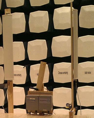
XTE-ULPAP210
May 12, 2015Sectorized RPMA Access Point
Equipment Class
DTS - Digital Transmission System
XTE-TRN-2012
Jun 02, 2013Meter Communication Module
Equipment Class
DTS - Digital Transmission System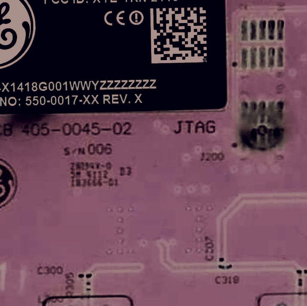
XTE-TRN-2113
Jun 02, 2013Meter Communications Module
Equipment Class
DTS - Digital Transmission System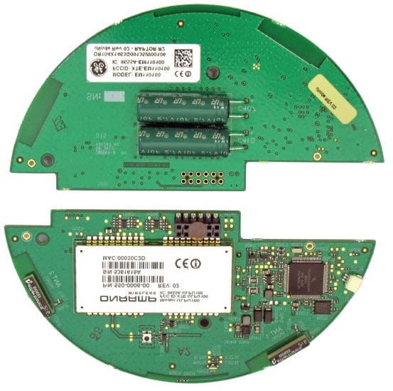
XTE-EM110100
Sep 30, 2012Electric Meter Communications Module
Equipment Class
DSS - Part 15 Spread Spectrum Transmitter