XTE-ULPENODE120On-Ramp Wireless eNode
Ingenu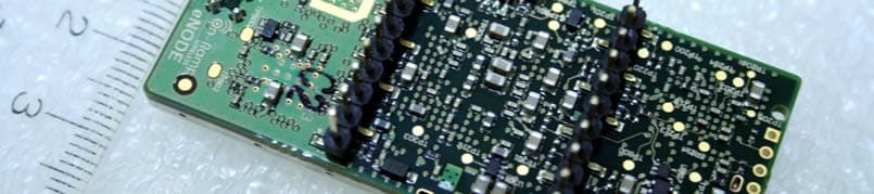
Click to zoom
Application Details
- Equipment Class
- DTS - Digital Transmission System
- Date of Grant
- Nov 24, 2011
- Application Purpose
- Original Equipment
- Date of Application
- Nov 24, 2011
- Equipment Note
- On-Ramp Wireless eNode
- Frequency Range
- 2400.00000000 - 2475.63000000
- Company
- Ingenu
- Country
- United States
Documents & Files
Document Text
Text extracted from the exhibit documents filed with the FCC. Open a document above to read the original.
Users Manual
On-Ramp Wireless Confidential and Proprietary. Restricted Distribution. This document is not to be used, disclosed, or distributed to anyone without express written consent from On-Ramp Wireless. The recipient of this document shall respect the security of this document and maintain the confidentiality of the information it contains. The master copy of this document is stored in electronic format, therefore any hard or soft copy used for distribution purposes must be considered as uncontrolled. Reference should be made to On-Ramp Wireless to obtain the latest revision. eNode User Manual On-Ramp Wireless Incorporated 10920 Via Frontera, Suite 200 San Diego, CA 92127 U.S.A. Copyright © 2011 On-Ramp Wireless Incorporated. All Rights Reserved. The information disclosed in this document is proprietary to On-Ramp Wireless Inc., and is not to be used or disclosed to unauthorized persons without the written consent of On-Ramp Wireless. The recipient of this document shall respect the security of this document and maintain the confidentiality of the information it contains. The master copy of this document is stored in electronic format, therefore any hard or soft copy used for distribution purposes must be considered as uncontrolled. Reference should be made to On-Ramp Wireless to obtain the latest version. By accepting this material the recipient agrees that this material and the information contained therein is to be held in confidence and in trust and will not be used, copied, reproduced in whole or in part, nor its contents revealed in any manner to others without the express written permission of On-Ramp Wireless Incorporated. On-Ramp Wireless Incorporated reserves the right to make changes to the product(s) or information contained herein without notice. No liability is assumed for any damages arising directly or indirectly by their use or application. The information provided in this document is provided on an “as is” basis. This document contains On-Ramp Wireless proprietary information and must be shredded when discarded. This documentation and the software described in it are copyrighted with all rights reserved. This documentation and the software may not be copied, except as otherwise provided in your software license or as expressly permitted in writing by On-Ramp Wireless, Incorporated. Any sample code herein is provided for your convenience and has not been tested or designed to work on any particular system configuration. It is provided “AS IS” and your use of this sample code, whether as provided or with any modification, is at your own risk. On-Ramp Wireless undertakes no liability or responsibility with respect to the sample code, and disclaims all warranties, express and implied, including without limitation warranties on merchantability, fitness for a specified purpose, and infringement. On-Ramp Wireless reserves all rights in the sample code, and permits use of this sample code only for educational and reference purposes. This technology and technical data may be subject to U.S. and international export, re-export or transfer (“export”) laws. Diversion contrary to U.S. and international law is strictly prohibited. Ultra-Link Processing™ is a trademark of On-Ramp Wireless. Other product and brand names may be trademarks or registered trademarks of their respective owners. eNode User Manual 010-0002-00 Rev. 08 November 8, 2011 On-Ramp Wireless Confidential and Proprietary iii 010-0002-00 Rev. 08 Contents 1 Introduction ........................................................................................................... 1 2 Ultra-Link Processing Overview .......................................................................... 2 3 Regulatory Approvals ........................................................................................... 3 3.1 Federal Communications Commission ...................................................................................... 3 3.2 Industry Canada ......................................................................................................................... 3 3.3 Usage ......................................................................................................................................... 4 3.3.1 Integrators ........................................................................................................................ 4 3.3.2 RF Exposure Statement ................................................................................................... 4 3.4 Antennas .................................................................................................................................... 4 4 eNode Interfaces ................................................................................................... 6 4.1 Hardware Interface..................................................................................................................... 6 4.1.1 SPI Slave Interface ........................................................................................................... 6 4.1.2 Pin Description ................................................................................................................. 6 4.1.3 Electrical Characteristics .................................................................................................. 7 4.1.4 eNode Dimensions ........................................................................................................... 7 4.2 Software Interface ...................................................................................................................... 9 4.3 Host Interface ............................................................................................................................. 9 4.3.1 Functional Description ...................................................................................................... 9 4.3.2 Host Interface Protocol .....................................................................…
Text truncated - open the document above for the full version.
Cover Letter(s)
On-Ramp Wireless, Inc 10920 Via Frontera, Suite 200 San Diego, CA 92127, USA +1 858 592 6008 : phone +1 858 592 6009 : fax [email protected] www.onrampwireless.com On-Ramp Wireless, Inc. 1 November 7, 2011 Federal Communications Commission Equipment Authorization Branch 7435 Oakland Mills Road Columbia, MD 21046 Request for modular approval On-Ramp Wireless, Inc. FCC ID: XTE-ULPENODE120 FCC Part 15 Certification Dear Application Examiner, On-Ramp Wireless, Inc. module FCC ID: XTE-ULPENODE120 is seeking FCC authorization as a modular transmitter. The requirements of the FCC Part 15.212 are met f o r a l l requirements listed below. 1. The modular transmitter must have its own RF shielding The radio portion of this module has its own RF shielding. 2. The modular transmitter must have buffered modulation/data inputs The module has a memory management unit inside and buffers the data inputs from UART. 3. The modular transmitter must have its own power supply regulation The module contains its own voltage regulation. In case of changes in the supply voltage VCC (for example caused by temperature changes or other effects), the internal voltage will be stabilized. 4. The modular transmitter must comply with the antenna requirements of Section 15.203 and 15.204c The transmitter shall only be used with the tested antenna. 5. The modular transmitter must be tested in a stand-alone configuration The module was tested in a stand-alone configuration and was fixed on an eNode development board. 6. The modular transmitter must be equipped with either a permanently affixed label or must be capable of electronically displaying its FCC identification number. The following label will be affixed to all modules: On-Ramp Wireless, Inc. 2 7. The modular transmitter must comply with any specific rule or operating requirements applicable to the transmitter and the manufacturer must provide adequate instructions along with the module to explain any such requirements. The module is compliant with all applicable FCC rules. Detailed instructions are given in the product Users Guide. 8. The modular transmitter must comply with any applicable RF exposure requirements. The device and its antenna must not be co-located or operating in conjunction with any other antenna or transmitter. This module is approved for use in products operating as a fixed or mobile transmitting device. Kind Regards, Jason Wilson VP Product Management, On-Ramp Wireless, Inc. 10920 Via Frontera, Suite 200, San Diego, CA 92127 Phone: 858-312-8356, Fax: 858-592-6009 [email protected]
External Photos
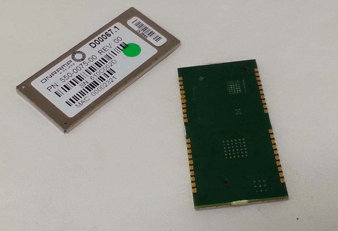
FCC ID XTE‐ULPENODE120 IC: 8655A‐ULPENODE120 Top View (Updated ID label not available during testing) Bottom View
ID Label/Location Info
FCC ID XTE‐ULPENODE120 IC: 8655A‐ULPENODE120
Internal Photos
FCC ID XTE‐ULPENODE120 IC: 8655A‐ULPENODE120
RF Exposure Info
Prediction of MPE limit at a given distance Equation from page 18 of OET Bulletin 65, Edition 97-01where: S = power density P = power input to the antennaG = power gain of the antenna in the direction of interest relative to isotropicR = distance to the center of radiation of the antenna 2 4 R PG S Maximum peak output power at antenna input terminal: 21.79 (dBm) Maximum peak output power at antenna input terminal: 151.01 (mW) Antenna gain(typical): 2 (dBi) Maximum antenna gain: 1.585 (numeric) Prediction distance: 20 (cm) Sourse Based Time Average Duty Cycle: 100 (%) Prediction frequency: 2402 (MHz) MPE limit for uncontrolled exposure at prediction frequency: 1.000 (mW/cm^2) Power density at prediction frequency: 0.0476 (mW/cm^2) Power density at prediction frequency: 0.476 (W/m^2) Margin of Compliance: -13.22 (dB) 2 4 R PG S
Test Report
Report No. SC1108236 September 2011 America Report On Radio Testing of the On‐Ramp Wireless eNode RF Module Model ULPN120 FCC Part 15 Subpart C §15.247 IC RSS‐210 Issue 8 December 2010 FCC ID XTE‐ULPENODE120 IC: 8655A‐ULPENODE120 Report No. SC1108236 REPORT ON TEST REPORT NUMBER Radio Testing of the On‐Ramp Wireless eNode RF Module SC1108236 September 2011 PREPARED FOR On‐Ramp Wireless 10920 Via Frontera. San Diego, CA 92127 PREPARED BY Ferdinand S. Custodio Name Title: EMC/Wireless Test Engineer APPROVED BY Chip R. Fleury Name Authorized Signatory DATED October 3, 2011 FCC ID XTE‐ULPENODE120 IC: 8655A‐ULPENODE120 Report No. SC1108236 Page 3 of 65 CONTENTS Section Page No 1 REPORT SUMMARY ............................................................................................................................ 4 1.1 Introduction .............................................................................................................................................. 5 1.2 Brief Summary Of Results ......................................................................................................................... 6 1.3 Product Information ................................................................................................................................. 7 1.4 EUT Test Configuration ........................................................................................................................... 10 1.5 Deviations From The Standard ................................................................................................................ 12 1.6 Modification Record ............................................................................................................................... 12 1.7 Test Methodology .................................................................................................................................. 12 1.8 Test Facility ............................................................................................................................................. 12 2 TEST DETAILS .................................................................................................................................... 13 2.1 Peak Output Power ................................................................................................................................. 14 2.2 Conducted Emissions .............................................................................................................................. 19 2.3 20 dB Bandwidth .................................................................................................................................... 23 2.4 99% Emission Bandwidth ........................................................................................................................ 26 2.5 Minimum 6 dB RF Bandwidth ................................................................................................................. 29 2.6 Out‐Of‐Band Emissions ‐ Conducted ....................................................................................................... 32 2.7 Band‐Edge Compliance Of Rf Conducted Emissions ................................................................................ 43 2.8 Spurious Radiated Emissions .................................................................................................................. 45 2.9 Power Spectral Density ........................................................................................................................... 54 3 TEST EQUIPMENT USED .................................................................................................................... 59 3.1 Test Equipment Used .............................................................................................................................. 60 3.2 Measurement Uncertainty ..................................................................................................................... 61 4 DIAGRAM OF TEST SETUP ................................................................................................................. 62 4.1 Test Setup Diagram ................................................................................................................................ 63 5 ACCREDITATION, DISCLAIMERS AND COPYRIGHT .............................................................................. 64 5.1 Accreditation, Disclaimers and Copyright ............................................................................................... 65 FCC ID XTE‐ULPENODE120 IC: 8655A‐ULPENODE120 Report No. SC1108236 Page 4 of 65 SECTION 1 REPORT SUMMARY Radio Testing of the On‐Ramp Wireless eNode RF Module FCC ID XTE‐ULPENODE120 IC: 8655A‐ULPENODE120 Report No. SC1108236 Page 5 of 65 1.1 INTRODUCTION The information contained in this report is intended to show verification of the On‐Ramp Wireless eNode RF Module to the requirements of FCC Part 15 Subpart C §15.247 and IC RSS‐210 Issue 8 December 2010. Objective To perform Radio Testing to determine the Equipment Under Test's (EUT’s) compliance with the Test Specification, for the series of tests carried out. Manufacturer On‐Ramp Wireless Model Number(s) ULPN120 FCC ID Number XTE‐ULPENODE120 IC Number 8655A‐ULPENODE120 Serial Number(s) 261B0014 Number of Samples Tested 1 Test Specification/Issue/Date FCC Part 15 Subpart C §15.247 (October 1, 2010). RSS ‐210 ‐ Licence‐exempt Radio Apparatus (All Frequency Bands): Category I Equipment (Issue 8, December 2010). RSS‐Gen ‐ General Requirements and Information for the Certification of Radio Apparatus (Issue 3, December 2010). Start of Test September 19, 2011 Finish of Test September 21, 2011 Name of Engineer(s) Ferdinand S. Custodio Kathy MacKenzie Related Document(s) None. Supporting documents for EUT certification are separate exhibits. FCC ID XTE‐ULPENODE120 IC: 8655A‐ULPENODE120 Report No. SC1108236 1.2 BRIEF SUMMARY OF RESULTS A brief summa…
Text truncated - open the document above for the full version.
Test Setup Photos
FCC ID XTE‐ULPENODE120 IC: 8655A‐ULPENODE120 Conducted Port Test Setup Conducted Emissions Test Setup Radiated Emissions Test Setup (Below 1GHz) Radiated Emissions Test Setup (Above 1GHz)
Contact Information
Applicant
Eber Lambert(SR. DIRECTOR, ENGINEERING PROGRAM MANAGEMENT)
Test Firm
TUV AmericaSteve Dkstra
Technical Specifications
| # | Rule Parts | Frequency Range | Power Output |
|---|---|---|---|
| 1 | 15C | 2.40 GHz - 2.48 GHz | 151.00 mW |
Other Applications from Ingenu
XTE-NODE102
Sep 21, 2015Wireless network module
Equipment Class
DSS - Part 15 Spread Spectrum Transmitter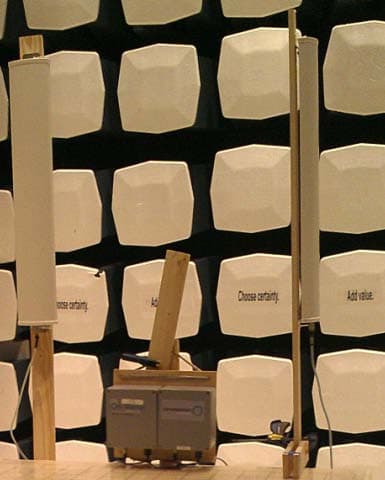
XTE-ULPAP210
May 12, 2015Sectorized RPMA Access Point
Equipment Class
DTS - Digital Transmission System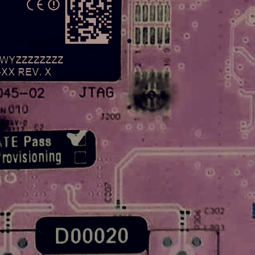
XTE-TRN-2012
Jun 02, 2013Meter Communication Module
Equipment Class
DTS - Digital Transmission System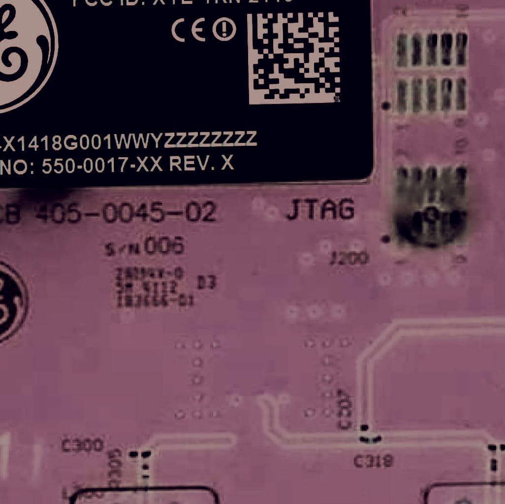
XTE-TRN-2113
Jun 02, 2013Meter Communications Module
Equipment Class
DTS - Digital Transmission System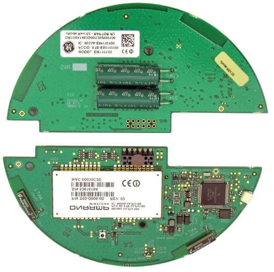
XTE-EM110100
Sep 30, 2012Electric Meter Communications Module
Equipment Class
DSS - Part 15 Spread Spectrum Transmitter