XTS-BT-PTTBT PTT for Two Way Radio
Mobility Sound Technology Ltd.
Click to zoom
Application Details
- Equipment Class
- DSS - Part 15 Spread Spectrum Transmitter
- Date of Grant
- May 17, 2012
- Application Purpose
- Original Equipment
- Date of Application
- May 17, 2012
- Equipment Note
- BT PTT for Two Way Radio
- Frequency Range
- 2402.00000000 - 2480.00000000
- Country
- Taiwan
Documents & Files
Document Text
Text extracted from the exhibit documents filed with the FCC. Open a document above to read the original.
Users Manual
The Mobility Sound Bluetooth PTT BT-PTT allows you to use a compatible BTD adapter with your two-way radio. Version 1.0 October 2010 Bluetooth PTT Model No.: BT-PTT Made in Taiwan FCC ID: XTS-BTD-1M3 CE, RoHS Ready BT-PTT Bluetooth PTT QUICK START 1. Charge the BT-PTT 2. Pair the BT-PTT with a Bluetooth Adapter and wireless headset. 3. Test and Use. Charging the BT-PTT STEP ONE: Charging the BT-PTT The BT-PTT has an internal Lithium Ion rechargeable battery pack which must be charged prior to operation, and must be recharged regularly. A fully charged battery will provide approximately 12 hours (or more) of operation before needing to be recharged. To charge the BT-PTT: * Ensure the BT-PTT is turned on, using the switch located on the back of the device. * Plug the supplied wall charger into an AC (110V) wall outlet. * Plug the charger into charge jack on the bottom of the Bluetooth adapter. You will need to remove the protective rubber cover that is inserted into the charge jack. (To prevent dust and moisture from damaging your PTT, always ensure this cover is in place when you are not charging the BT-PTT.) * The BT-PTT takes approximately 4.5 hours to charge. Actual charge time will vary depending on several factors including the battery’s charge state, condition, and age. Charging Cautions: - Use only the wall charger supplied by the manufacturer. Do not use any other charger. - Do not use a wall charger that appears to be damaged. (Example: frayed wires, melted plastic, etc.) Contact your distributer to get a new manufacturer-approved replacement charger. - Do not tamper with or modify the BT-PTT or charger. STEP TWO: Pairing the BT-PTT In order to operate, the BT-PTT must be paired to Bluetooth Adapter (BTD-xxx series) and Bluetooth headset. To pair these three devices, follow this procedure: * The Bluetooth Adapter must be connected to a compatible radio with a freshly charged battery. Ensure the two-way radio, Bluetooth headset, and BT-PTT are all powered off. * Place the adapter in Accessory Pairing mode. To do this, turn the two-way radio on while holding down the Talk button on the Bluetooth Adapter. Continue to hold the Talk button down for approximately three seconds. Release the Talk button when the status LED flashes two times per second. The Bluetooth Adapter is now in audio accessory pairing mode. * Activate the pairing mode on your Bluetooth headset by following the instructions provided by the headset’s manufacturer. Once the wireless audio accessory and Bluetooth Adapter are paired with each other, the status LED on the adapter will show a constant blue light for three seconds. * Once the headset and adapter have been successfully paired, turn off the two-way radio and Bluetooth headset and wait at least three seconds. * Turn on the two-way radio while holding down the Talk button on the Bluetooth Adapter. Continue to hold the Talk button down for approximately three seconds. Release the Talk button when the status LED flashes two times per second. Then, press the Talk button again. The LED should now flash three times per second, indicating that the adapter is now in BT-PTT Pairing mode. * Place the BT-PTT in pairing mode by holding down the Push-To-Talk button while moving the power switch to the On position. The LED will flash twice in one second. Once the Bluetooth Adapter and BT-PTT are paired with each other, the status LED on the adapter will show a constant blue light for three seconds and the LED on the PTT will show one time per 4 seconds. * If the Bluetooth Adapter or BT- PTT does not detect a compatible wireless accessory within 60 seconds of being put into pairing mode, the devices will exit the pairing mode and resume normal operation. * After pairing is successful, turn off the BT-PTT and the two-way radio that the Bluetooth Adapter is attached. Wait at least three seconds. STEP THREE: Testing and Using the BT-PTT After the Bluetooth headset, Bluetooth Adapter and BT-PTT have been paired with each other you can test and use them together: * Turn on the two-way radio the Bluetooth Adapter is connected to. * Turn on the Bluetooth headset. Within a few seconds the LED indicator on the adapter should show a long flash, indicating the headset and adapter are connected. * Turn on the BT-PTT. Within a few seconds the LED indicator on the adapter should show a long flash, indicating the headset and adapter are connected. The LED on the PTT should also flash per 4 seconds. *You will now be able to operate using the wireless accessories. Pressing the Push-to-Talk button on the BT-PTT will cause the two-way radio to transmit. Transmit audio will be picked up by the Bluetooth headset. Received signals will also be heard through the Bluetooth headset’s earphone. ----------------------------------------------------------------- Note: You can follow these Pairing step if pairing difficult 1) Let BT-Headset in pairing mode 2) Connect BTD-XXX to radio and let the Dongle in pairing mode (2 flash/S) 3) Paired the BTD-XXX with BT-Headset 4) Close BT-Headset (important) 5) Close radio and push BTD-XXX PTT to let BTD-XXX in pairing mode and push PTT again, Let Dongle in BT-PTT pairing mode.(3 flash/S) 6) Let BT-PTT in pairing mode. (2 flash/S) 7) Paired Dongle with BT-PTT. 8) Power on BT-Headset.(important). BT-PTT won’t work if BT-Headset is off. 9) After BT-Headset link with Dongle then you can use BT-PTT. BLUETOOTH PTT USER’S GUIDE For Compatible Wireless Audio Accessories STATUS LED MESSAGES The meanings of the various status LED messages shown by the BT-PTT are shown on the following table: LED Indication Meaning Long blue flash PTT Powered On (Disconnection / Unpaired) One blue flash every 4 seconds Normal (Paired) operation Two blue flashes every second Pairing Mode Red Push-to-Talk activated Long blue flash Lost connection / Unpaired operation One blue flash every 1 seconds Powered On +Low battery Blue Powered On +Charging All led off Powered On +Charging complete Lon…
Text truncated - open the document above for the full version.
External Photos
Report No.: 120305E03A 1 Report Format Version 4.0.0 Reference No.: 120503E04 CONSTRUCTION PHOTOS OF EUT 廠牌: Mobility Sound, 型號: BT-PTT Report No.: 120305E03A 6 Report Format Version 4.0.0 Reference No.: 120503E04 Report No.: 120305E03A 7 Report Format Version 4.0.0 Reference No.: 120503E04
ID Label/Location Info
FCC ID: XTS-BT-PTT LABEL LOCATION The label will be permanently affixed at a conspicuous location on the device. Label Here
Internal Photos
Report No.: 120305E03A 2 Report Format Version 4.0.0 Reference No.: 120503E04 Report No.: 120305E03A 3 Report Format Version 4.0.0 Reference No.: 120503E04 Report No.: 120305E03A 4 Report Format Version 4.0.0 Reference No.: 120503E04 Report No.: 120305E03A 5 Report Format Version 4.0.0 Reference No.: 120503E04
Operational Description
FCC ID: XTS-BT-PTT Report No.: RF120305E03A Reference No.: 120503E04 Operational Description This device is a BT PTT for Two Way Radio. The transmitter of the EUT is powered by DC 4.2V from battery or DC 5V from host equipment. The antenna is Chip antenna without antenna connector. For more detailed instruction, please take a look at the user’s manual. FCC ID: XTS-BT-PTT Report No.: RF120305E03A Reference No.: 120503E04 Operational Description This device is a BT PTT for Two Way Radio. The transmitter of the EUT is powered by DC 4.2V from battery or DC 5V from host equipment. The antenna is Chip antenna without antenna connector. For more detailed instruction, please take a look at the user’s manual.
RF Exposure Info
Report No.: SA120305E03B Report Format Version 4.0.0 Reference No.: 120504E05 1 RF EXPOSURE REPORT REPORT NO.: SA120305E03B MODEL NO.: BT-PTT FCC ID: XTS-BT-PTT RECEIVED: Mar. 05, 2012 TESTED: Apr. 12, 2012 ISSUED: May 09, 2012 APPLICANT: Mobility Sound Technology Ltd. ADDRESS: 5F., No.100, Jian 1st Rd., Zhonghe Dist., New Taipei City 235, Taiwan (R.O.C.) ISSUED BY: Bureau Veritas Consumer Products Services (H.K.) Ltd., Taoyuan Branch Hsin Chu Laboratory LAB ADDRESS: No. 81-1, Lu Liao Keng, 9th Ling,Wu Lung Tsuen, Chiung Lin Hsiang, Hsin Chu Hsien 307, Taiwan, R.O.C. This test report consists of 5 pages in total. It may be duplicated completely for legal use with the approval of the applicant. It should not be reproduced, except in full, without the written approval of our laboratory. The client should not use it to claim product certification, approval or endorsement by any government agency. The test results in the report only apply to the tested sample. Report No.: SA120305E03B Report Format Version 4.0.0 Reference No.: 120504E05 2 TABLE OF CONTENTS RELEASE CONTROL RECORD .................................................................................... 3 1. CERTIFICATION .............................................................................................. 4 2. EVALUATION RESULT ................................................................................... 5 Report No.: SA120305E03B Report Format Version 4.0.0 Reference No.: 120504E05 3 RELEASE CONTROL RECORD ISSUE NO. REASON FOR CHANGE DATE ISSUED SA120305E03B Original release May 09, 2012 Report No.: SA120305E03B Report Format Version 4.0.0 Reference No.: 120504E05 4 1. CERTIFICATION PRODUCT: BT PTT for Two Way Radio BRAND: Mobility Sound MODEL: BT-PTT TEST SAMPLE: ENGINEERING SAMPLE APPLICANT: Mobility Sound Technology Ltd. TESTED: Apr. 12, 2012 STANDARDS: IEEE C95.1 The above equipment (Model: BT-PTT) has been tested by Bureau Veritas Consumer Products Services (H.K.) Ltd., Taoyuan Branch, and found compliance with the requirement of the above standards. The test record, data evaluation & Equipment Under Test (EUT) configurations represented herein are true and accurate accounts of the measurements of the sample’s EMC characteristics under the conditions specified in this report. PREPARED BY : , DATE: Mar. 19, 2012 ( Lori Chung, Specialist ) APPROVED BY : , DATE: Mar. 19, 2012 ( May Chen, Deputy Manager ) Report No.: SA120305E03B Report Format Version 4.0.0 Reference No.: 120504E05 5 2. EVALUATION RESULT No SAR Evaluation Required if power is below the following threshold: Tunable Range F(GHz) Low F(GHz) High 60/f SAR Limitation (mW) 2.402 2.480 24.19 Maximum measured transmitter power: Pout Conducted (dBm) Pout Conducted (mW) Maximum Antenna Gain (dBi) Pout EIRP (mW) 5.37 3.443 -0.5 3.069 Threshold for no SAR evaluation is 24.19 mW Maximum TX Power is 1.016 mW Conducted and 3.069 mW EIRP Conclusion: No SAR evaluation required since maximum Transmitter Pout (both conducted and EIRP) is below FCC threshold --- END ---
Test Report
Report No.: RF120305E03A 1 Report Format Version 4.2.0 Reference No.: 120503E04 FCC TEST REPORT REPORT NO.: RF120305E03A MODEL NO.: BT-PTT FCC ID: XTS-BT-PTT RECEIVED: Mar. 05, 2012 TESTED: Apr. 12 to 18, 2012 ISSUED: May 09, 2012 APPLICANT: Mobility Sound Technology Ltd. ADDRESS: 5F., No.100, Jian 1st Rd., Zhonghe Dist., New Taipei City 235, Taiwan (R.O.C.) ISSUED BY: Bureau Veritas Consumer Products Services (H.K.) Ltd., Taoyuan Branch Hsin Chu Laboratory LAB ADDRESS: No. 81-1, Lu Liao Keng, 9th Ling,Wu Lung Tsuen, Chiung Lin Hsiang, Hsin Chu Hsien 307, Taiwan, R.O.C. TEST LOCATION (1): No. 81-1, Lu Liao Keng, 9th Ling,Wu Lung Tsuen, Chiung Lin Hsiang, Hsin Chu Hsien 307, Taiwan, Taiwan, R.O.C. TEST LOCATION (2): No.49, Ln. 206, Wende Rd., Shangshan Tsuen, Chiung Lin Hsiang, Hsin Chu Hsien 307, Taiwan, Taiwan, R.O.C. This test report consists of 59 pages in total. It may be duplicated completely for legal use with the approval of the applicant. It should not be reproduced except in full, without the written approval of our laboratory. The client should not use it to claim product certification, approval, or endorsement by TAF or any government agencies. The test results in the report only apply to the tested sample. Report No.: RF120305E03A 2 Report Format Version 4.2.0 Reference No.: 120503E04 TABLE OF CONTENTS RELEASE CONTROL RECORD ........................................................................................................ 4 1 CERTIFICATION ................................................................................................................ 5 2 SUMMARY OF TEST RESULTS ......................................................................................... 6 2.1 ME ASUREMENT UNCERTAINTY ..................................................................................... 7 3 GENERAL INFORMATION ................................................................................................. 8 3.1 GENERAL DESCRIPTION OF EUT .................................................................................... 8 3.2 DESCRIPTION OF TEST MODES ...................................................................................... 9 3.3 TEST MODE APPLICABLITY AND TESTED CHANNEL DETAIL: ......................................10 3.4 GENERAL DESCRIPTION OF APPLIED STANDARDS .....................................................12 3.5 DESCRIPTION OF SUPPORT UNITS ...............................................................................13 3.6 CONFIGURATION OF SYSTEM UNDER TEST.................................................................13 4 TEST PROCEDURES AND RESULTS ..............................................................................14 4.1 CONDUCTED EMISSION MEASUREMENT .....................................................................14 4.1.1 LIMITS OF CONDUCTED EMISSION MEASUREMENT....................................................14 4.1.2 TEST INSTRUMENTS .......................................................................................................14 4.1.3 TEST PROCEDURES .......................................................................................................15 4.1.4 TEST SETUP ....................................................................................................................15 4.1.5 EUT OPERATING CONDITIONS .......................................................................................15 4.1.6 TEST RESULTS ................................................................................................................16 4.2 RADIATED EMISSION AND BANDEDGE MEASUREMENT ..............................................18 4.2.1 LIMITS OF RADIATED EMISSION AND BANDEDGE MEASUREMENT ............................18 4.2.2 TEST INSTRUMENTS .......................................................................................................19 4.2.3 TEST PROCEDURES .......................................................................................................20 4.2.4 DEVIATION FROM TEST STANDARD ..............................................................................20 4.2.5 TEST SETUP ....................................................................................................................21 4.2.6 EUT OPERATING CONDITIONS .......................................................................................21 4.2.7 TEST RESULTS ................................................................................................................22 4.3 NUMBER OF HOPPING FREQUENCY USED ..................................................................29 4.3.1 LIMIT OF HOPPING FREQUENCY USED .........................................................................29 4.3.2 TEST INSTRUMENTS .......................................................................................................29 4.3.3 TEST PROCEDURES .......................................................................................................29 4.3.4 DEVIATION FROM TEST STANDARD ..............................................................................29 4.3.5 TEST SETUP ....................................................................................................................30 4.3.6 TEST RESULTS ................................................................................................................30 4.4 DWELL TIME ON EACH CHANNEL ..................................................................................33 4.4.1 LIMIT OF DWELL TIME USED ..........................................................................................33 4.4.2 TEST INSTRUMENTS .......................................................................................................33 4.4.3 TEST PROCEDURES .......................................................................................................33 4.4.4 DEVIATION FROM TEST STANDARD ..............................................................................34…
Text truncated - open the document above for the full version.
Test Setup Photos
Report No.: 120305E03A 1 Report Format Version 4.2.0 Reference No.: 120503E04 PHOTOGRAPHS OF THE TEST CONFIGURATION CONDUCTED EMISSION TEST Report No.: 120305E03A 2 Report Format Version 4.2.0 Reference No.: 120503E04 RADIATED EMISSION TEST (Below 1GHz) Report No.: 120305E03A 3 Report Format Version 4.2.0 Reference No.: 120503E04 RADIATED EMISSION TEST (Above 1GHz) Report No.: 120305E03A 4 Report Format Version 4.2.0 Reference No.: 120503E04
Contact Information
Applicant
CC Chuang(General Manager)
Technical Contact
Bureau Veritas CPS (H.K.) Ltd. Taoyuan BranchHank Chung
[email protected]886-3-593-5343
Bureau Veritas CPS (H.K.) Ltd. Taoyuan Branch · Hsinchu Hsien · Taiwan
Non-Technical Contact
Bureau Veritas CPS (H.K.) Ltd. Taoyuan BranchAmanda Chu
[email protected]886-3-593-5343
Test Firm
Bureau Veritas CPS (H.K.) Ltd. Taoyuan BranchRichard Chen
Technical Specifications
| # | Rule Parts | Frequency Range | Power Output |
|---|---|---|---|
| 1 | 15C | 2.40 GHz - 2.48 GHz | 3.00 mW |
Other Applications from Mobility Sound Technology Ltd.
XTS-FP2
Sep 21, 2022Bluetooth LE scanner trigger
Equipment Class
DXX - Part 15 Low Power Communication Device Transmitter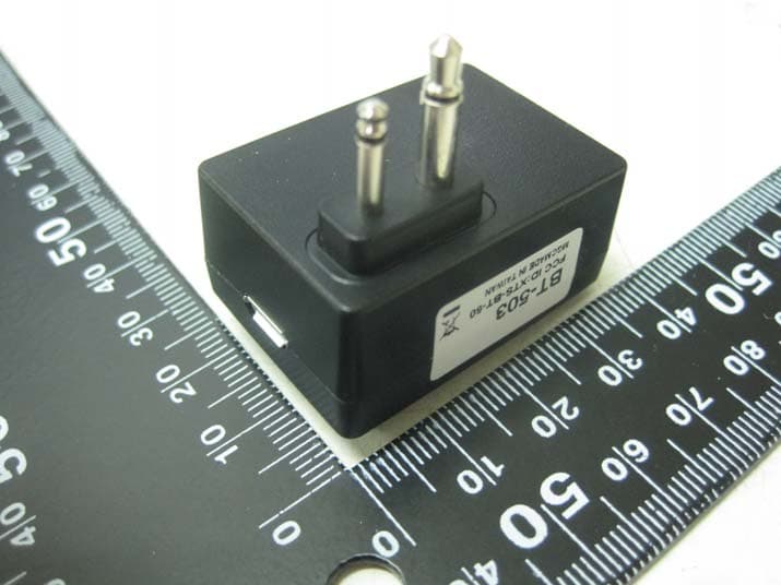
XTS-BT-503
Mar 01, 2021Bluetooth Dongle
Equipment Class
DXX - Part 15 Low Power Communication Device Transmitter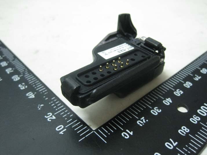
XTS-BT-523
Feb 24, 2021Bluetooth Dongle
Equipment Class
DXX - Part 15 Low Power Communication Device Transmitter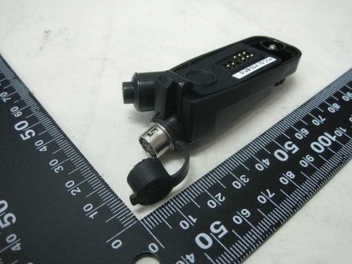
XTS-BT-5
Feb 24, 2021Bluetooth Dongle
Equipment Class
DXX - Part 15 Low Power Communication Device Transmitter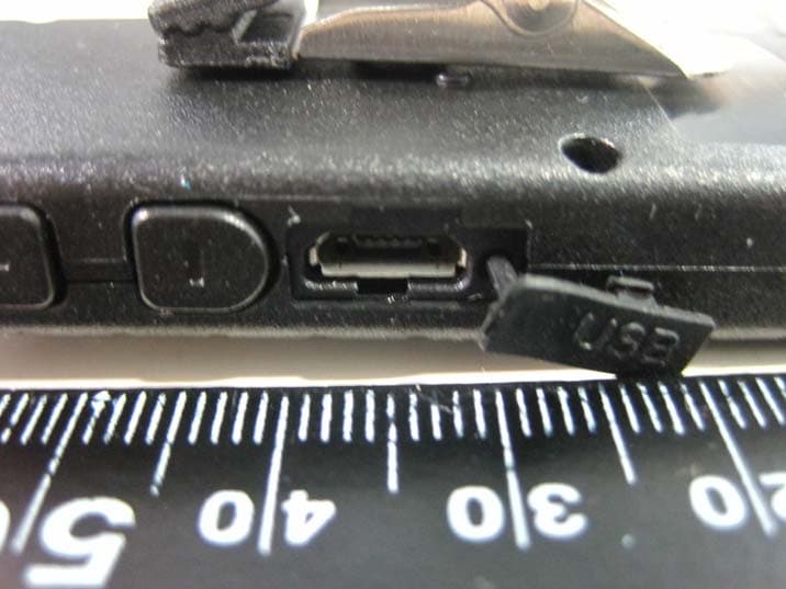
XTS-BTH-300
Aug 31, 2015Bluetooth Headset
Equipment Class
DSS - Part 15 Spread Spectrum Transmitter