XTX-110Ez Care
LiveFree Emergency Response, Inc.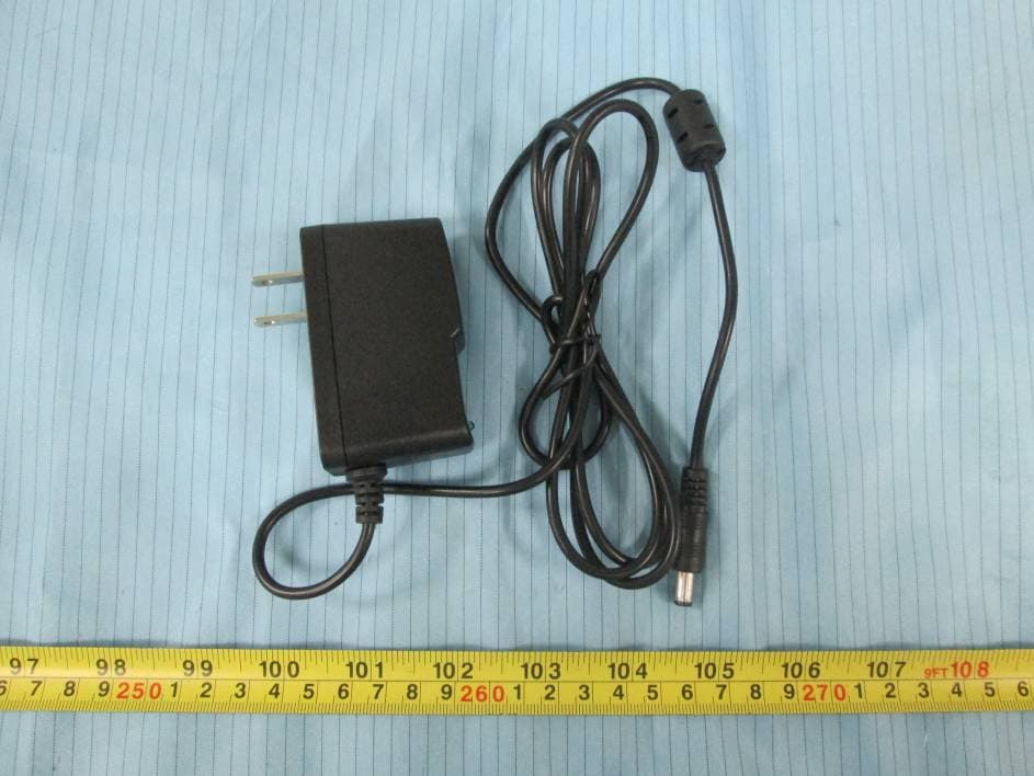
Click to zoom
Application Details
- Equipment Class
- CYY - Communications Receiver used w/Pt 15 Transmitter
- Date of Grant
- Dec 17, 2015
- Application Purpose
- Original Equipment
- Date of Application
- Dec 17, 2015
- Equipment Note
- Ez Care
- Frequency Range
- 315.00000000 - 315.00000000
- Country
- United States
Documents & Files
Document Text
Text extracted from the exhibit documents filed with the FCC. Open a document above to read the original.
Users Manual
User Manual 1. Make SOS emergency call : Press and hold the red SOS button on the base station or the button on the RF pendant to make a test call 2. Hang up or cancel Press and hold the red SOS button on the base station for 3 seconds to hang up the call or cancel dialing 3. Fix‐time‐call function on/off: switch button can turn on/off the Fix‐time‐call function. 4. The base station can pair RF devices to it; after paired, when RF device activated, it activated base station to make a call. FCC Caution: Any Changes or modifications not expressly approved by the party responsible for compliance could void the user's authority to operate the equipment. This device complies with part 15 of the FCC Rules. Operation is subject to the following two conditions: (1) This device may not cause harmful interference, and (2) this device must accept any interference received, including interference that may cause undesired operation. Note: This equipment has been tested and found to comply with the limits for a Class B digital device, pursuant to part 15 of the FCC Rules. These limits are designed to provide reasonable protection against harmful interference in a residential installation. This equipment generates, uses and can radiate radio frequency energy and, if not installed and used in accordance with the instructions, may cause harmful interference to radio communications. However, there is no guarantee that interference will not occur in a particular installation. If this equipment does cause harmful interference to radio or television reception, which can be determined by turning the equipment off and on, the user is encouraged to try to correct the interference by one or more of the following measures: —Reorient or relocate the receiving antenna. —Increase the separation between the equipment and receiver. —Connect the equipment into an outlet on a circuit different from that to which the receiver is connected. —Consult the dealer or an experienced radio/TV technician for help. Customer Information 1. This equipment complies with Part 68 of the FCC rules and the requirements adopted by the ACTA. On the bottom of this equipment is a label that contains, among other information, a product identifier in the format US: AAAEQ##TXXXX. If requested, this number must be provided to the telephone company. 2. A plug and jack used to connect this equipment to the premises wiring and telephone network must comply with the applicable FCC Part 68 rules and requirements adopted by the ACTA. A compliant telephone cord and modular plug is provided with this product. It is designed to be connected to a compatible modular jack that is also compliant. See installation instructions for details. 3. If this equipment [US: PNYAL06BXTX110] causes harm to the telephone network, the telephone company will notify you in advance that temporary discontinuance of service may be required. But if advance notice isn't practical, the telephone company will notify the customer as soon as possible. Also, you will be advised of your right to file a complaint with the FCC if you believe it is necessary. 4. The telephone company may make changes in its facilities, equipment, operations or procedures that could affect the operation of the equipment. If this happens the telephone company will provide advance notice in order for you to make necessary modifications to maintain uninterrupted service. 5. If trouble is experienced with this equipment [US: PNYAL06BXTX110], for repair or warranty information, Service can be facilitated through our office at: U.S. Agent Company name: LiveFree Emergency Response, Inc. Address: 3780 Woodhaven Lane, Idaho Falls, Idaho, 83404 USA Tel: 2082203817 Fax: 8014574890 If the equipment is causing harm to the telephone network, the telephone company may request that you disconnect the equipment until the problem is resolved. 6. Please follow instructions for repairing if any (e.g. battery replacement section); otherwise do not alternate or repair any parts of device except specified. 7. Connection to party line service is subject to state tariffs. Contact the state public utility commission, public service commission or corporation commission for information. 8. If your home has specially wired alarm equipment connected to the telephone line, ensure the installation of this [AL] does not disable your alarm equipment. If you have questions about what will disable alarm equipment, consult your telephone company or a qualified installer. 9. If the telephone company requests information on what equipment is connected to their lines, inform them of: a) The ringer equivalence number [0.6B] b) The USOC jack required [RJ11C] c) Facility Interface Codes (“FIC”) [02LS2] d) Service Order Codes (“SOC”) [9.0Y] e) The FCC Registration Number [US: PNYAL06BXTX110] 10. The REN is used to determine the number of devices that may be connected to a telephone line. Excessive RENs on a telephone line may result in the devices not ringing in response to an incoming call. In most but not all areas, the sum of RENs should not exceed five (5.0). To be certain of the number of devices that may be connected to a line, as determined by the total RENs, contact the local telephone company. The REN for this product is part of the product identifier that has the format US:AAAEQ##TXXXX. The digits represented by ## are the REN without a decimal point. For this product the FCC Registration number is [US: PNYAL06BXTX110] indicates the REN would be 0.6B. 11. If this product is equipped with a corded or cordless handset, it is hearing aid compatible.
External Photos
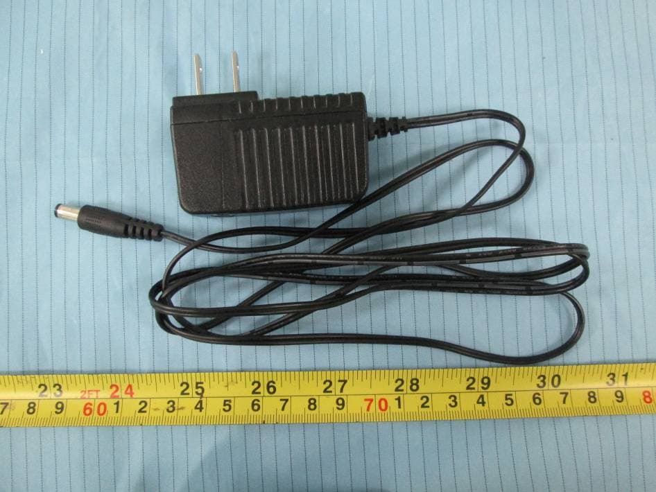
EXHIBIT B - EUT EXTERNAL PHOTOGRAPHS EUT – Front View EUT – Rear View EUT – Top View EUT – Bottom View EUT – Left Side View EUT – Right Side View EUT – Adapter View EUT – Adapter Label View
ID Label/Location Info
EXHIBIT A - FCC ID LABEL AND LOCATION FCC ID Label FCC ID Label Location Information The label shown shall be permanently affixed at a conspicuous location on the device and be readily visible to the user at the time purchase (Labeling requirements per 2.925)
Internal Photos
EXHIBIT C - EUT INTERNAL PHOTOGRAPHS EUT –Cover off View EUT – Main Board 1 Top View Antenna EUT – Main Board 1 Bottom View EUT – Main Board 2 Top View EUT – Main Board 2 Bottom View EUT –Rearboard Top View EUT –Rearboard Bottom View EUT –IC 1 View EUT –IC 2 View
Test Report
Note: This test report is prepared for the customer shown above and for the device described herein. It may not be duplicated or used in part without prior written consent from Bay Area Compliance Laboratories Corp. FCC PART 15B, CLASS B TEST REPORT For LiveFree Emergency Response, Inc. 3780 Woodhaven Lane, Idaho Falls, Idaho United States FCC ID: XTX-110 Report Type: Original Report Product Type: Ez care Test En gineer: Mike Hu Re port Number: RSZ151022014-00 Re port Date: 2015-11-04 Reviewed B y: Bell Hu RF Engineer Prepared By: Bay Area Compliance Laboratories Corp. (Shenzhen) 6/F, the 3rd Phase of WanLi Industrial Building ShiHua Road, FuTian Free Trade Zone Shenzhen, Guangdong, China Tel: +86-755-33320018 Fax: +86-755-33320008 www.baclcorp.com.cn Bay Area Compliance Laboratories Corp. (Shenzhen) Report No.: RSZ151022014-00 FCC Part 15B, Class B Page 2 of 15 TABLE OF CONTENTS GENERAL INFORMATION ....................................................................................................................................... 3 PRODUCT DESCRIPTION FOR EQUIPMENT UNDER TEST (EUT) ..................................................................................... 3 OBJECTIVE ................................................................................................................................................................... 3 RELATED SUBMITTAL(S)/GRANT(S) ............................................................................................................................. 3 TEST FACILITY ............................................................................................................................................................. 3 SYSTEM TEST CONFIGURATION .......................................................................................................................... 4 DESCRIPTION OF TEST CONFIGURATION ...................................................................................................................... 4 EUT EXERCISE SOFTWARE .......................................................................................................................................... 4 SPECIAL ACCESSORIES ................................................................................................................................................. 4 EQUIPMENT MODIFICATIONS ....................................................................................................................................... 4 SUPPORT EQUIPMENT LIST AND DETAILS .................................................................................................................... 4 EXTERNAL I/O CABLE .................................................................................................................................................. 4 BLOCK DIAGRAM OF TEST SETUP ................................................................................................................................ 5 SUMMARY OF TEST RESULTS ............................................................................................................................... 6 FCC §15.107 – AC LINE CONDUCTED EMISSIONS ............................................................................................. 7 APPLICABLE STANDARD .............................................................................................................................................. 7 MEASUREMENT UNCERTAINTY .................................................................................................................................... 7 EUT SETUP .................................................................................................................................................................. 7 EMI TEST RECEIVER SETUP ......................................................................................................................................... 8 TEST PROCEDURE ........................................................................................................................................................ 8 TEST EQUIPMENT LIST AND DETAILS ........................................................................................................................... 8 CORRECTED FACTOR & MARGIN CALCULATION ......................................................................................................... 8 TEST RESULTS SUMMARY ............................................................................................................................................ 9 TEST DATA .................................................................................................................................................................. 9 FCC §15.109 - RADIATED SPURIOUS EMISSIONS ............................................................................................ 12 APPLICABLE STANDARD ............................................................................................................................................ 12 MEASUREMENT UNCERTAINTY .................................................................................................................................. 12 EUT SETUP ................................................................................................................................................................ 12 EMI TEST RECEIVER SETUP ....................................................................................................................................... 13 TEST PROCEDURE ...................................................................................................................................................... 13 TEST EQUIPMENT LIST AND DETAILS ......................................................................................................................... 13 CORRECTED AMPLITUDE & MARGIN CALCULATION ..........................................................................................…
Text truncated - open the document above for the full version.
Test Setup Photos
EXHIBIT D - TEST SETUP PHOTOGRAPHS Conducted Emissions - Front View Conducted Emissions - Side View Radiated Emissions – Front View (Below 1 GHz) Radiated Emissions – Rear View (Below 1 GHz) Radiated Emissions – Front View (Above 1 GHz) Radiated Emissions – Rear View (Above 1 GHz)
Contact Information
Applicant
Joshua Chandler(President)
Test Firm
Bay Area Compliance Laboratory Corp. (Shenzhen)John Chan
Technical Specifications
| # | Rule Parts | Frequency Range | Power Output |
|---|---|---|---|
| 1 | 15B | 315 MHz - 315 MHz | - |
Other Applications from LiveFree Emergency Response, Inc.
XTX-EZV
Nov 03, 2015EZC
Equipment Class
PCB - PCS Licensed Transmitter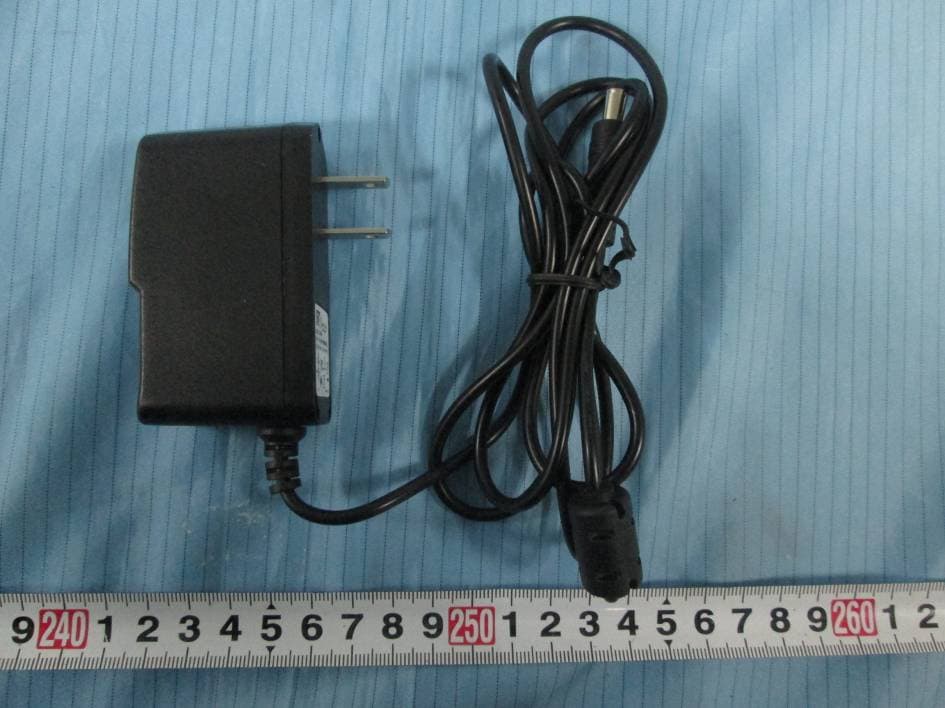
XTX-EZC
Feb 17, 2015Fixed Wireless Phone
Equipment Class
JBP - Part 15 Class B Computing Device Peripheral
XTX-100
Feb 21, 2013EZ CARE
Equipment Class
CYY - Communications Receiver used w/Pt 15 Transmitter
XTX-LF500
Mar 07, 2011GPS Watch Tracker
Equipment Class
PCB - PCS Licensed Transmitter