XTX-EZVEZC
LiveFree Emergency Response, Inc.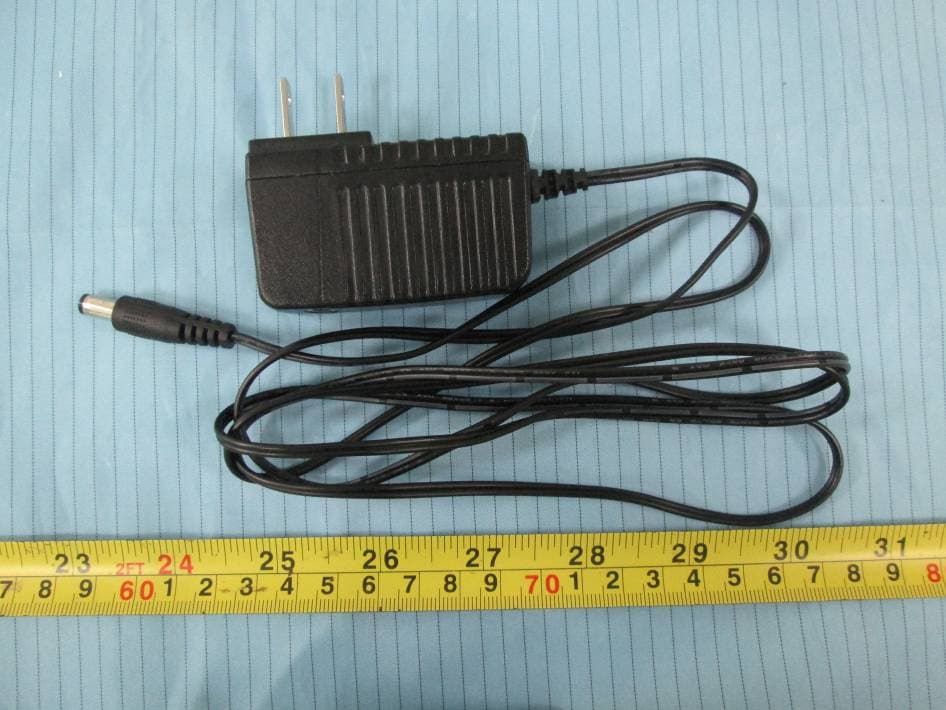
Click to zoom
Application Details
- Equipment Class
- PCB - PCS Licensed Transmitter
- Date of Grant
- Nov 03, 2015
- Application Purpose
- Original Equipment
- Date of Application
- Nov 03, 2015
- Equipment Note
- EZC
- Frequency Range
- 1851.25000000 - 1908.75000000
- Country
- United States
Documents & Files
Document Text
Text extracted from the exhibit documents filed with the FCC. Open a document above to read the original.
Users Manual
User manual 1. Photo 2. Instructions (1)Connect the power adaptor to the device then connect to wall charger (2) Switch on the on/off button to turn on the device (3) Activated SOS button to call to a preset phone number to get help from center. (4) Activated family button to call to a preset phone number to a family one. (5) Press hang up button to cancel a dialing or hang up a phone call. 3. FCC Warning Any Changes or modifications not expressly approved by the party responsible for compliance could void the user's authority to operate the equipment. This device complies with part 15 of the FCC Rules. Operation is subject to the following two conditions: (1) This device may not cause harmful interference, and (2) this device must accept any interference received, including interference that may cause undesired operation. This equipment complies with FCC radiation exposure limits set forth for an uncontrolled environment .This equipment should be installed and operated with minimum distance 20cm between the radiator& your body. This transmitter must not be co-located or operating in conjunction with any other antenna or transmitter. Note: This equipment has been tested and found to comply with the limits for a Class B digital device, pursuant to part 15 of the FCC Rules. These limits are designed to provide reasonable protection against harmful interference in a residential installation. This equipment generates, uses and can radiate radio frequency energy and, if not installed and used in accordance with the instructions, may cause harmful interference to radio communications. However, there is no guarantee that interference will not occur in a particular installation. If this equipment does cause harmful interference to radio or television reception, which can be determined by turning the equipment off and on, the user is encouraged to try to correct the interference by one or more of the following measures: —Reorient or relocate the receiving antenna. —Increase the separation between the equipment and receiver. —Connect the equipment into an outlet on a circuit different from that to which the receiver is connected. —Consult the dealer or an experienced radio/TV technician for help.
Cover Letter(s)
LiveFree Emergency Response, Inc. 3780 Woodhaven Lane, Idaho Falls, Idaho, United States Tel: 208-521-2863 Fax: 801-457-4890 FCC Confidential Authorization 2015-10-28 FEDERAL COMMUNICATIONS COMMISSIONS Authorization and Evaluation Division 7435 Oakland Mills Road Columbia, MD 21046 Subject: Confidentiality Request regarding application for certification of FCC ID: XTX-EZV In accordance with Sections 0.457 and 0.459 of the Commission’s Rules, (LiveFree Emergency Response, Inc.) hereby requests long-term confidential treatment of information accompanying this application as outlined below: Block Diagram Schematics Operation Description Parts List/Tune up procedure (for licensed devices) The above materials contain proprietary and confidential information not customarily released to the public. The public disclosure of these materials provides unjustified benefits to its competitors in the market. Sincerely Yours, Signature: Joshua Chandler President
External Photos
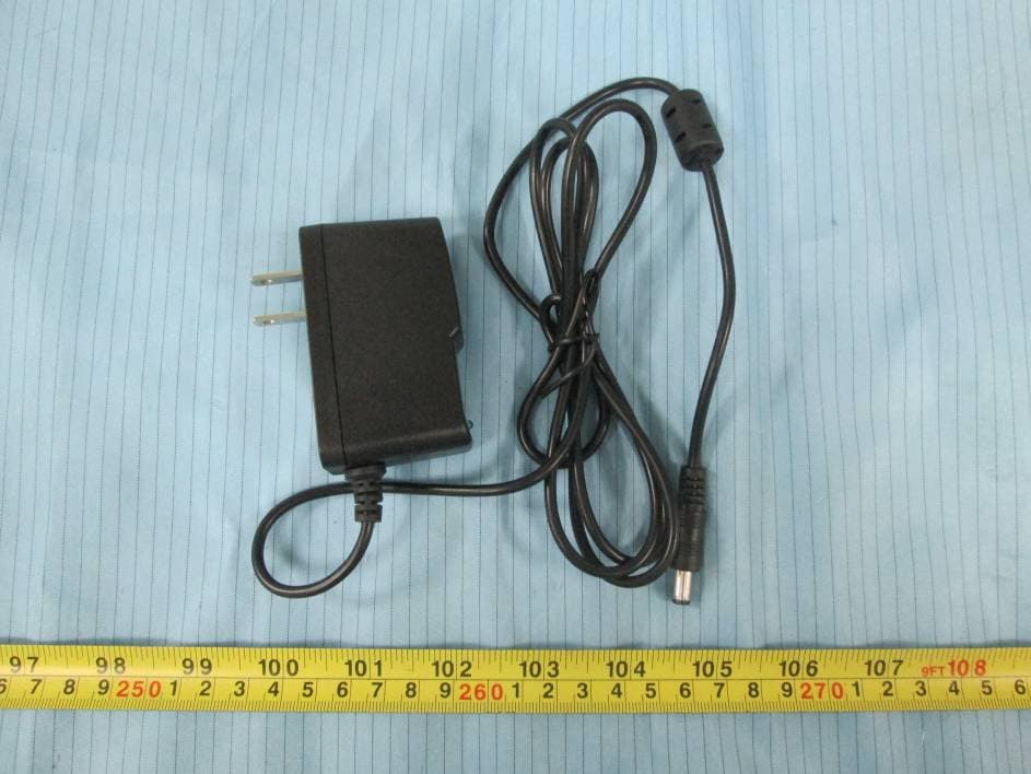
EXHIBIT B - EUT EXTERNAL PHOTOGRAPHS EUT – Front View EUT – Rear View EUT – Top View EUT – Bottom View EUT – Left Side View EUT – Right Side View EUT – Adapter View EUT – Adapter Label View
ID Label/Location Info
EXHIBIT A - FCC ID LABEL AND LOCATION FCC ID Label FCC ID Label Location Information The label shown shall be permanently affixed at a conspicuous location on the device and be readily visible to the user at the time purchase (Labeling requirements per 2.925)
Internal Photos
EXHIBIT C - EUT INTERNAL PHOTOGRAPHS EUT –Cover off View EUT – Main Board 1 Top View Antenna EUT – Main Board 1 Bottom View EUT – Main Board 2 Top View EUT – Main Board 2 Bottom View EUT – Main Board 3 Top View EUT – Main Board 3 Top Shielding off View EUT – Main Board 3 Bottom View EUT – Battery View EUT –Battery Label View
Test Report
Note: This test report is prepared for the customer shown above and for the device described herein. It may not be duplicated or used in part without prior written consent from Bay Area Compliance Laboratories Corp. FCC PART 22H, PART 24E TEST REPORT For LiveFree Emergency Response, Inc. 3780 Woodhaven Lane, Idaho Falls, Idaho United States FCC ID: XTX-EZV Report Type: Original Report Product Type: EZC Test Engineer: Mike Hu Re port Number: RSZ151014002-00B Re port Date: 2015-10-21 Reviewed B y: Jimmy Xiao RF En gineer Prepared By: Bay Area Compliance Laboratories Corp. (Shenzhen) 6/F, the 3rd Phase of WanLi Industrial Building ShiHua Road, FuTian Free Trade Zone Shenzhen, Guangdong, China Tel: +86-755-33320018 Fax: +86-755-33320008 www.baclcorp.com.cn Bay Area Compliance Laboratories Corp. (Shenzhen) Report No.: RSZ151014002-00B FCC Part 22H/24E Page 2 of 10 TABLE OF CONTENTS GENERAL INFORMATION ....................................................................................................................................... 3 PRODUCT DESCRIPTION FOR EQUIPMENT UNDER TEST (EUT) ..................................................................................... 3 OBJECTIVE ................................................................................................................................................................... 3 RELATED SUBMITTAL(S)/GRANT(S) ............................................................................................................................. 3 TEST METHODOLOGY .................................................................................................................................................. 3 TEST FACILITY ............................................................................................................................................................. 4 SYSTEM TEST CONFIGURATION .......................................................................................................................... 5 DESCRIPTION OF TEST CONFIGURATION ...................................................................................................................... 5 EQUIPMENT MODIFICATIONS ....................................................................................................................................... 5 SUPPORT EQUIPMENT LIST AND DETAILS .................................................................................................................... 5 EXTERNAL I/O CABLE .................................................................................................................................................. 5 BLOCK DIAGRAM OF TEST SETUP ................................................................................................................................ 5 SUMMARY OF TEST RESULTS ............................................................................................................................... 6 FCC §1.1307 & §2.1091- MAXIMUM PERMISSIBLE EXPOSURE (MPE) ............................................................. 7 APPLICABLE STANDARD .............................................................................................................................................. 7 TEST DATA .................................................................................................................................................................. 7 FCC §2.1047 - MODULATION CHARACTERISTIC .............................................................................................. 8 FCC §2.1053, §22.917 & §24.238 - SPURIOUS RADIATED EMISSIONS ............................................................. 9 APPLICABLE STANDARD .............................................................................................................................................. 9 TEST PROCEDURE ........................................................................................................................................................ 9 TEST EQUIPMENT LIST AND DETAILS ........................................................................................................................... 9 TEST DATA ................................................................................................................................................................ 10 Bay Area Compliance Laboratories Corp. (Shenzhen) Report No.: RSZ151014002-00B FCC Part 22H/24E Page 3 of 10 GENERAL INFORMATION Product Description for Equipment under Test (EUT) The LiveFree Emergency Response, Inc.’s product, model number: EZcare Plus (FCC ID: XTX-EZV) or the "EUT" in this report was a EZC, which was measured approximately: 21.0 cm (L) x 14.0 cm (W) x 3.6 cm (H), rated with input voltage: DC 3.7 V rechargeable Li-ion battery or DC 5.0 V from adapter. Adapter Information: Model: JF012WR-0500200UV Input: AC 100-240V, 50/60Hz, 0.35A Output: DC 5.0V, 2A *All measurement and test data in this report was gathered from production sample serial number: 1506802 (Assigned by Shenzhen BACL). The EUT supplied by the applicant was received on 2015-10-14. Objective This test report is prepared on behalf of LiveFree Emergency Response, Inc. in accordance with Part 2- Subpart J, Part 22-Subpart H and Part 24-Subpart E of the Federal Communication Commissions rules. The objective is to determine the compliance of the EUT with FCC rules for output power, modulation characteristic, occupied bandwidth, and spurious emission at antenna terminal, spurious radiated emission, frequency stability and band edge. Related Submittal(s)/Grant(s) FCC Part 15B CYY submissions with FCC ID: XTX-EZV Test Methodology All tests and measurements indicated in this document were performed in accordance with the Code of Federal Regulations Title 47 Part 2-Subpart J as well as the following parts: Part 22 Subpart H - Public Mobile Services Part 24 Subpart E - Personal Communication Services Applicable Standards: TIA/EIA 603-D, ANSI C63.4-2…
Text truncated - open the document above for the full version.
Test Setup Photos
EXHIBIT D - TEST SETUP PHOTOGRAPHS Radiated Emissions Test View (Below 1 GHz) Radiated Emissions Test View (Above 1 GHz)
Contact Information
Applicant
Joshua Chandler(President)
Test Firm
Bay Area Compliance Laboratory Corp. (Shenzhen)John Chan
Technical Specifications
| # | Rule Parts | Frequency Range | Power Output | Emission | Tolerance |
|---|---|---|---|---|---|
| 2 | 24E | 1.85 GHz - 1.91 GHz | 280.00 mW | 1M25F9W | 2.5 ppm |
Other Applications from LiveFree Emergency Response, Inc.
XTX-110
Dec 17, 2015Ez Care
Equipment Class
CYY - Communications Receiver used w/Pt 15 Transmitter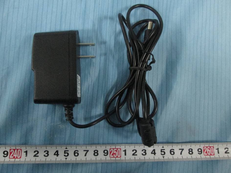
XTX-EZC
Feb 17, 2015Fixed Wireless Phone
Equipment Class
JBP - Part 15 Class B Computing Device Peripheral
XTX-100
Feb 21, 2013EZ CARE
Equipment Class
CYY - Communications Receiver used w/Pt 15 Transmitter
XTX-LF500
Mar 07, 2011GPS Watch Tracker
Equipment Class
PCB - PCS Licensed Transmitter