XU8TEW673GRU300Mbps Concurrent Dual Band Wireless N Gigabit Router
TRENDNET, Inc.
Click to zoom
Application Details
- Equipment Class
- DTS - Digital Transmission System
- Date of Grant
- Jan 27, 2010
- Application Purpose
- Original Equipment
- Date of Application
- Jan 27, 2010
- Equipment Note
- 300Mbps Concurrent Dual Band Wireless N Gigabit Router
- Frequency Range
- 5745.00000000 - 5825.00000000
- Company
- TRENDNET, Inc.
- Country
- United States
Documents & Files
Document Text
Text extracted from the exhibit documents filed with the FCC. Open a document above to read the original.
Users Manual
i ii Federal Communication Commission Interference Statement This equipment has been tested and found to comply with the limits for a Class B digital device, pursuant to Part 15 of the FCC Rules. These limits are designed to provide reasonable protection against harmful interference when the equipment is operated in a commercial environment. This equipment generates, uses and can radiate radio frequency energy and, if not installed and used in accordance with the instructions, may cause harmful interference to radio communications. Operation of this equipment in a residential area is likely to cause harmful interference in which case the user will be required to correct the interference at his own expense. If this equipment does cause harmful interference to radio or television reception, which can be determined by turning the equipment off and on, the user is encouraged to try to correct the interference by one of the following measures: - Reorient or relocate the receiving antenna. - Increase the separation between the equipment and receiver. - Connect the equipment into an outlet on a circuit different from that to which the receiver is connected. - Consult the dealer or an experienced radio/TV technician for help. FCC Caution: Any changes or modifications not expressly approved by the party responsible for compliance could void the user's authority to operate this equipment. For operation within 5.15 ~ 5.25GHz frequency range, it is restricted to indoor environment. This device complies with Part 15 of the FCC Rules. Operation is subject to the following two conditions: (1) This device may not cause harmful interference, and (2) this device must accept any interference received, including interference that may cause undesired operation. IMPORTANT NOTE: Radiation Exposure Statement: This equipment complies with FCC radiation exposure limits set forth for an uncontrolled environment. This equipment should be installed and operated with minimum distance 20cm between the radiator & your body. This transmitter must not be co-located or operating in conjunction with any other antenna or transmitter. The availability of some specific channels and/or operational frequency bands are country dependent and are firmware programmed at the factory to match the intended destination. The firmware setting is not accessible by the end user. iii Europe – EU Declaration of Conformity This device complies with the essential requirements of the R&TTE Directive 1999/5/EC. The following test methods have been applied in order to prove presumption of conformity with the essential requirements of the R&TTE Directive 1999/5/EC: EN60950-1: 2006 Safety of Information Technology Equipment EN 50385: 2002 Product standard to demonstrate the compliance of radio base stations and fixed terminal stations for wireless telecommunication systems with the basic restrictions or the reference levels related to human exposure to radio frequency electromagnetic fields (110MHz - 40 GHz) - General public EN 300 328 V1.7.1 (2006-10) Electromagnetic compatibility and Radio spectrum Matters (ERM); Wideband transmission systems; Data transmission equipment operating in the 2,4 GHz ISM band and using wide band modulation techniques; Harmonized EN covering essential requirements under article 3.2 of the R&TTE Directive EN 301 893 V1.4.1: (2007-07) Broadband Radio Access Networks (BRAN); 5 GHz high performance RLAN; Harmonized EN covering essential requirements of article 3.2 of the R&TTE Directive EN 301 489-1 V1.8.1 (2008-04) Electromagnetic compatibility and Radio Spectrum Matters (ERM); ElectroMagnetic Compatibility (EMC) standard for radio equipment and services; Part 1: Common technical requirements EN 301 489-17 V1.3.2 (2008-04) Electromagnetic compatibility and Radio spectrum Matters (ERM); ElectroMagnetic Compatibility (EMC) standard for radio equipment and services; Part 17: Specific conditions for 2,4 GHz wideband transmission systems and 5 GHz high performance RLAN equipment This device is a 2.4 GHz wideband transmission system (transceiver), intended for use in all EU member states and EFTA countries, except in France and Italy where restrictive use applies. In Italy the end-user should apply for a license at the national spectrum authorities in order to obtain authorization to use the device for setting up outdoor radio links and/or for supplying public access to telecommunications and/or network services. This device may not be used for setting up outdoor radio links in France and in some areas the RF output power may be limited to 10 mW EIRP in the frequency range of 2454 – 2483.5 MHz. For detailed information the end-user should contact the national spectrum authority in France. 0560 iv Česky [Czech] TRENDware tímto prohlašuje, že tento TEW-673GRU je ve shodě se základními požadavky a dalšími příslušnými ustanoveními směrnice 1999/5/ES. Dansk [Danish] Undertegnede TRENDware erklærer herved, at følgende udstyr TEW-673GRU overholder de væsentlige krav og øvrige relevante krav i direktiv 1999/5/EF. Deutsch [German] Hiermit erklärt TRENDware, dass sich das Gerät TEW-673GRU in Übereinstimmung mit den grundlegenden Anforderungen und den übrigen einschlägigen Bestimmungen der Richtlinie 1999/5/EG befindet. Eesti [Estonian] Käesolevaga kinnitab TRENDware seadme TEW-673GRU vastavust direktiivi 1999/5/EÜ põhinõuetele ja nimetatud direktiivist tulenevatele teistele asjakohastele sätetele. English Hereby, TRENDware declares that this TEW-673GRU is in compliance with the essential requirements and other relevant provisions of Directive 1999/5/EC. Español [Spanish] Por medio de la presente TRENDware declara que el TEW-673GRU cumple con los requisitos esenciales y cualesquiera otras disposiciones aplicables o exigibles de la Directiva 1999/5/CE. Ελληνική [Greek] ΜΕ ΤΗΝ ΠΑΡΟΥΣΑ TRENDware ∆ΗΛΩΝΕΙ ΟΤΙ TEW-673GRU ΣΥΜΜΟΡΦΩΝΕΤΑΙ ΠΡΟΣ ΤΙΣ ΟΥΣΙΩ∆ΕΙΣ ΑΠΑΙΤΗΣΕΙΣ ΚΑΙ ΤΙΣ ΛΟΙΠΕΣ ΣΧΕΤΙΚΕΣ ∆ΙΑΤΑΞΕΙΣ ΤΗΣ Ο∆ΗΓΙΑΣ 1999/5/ΕΚ. Français [French] Par la…
Text truncated - open the document above for the full version.
Users Manual
35 WIFI Protected Setup This screen enables users to configure the Wi-Fi Protected Setup function. WPS: Enable or Disable the WPS (Wi-Fi Protected Setup) function Status: Displays the state (Un-configured State/Configured State) information of WPS. Self-PIN Number: Display the default PIN number of the WLAN Router. Client PIN Number: Type Client PIN number that the client uses to negotiate with WLAN Router via WPS protocol. It is only used when users want their station to join WLAN Router's network. Push Button Configuration: Clicking this button will invoke the Push Button Configuration (PBC) method of WPS. It is only used when WLAN Router acts as a Registrar. This feature can also be used by pressing the WPS button on the side of the WLAN Router. 36 Status This selection enables users to view the status of the WLAN Router LAN, WAN and Wireless connections, and view logs and statistics pertaining to connections and packet transfers. Device Information This screen enables users to view the WLAN Router’s LAN, Wireless and WAN configurations. Firmware Version: Displays the latest build of the WLAN Router firmware interface. After updating the firmware in Tools - Firmware, check this to ensure that the firmware was successfully updated. WAN: This section displays the WAN interface configuration including the MAC address, Connection status, DHCP client status, IP address, Subnet mask, Default gateway, and DNS. Wireless 2.4G/5G: These sections displays the wireless configuration information, including the MAC address, the Connection status, SSID, Channel and Authentication type. LAN: This section displays the LAN interface configuration including the MAC address, IP Address, Subnet Mask, and DHCP Server Status. Click “DHCP Table” 37 to view a list of client stations currently connected to the WLAN Router LAN interface. Click “DHCP Release” to release all IP addresses assigned to client stations connected to the WAN via the WLAN Router. Click “DHCP Renew” to reassign IP addresses to client stations connected to the WAN. Log This screen enables users to view a running log of Router system statistics, events, and activities. The log displays up to 200 entries. Older entries are overwritten by new entries. The Log screen commands are as follows: Click “First Page” to view the first page of the log Click “Last Page” to view the final page of the log Click “Previous Page” to view the page just before the current page Click “Next Page” to view the page just after the current page Click “Clear Log” to delete the contents of the log and begin a new log Click “Refresh” to renew log statistics Time: Displays the time and date that the log entry was created. Message: Displays summary information about the log entry. 38 Log Setting This screen enables users to set Router Log parameters. SMTP Authentication: Select Enabled SMTP server authentication. SMTP Account: If the SMTP Authentication enabled, fill in the SMTP account name here. SMTP Password: If the SMTP Authentication enabled, fill in the password of the SMTP account here. SMTP Server: Type your SMTP server address here. Send to: Type an email address for the log to be sent to. Click “Email Log Now” to immediately send the current log. • E-mail Logs: When log is full - The time is not fixed. The log will be sent when the log is full, which will depend on the volume of traffic. • Every day, Every Monday ... - The log is sent on the interval specified. o If "Every day" is selected, the log is sent at the time specified. o If the day is specified, the log is sent once per week, on the specified day. o Select the time of day you wish the E-mail to be sent. o If the log is full before the time specified to send it, it will be sent regardless. Syslog Server: Type the IP address of the Syslog Server if user wants the WLAN Router to listen and receive incoming Syslog messages. 39 Log Type: Enables users to select what items will be included in the log: System Activity: Displays information related to WLAN Router operation. Debug Information: Displays information related to errors and system malfunctions. Attacks: Displays information about any malicious activity on the network. Dropped Packets: Displays information about packets that have not been transferred successfully. Notice: Displays important notices by the system administrator. Statistic This screen displays a table that shows the rate of packet transmission via the WLAN Router’s LAN, WAN ports and Wireless 2.4G/5G (in bytes per second). Click “Reset” to erase all statistics and begin logging statistics again. 40 Wireless This screen enables users to view wireless information about wireless devices that are connected to the WLAN Router. Connected Time: Lists all wireless clients and how long they have been connected WLAN Router. MAC Address: Displays the wireless client’s MAC address. Routing This selection enables users to set how the WLAN Router forwards data: Static and Dynamic. Routing Table enables users to view the information created by the WLAN Router that displays the network interconnection topology. Static It enables users to set parameters by which the WLAN Router forwards data to its destination if the network has a static IP address. Network Address: Type the static IP address the network uses to access the Internet. Contact the ISP or network administrator for this information. 41 Network Mask: Type the network (subnet) mask of the network. If this field is left blank, the network mask defaults to 255.255.255.0. Contact the ISP or network administrator for this information. Gateway Address: Type the gateway address of the network. Contact the ISP or network administrator for this information. Interface: Select an interface, WAN or LAN, to connect to the Internet. Metric: Select which metric that the user wants to apply to this configuration. Add: Click to add the configuration to the static IP address table at the bottom of the page. Update: Select one of the entries in the static IP…
Text truncated - open the document above for the full version.
Attestation Statements
20675 Manhattan Place, Torrance, CA 90501, USA TEL.: (310)961-5500 FAX: (310)961-5511 Date: 2010-01-07 General Declaration We, TRENDNET, Inc . declares that the device does not have “Ad Hoc on non-US frequencies” and/or “on DFS frequencies” while applying for the following product. Trademark: TRENDnet FCC ID: XU8TEW673GRU If you have any questions regarding the declaration, please don’t hesitate to contact us. Thank you! Sincerely yours, ------------------------------------------------- Wen Tsai /Sr. Product Manager TRENDNET, Inc. TEL.: (310)961-5500 ext.5474 FAX: (310)961-5511 [email protected]
Cover Letter(s)
2010-01-07 FCC ID: XU8TEW673GRU Federal Communications Commission Authorization and Evaluation Division Confidentiality Request Pursuant to Sections 0.457 and 0.459 of the Commission’s Rules, the Applicant hereby requests confidential treatment of information accompanying this Application as outlined below: Schematics Block Diagram The above materials contain trade secrets and proprietary information not customarily released to the public. The public disclosure of these matters might be harmful to the Applicant and provide unjustified benefits to its competitors. The Applicant understands that pursuant to Rule 0.457, disclosure of this Application and all accompanying documentation will not be made before the date of the Grant for this application. Sincerely, ___________________________________ Wen Tsai /Sr. Product Manager TRENDNET, Inc. TEL.: (310)961-5500 ext.5474 FAX: (310)961-5511 [email protected] 20675 Manhattan Place, Torrance, CA 90501, USA TEL.: (310)961-5500 FAX: (310)961-5511
Cover Letter(s)
20675 Manhattan Place, Torrance, CA 90501, USA TEL.: (310)961-5500 FAX: (310)961-5511 AUTHORIZATION LETTER 2010-01-07 To whom it may concern: We, the undersigned, TRENDNET, Inc. hereby authorize Bureau Veritas Consumer Products Services (H.K.) Ltd., Taoyuan Branch (BV CPS Taoyuan) of Taiwan to act on our behalf in all matters relating to all processes required FCC and any communication needed with the national authority. Any and all acts carried out by BV CPS Taoyuan on our behalf shall have the same effects as acts of our own. If you have any questions regarding the authorization, please don’t hesitate to contact us. Thank you! Sincerely yours, ------------------------------------------------------------------- Wen Tsai /Sr. Product Manager TRENDNET, Inc. TEL.: (310)961-5500 ext.5474 FAX: (310)961-5511 [email protected]
External Photos
Page 1 CONSTRUCTION PHOTOS OF EUT Page 2 Page 3
ID Label/Location Info
TRENDnet MADE IN CHINA 0560 This device complies with part 15 of the FCC Rules. Operation is subject to the following two conditions: (1)this device may not cause harmful interference and (2)this device must accept any interference received, including interference that may cause undesired operation. TEW-673GRU REV.Av FCC ID: Power Input: 12V 2A XU8TEW673GRU LAN MAC: XXXXXXXXXXXX WAN MAC: XXXXXXXXXXXX/#
ID Label/Location Info
FCC ID .: XU8TEW673GRU Label Location
Internal Photos
Page 4 Page 5 Page 6 Page 7 Page 8 Page 9 Page 10 Page 11 Page 12 Page 13
Operational Description
FCC ID: XU8TEW673GRU Report No.: RF981022L16A Reference No.: 990106L06 OPERATIONAL DESCRIPTION This device is a 300Mbps Concurrent Dual Band Wireless N Gigabit Router, which operates in both of the 5GHz and 2.4GHz bands and can transmitting simultaneously, the maximum data rate could be up to 300Mbps which OFDM technique. If the signal to noise radio is too poor which could not support 300Mbps, the 11Mbps data rate with DSSS technique will be applied. The transmitter of the EUT is powered by AC adapter. The antenna is Dipole antenna with R-SMA antenna connector. For more detailed instruction, please take a look at the user’s manual. FCC 15.407(c) states: The device shall automatically discontinue transmission in case of either absence of information to transmit or operational failure. These provisions are not intended to preclude the transmission of control or signaling information or the use of repetitive codes used by certain digital technologies to complete frame or burst intervals. Applicants shall include in their application for equipment authorization a description of how this requirement is met” Data transmission is always initiated by software, which is then pass down through the MAC, through the digital and analog baseband, and finally to the RF chip. Several special packets (ACKs, CTS, PSPoll, etc...) are initiated by the MAC. There are the only ways the digital baseband portion will turn on the RF transmitter, which it then turns off at the end of the packet. Therefore, the transmitter will be on only while one of the aforementioned packets are being transmitted.
RF Exposure Info
Report No.: SA981022L16A Report Format Version 3.0.1 Reference No.: 990106L06 1 RF EXPOSURE REPORT REPORT NO.: SA981022L16A MODEL NO.: TEW-673GRU FCC ID: XU8TEW673GRU ACCORDING: FCC Guidelines for Human Exposure IEEE C95.1 APPLICANT: TRENDNET, Inc. ADDRESS: 20675 Manhattan Place, Torrance, CA 90501, USA ISSUED BY: Bureau Veritas Consumer Products Services (H.K.) Ltd., Taoyuan Branch LAB ADDRESS: No. 47, 14th Ling, Chia Pau Tsuen, Lin Kou Hsiang, Taipei Hsien 244, Taiwan, R.O.C. TEST LOCATION: No. 19, Hwa Ya 2nd Rd, Wen Hwa Tsuen, Kwei Shan Hsiang, Taoyuan Hsien 333, Taiwan, R.O.C. Report No.: SA981022L16A Report Format Version 3.0.1 Reference No.: 990106L06 2 RF EXPOSURE MEASUREMENT (MOBILE DEVICE) 1. INTRODUCTION In this document, we try to prove the safety of radiation harmfulness to the human body for our product. The limit for Maximum Permissible Exposure (MPE) specified in FCC 1.1310 is followed. The Gain of the antenna used in this product is measured in a Fully Anechoic Chamber (FAC) calibrated for antenna measurement in ADT, and also the maximum total power input to the antenna is measured. Through the Friis transmission formula and the maximum gain of the antenna, we can calculate the distance, away from the product, where the limit of MPE is reached. Although the Friis transmission formula is a far field assumption, the calculated result of that is an over-prediction for near field power density. We will take that as the worst case to specify the safety range. 2. RF EXPOSURE LIMIT According to FCC 1.1310: The criteria listed in the following table shall be used to evaluate the environmental impact of human exposure to radio-frequency (RF) radiation as specified in 1.1307(b) LIMITS FOR MAXIMUM PERMISSIBLE EXPOSURE (MPE) FREQUENCY RANGE (MHz) ELECTRIC FIELD STRENGTH (V/m) MAGNETIC FIELD STRENGTH (A/m) POWER DENSITY (mW/cm 2 ) AVERAGE TIME (minutes) (A)LIMITS FOR OCCUPATIONAL / CONTROL EXPOSURES 300-1500 ... ... F/300 6 1500-100,000 ... ... 5 6 (B)LIMITS FOR GENERAL POPULATION / UNCONTROLLED EXPOSURE 300-1500 ... ... F/1500 30 1500-100,000 ... ... 1.0 30 F = Frequency in MHz Report No.: SA981022L16A Report Format Version 3.0.1 Reference No.: 990106L06 3 3. FRIIS FORMULA Friis transmission formula : Pd = (Pout*G) / (4*pi*r 2 ) where Pd = power density in mW/cm 2 Pout = output power to antenna in mW G = gain of antenna in linear scale Pi = 3.1416 R = distance between observation point and center of the radiator in cm If we know the maximum Gain of the antenna and the total power input to the antenna, through the calculation, we will know the MPE value at distance r. Ref.: David K. Cheng, Field and Wave Electromagnetics, Second Edition, Page 640, Eq. (11-133). 4. EUT OPERATING CONDITION The software provided by Manufacturer enabled the EUT to transmit and receive data at lowest, middle and highest channel individually. 5. CLASSIFICATION The antenna of this product, under normal use condition, is at least 20cm away from the body of the user. Warning statement to the user for keeping at least 20cm or more separation distance with the antenna should be included in users manual. So, this device is classified as Mobile Device. Report No.: SA981022L16A Report Format Version 3.0.1 Reference No.: 990106L06 4 6. TEST RESULTS 6.1 ANTENNA GAIN The maximum Gain measured in Fully Anechoic Chamber are 2dBi or 1.58 (numeric) (for 2.4GHz antenna); 3dBi or 2.00(numeric) (for 5.0GHz). 6.2 OUTPUT POWER INTO ANTENNA & RF EXPOSURE VALUE AT DISTANCE 20cm: For 2.412 ~ 2.462GHz band: POWER OUTPUT (dBm) CHAIN 0 CHAIN 1 TOTAL POWER (mW) TOTAL POWER (dBm) POWER DENSITY (mW/ cm 2 ) LIMIT OF POWER DENSITY (mW/ cm 2 ) 23.4 23.1 422.9 26.3 0.133 1.000 For 5.180 ~ 5.240GHz band: POWER OUTPUT (dBm) CHAIN 0 CHAIN 1 TOTAL POWER (mW) TOTAL POWER (dBm) POWER DENSITY (mW/ cm 2 ) LIMIT OF POWER DENSITY (mW/ cm 2 ) 11.5 12.3 31.1 14.9 0.012 1.000 For 5.745 ~ 5.825GHz band: POWER OUTPUT (dBm) CHAIN 0 CHAIN 1 TOTAL POWER (mW) TOTAL POWER (dBm) POWER DENSITY (mW/cm 2 ) LIMIT OF POWER DENSITY (mW/ cm 2 ) 23.0 22.6 381.5 25.8 0.151 1.000 CONCULSION: Both of the WLAN 2.4G & 5.0G can transmit simultaneously, the formula of calculated the MPE is: CPD1 / LPD1 + CPD2 / LPD2 + ......etc. < 1 CPD = Calculation power density LPD = Limit of power density 1. WLAN 2.4G + WLAN 5.0G = 0.284 Therefore, the maximum calculation of this situation is 0.284, which is less than the “1” limit.
Test Report
Report No.: RF981022L16A 1 Report Format Version 3.0.1 Reference No.: 990106L06 FCC TEST REPORT (15.247) REPORT NO.: RF981022L16A MODEL NO.: TEW-673GRU RECEIVED: Sep. 08, 2009 TESTED: Oct. 29 ~ Nov. 21, 2009 ISSUED: Jan. 19, 2010 APPLICANT: TRENDNET, Inc. ADDRESS: 20675 Manhattan Place, Torrance, CA 90501, USA ISSUED BY: Bureau Veritas Consumer Products Services (H.K.) Ltd., Taoyuan Branch LAB ADDRESS: No. 47, 14th Ling, Chia Pau Tsuen, Lin Kou Hsiang, Taipei Hsien 244, Taiwan, R.O.C. TEST LOCATION: No. 19, Hwa Ya 2nd Rd, Wen Hwa Tsuen, Kwei Shan Hsiang, Taoyuan Hsien 333, Taiwan, R.O.C. This test report consists of 116 pages in total. It may be duplicated completely for legal use with the approval of the applicant. It should not be reproduced except in full, without the written approval of our laboratory. The client should not use it to claim product endorsement by TAF or any government agencies. The test results in the report only apply to the tested sample. Report No.: RF981022L16A 2 Report Format Version 3.0.1 Reference No.: 990106L06 TABLE OF CONTENTS 1. CERTIFICATION........................................................................................................... 5 2. SUMMARY OF TEST RESULTS .................................................................................. 6 2.1 MEASUREMENT UNCERTAINTY ............................................................................... 6 3. GENERAL INFORMATION ........................................................................................... 7 3.1 GENERAL DESCRIPTION OF EUT ............................................................................. 7 3.2 DESCRIPTION OF TEST MODES ............................................................................... 9 3.2.1 CONFIGURATION OF SYSTEM UNDER TEST ........................................................ 10 3.2.2 TEST MODE APPLICABILITY AND TESTED CHANNEL DETAIL ............................. 11 3.3 GENERAL DESCRIPTION OF APPLIED STANDARDS ............................................ 15 3.4 DESCRIPTION OF SUPPORT UNITS ....................................................................... 15 4. TEST TYPES AND RESULTS (FOR 2.4GHz BAND)................................................. 16 4.1 RADIATED EMISSION MEASUREMENT .................................................................. 16 4.1.1 LIMITS OF RADIATED EMISSION MEASUREMENT................................................ 16 4.1.2 TEST INSTRUMENTS................................................................................................ 17 4.1.3 TEST PROCEDURES ................................................................................................ 18 4.1.4 DEVIATION FROM TEST STANDARD....................................................................... 18 4.1.5 TEST SETUP.............................................................................................................. 19 4.1.6 EUT OPERATING CONDITIONS ............................................................................... 19 4.1.7 TEST RESULTS ......................................................................................................... 20 4.2 CONDUCTED EMISSION MEASUREMENT ............................................................. 33 4.2.1 LIMITS OF CONDUCTED EMISSION MEASUREMENT........................................... 33 4.2.2 TEST INSTRUMENTS................................................................................................ 33 4.2.3 TEST PROCEDURES ................................................................................................ 34 4.2.4 DEVIATION FROM TEST STANDARD....................................................................... 34 4.2.5 TEST SETUP.............................................................................................................. 35 4.2.6 EUT OPERATING CONDITIONS ............................................................................... 35 4.2.7 TEST RESULTS ......................................................................................................... 36 4.3 6dB BANDWIDTH MEASUREMENT.......................................................................... 38 4.3.1 LIMITS OF 6dB BANDWIDTH MEASUREMENT ....................................................... 38 4.3.2 TEST INSTRUMENTS................................................................................................ 38 4.3.3 TEST PROCEDURE................................................................................................... 38 4.3.4 DEVIATION FROM TEST STANDARD....................................................................... 38 4.3.5 TEST SETUP.............................................................................................................. 39 4.3.6 EUT OPERATING CONDITIONS ............................................................................... 39 4.3.7 TEST RESULTS ......................................................................................................... 40 4.4 MAXIMUM OUTPUT POWER .................................................................................... 44 4.4.1 LIMITS OF MAXIMUM OUTPUT POWER MEASUREMENT..................................... 44 4.4.2 INSTRUMENTS .......................................................................................................... 44 4.4.3 TEST PROCEDURE................................................................................................... 44 4.4.4 DEVIATION FROM TEST STANDARD....................................................................... 45 4.4.5 TEST SETUP.............................................................................................................. 45 4.4.6 EUT OPERATING CONDITIONS ............................................................................... 45 4.4.7 TEST RESULTS ......................................................................................................... 46 4.5 POWER SPECTRAL DENSITY MEASUREMENT .…
Text truncated - open the document above for the full version.
Test Report
Report No.: RF981022L16A-1 1 Report Format Version 3.0.1 Reference No.: 990106L06 FCC TEST REPORT (15.407) REPORT NO.: RF981022L16A-1 MODEL NO.: TEW-673GRU RECEIVED: Sep. 08, 2009 TESTED: Sep. 08 ~ Nov. 21, 2009 ISSUED: Jan. 19, 2010 APPLICANT: TRENDNET, Inc. ADDRESS: 20675 Manhattan Place, Torrance, CA 90501, USA ISSUED BY: Bureau Veritas Consumer Products Services (H.K.) Ltd., Taoyuan Branch LAB ADDRESS: No. 47, 14th Ling, Chia Pau Tsuen, Lin Kou Hsiang, Taipei Hsien 244, Taiwan, R.O.C. TEST LOCATION: No. 19, Hwa Ya 2nd Rd, Wen Hwa Tsuen, Kwei Shan Hsiang, Taoyuan Hsien 333, Taiwan, R.O.C. This test report consists of 69 pages in total. It may be duplicated completely for legal use with the approval of the applicant. It should not be reproduced except in full, without the written approval of our laboratory. The client should not use it to claim product endorsement by TAF or any government agencies. The test results in the report only apply to the tested sample. Report No.: RF981022L16A-1 2 Report Format Version 3.0.1 Reference No.: 990106L06 TABLE OF CONTENTS 1. CERTIFICATION........................................................................................................... 4 2. SUMMARY OF TEST RESULTS .................................................................................. 5 2.1 MEASUREMENT UNCERTAINTY................................................................................ 5 3. GENERAL INFORMATION ........................................................................................... 6 3.1 GENERAL DESCRIPTION OF EUT ............................................................................. 6 3.2 DESCRIPTION OF TEST MODES ............................................................................... 8 3.2.1 CONFIGURATION OF SYSTEM UNDER TEST .......................................................... 9 3.2.2 TEST MODE APPLICABILITY AND TESTED CHANNEL DETAIL ............................. 10 3.3 GENERAL DESCRIPTION OF APPLIED STANDARDS ............................................ 12 3.4 DESCRIPTION OF SUPPORT UNITS ....................................................................... 12 4. TEST TYPES AND RESULTS .................................................................................... 13 4.1 RADIATED EMISSION MEASUREMENT .................................................................. 13 4.1.1 LIMITS OF RADIATED EMISSION MEASUREMENT................................................ 13 4.1.2 LIMITS OF UNWANTED EMISSION OUT OF THE RESTRICTED BANDS .............. 13 4.1.3 TEST INSTRUMENTS................................................................................................ 13 4.1.4 TEST PROCEDURES ................................................................................................ 15 4.1.5 DEVIATION FROM TEST STANDARD....................................................................... 15 4.1.6 TEST SETUP...........................................................…
Text truncated - open the document above for the full version.
Contact Information
Applicant
Wen Tsai(Sr. Product Manager)
Technical Contact
Bureau Veritas CPS (H.K.) Ltd. Taoyuan BranchGary Chang
[email protected]886-3-3183232
No. 19, Hwa Ya 2nd Rd., Kwei Shan Hsiang · Taoyuan Hsien · Taiwan
Non-Technical Contact
Bureau Veritas CPS (H.K.) Ltd. Taoyuan BranchEllis Wu
[email protected]886-3-3183232
Test Firm
Bureau Veritas CPS (H.K.) Ltd. Taoyuan BranchRichard Chen
Technical Specifications
| # | Rule Parts | Frequency Range | Power Output |
|---|---|---|---|
| 2 | 15C | 5.75 GHz - 5.83 GHz | 382.00 mW |
Other Applications from TRENDNET, Inc.
XU8TEW921DAP
Apr 29, 2021AX1800 Dual Band WiFi 6 PoE+ Access Point
Equipment Class
DTS - Digital Transmission System
XU8TEW831DR
Jul 19, 2020AC1200 Wireless Dual band Gigabit Router
Equipment Class
NII - Unlicensed National Information Infrastructure TX
XU8TEW740APBOV3
Apr 15, 202010 dBi Wireless N300 Outdoor PoE Access Point, 10 dBi Wireless N300 Outdoor PoE Preconfigured Point-to-Point Bridge Kit
Equipment Class
DTS - Digital Transmission System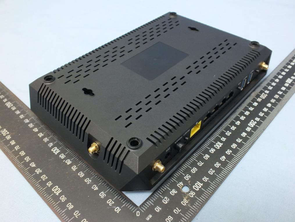
XU8TEW827DRU
Nov 25, 2015AC2600 StreamBoost TM MU-MIMO WiFi Router
Equipment Class
NII - Unlicensed National Information Infrastructure TX
XU8TVIP322WI
Oct 21, 2015IR Network Camera
Equipment Class
DTS - Digital Transmission System