XV6PST2200Occupancy Sensor
Telkonet, Inc.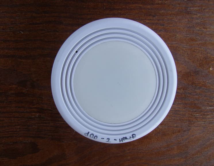
Click to zoom
Application Details
- Equipment Class
- DXX - Part 15 Low Power Communication Device Transmitter
- Date of Grant
- Jun 02, 2010
- Application Purpose
- Original Equipment
- Date of Application
- Jun 02, 2010
- Equipment Note
- Occupancy Sensor
- Frequency Range
- 917.48000000 - 917.48000000
- Company
- Telkonet, Inc.
- Country
- United States
Documents & Files
Document Text
Text extracted from the exhibit documents filed with the FCC. Open a document above to read the original.
Users Manual
Telkonet SmartEnergy 10200 Innovation Drive Milwaukee, WI 53226 Tel: (240) 912 -1800 Fax: (414) 258 - 8307 www.telkonet.com SS5200 Thermostat Installation & Maintenance Guidebook Document - 6.30.115 In This Training Guide 1. What is a SmartSystem? 2. How Does it Work? 3. Answering Common Guest Questions 4. Installing a New Sensor 5. Installing a New Thermostat 6. Linking the Sensor to the Thermostat 7. Troubleshooting 8. Product Returns What is a “SmartSystem”? Guest exits room and leaves thermostat set, for example, to 72 o . 1 2 3 4 5 6 7 8 9 10 11 12 Thermostat turns down while the room is empty to save energy, temperature drifts off of the set point. 1 2 3 4 5 6 7 8 9 10 11 12 Guest returns to room, air conditioner turns on to return the room temperature to guest’s setting. 1 2 3 4 5 6 7 8 9 10 11 12 Thermostat returns the room to the guest’s setting within about 15 minutes. 1 2 3 4 5 6 7 8 9 10 11 12 How Does it Work? Two units working together: People sensor on the ceiling Thermostat on the wall What Happens While a Guest is in the Room? Guest has full control of the thermostat while in the room. SmartSystems save energy in empty rooms. How Does the Sensor Know When the Room is Empty? Sensor detects motion and body heat. The sensor transmits the room status wirelessly. If You Walk Into a Room That Feels Too Warm or Too Cool... Room temperature will automatically return to the thermostat’s last setting within about 15 minutes. 1 2 3 4 5 6 7 8 9 10 11 12 1 2 3 4 5 6 7 8 9 10 11 12 Buttons on the Thermostat F AN H EAT C OOL A UTO O FF Turn continuous fan on/off. (This does not make it warmer or cooler, it just moves the air around.) Turn Heat or Cool on, or turn the system completely off. These are the “Warmer/Cooler” Buttons. Press these to raise or lower the temperature. Press Up Arrow for warmer, Down Arrow for cooler. Pictures on the Thermostat F AN H EAT C OOL A UTO O FF Temperature setting. Continuous fan is on (blank when fan is off). Flame = Heat mode on Snowflake = Cool mode on Blank = System is off Flashing flame or snowflake means the system is blowing warm or cool air at that moment. Batteries on sensor are low or missing, or sensor is gone. Sometimes this also means the sensor is broken. Note to Housekeeping and Front Desk • If products in the room are missing or have been vandalized... • If the thermostat screen is displaying a flashing wrench... • If the thermostat cover is not locked down... Note the room number and description of the problem and report it to maintenance right away. Answering Common Guest Questions When Housekeeping Finds a Problem in a Room • If products in the room are found to be vandalized or they are not functioning properly, note the room number and report it to maintenance right away. Too Hot or Too Cold If a guest returns to their room and complains it is too hot or too cold, “Please give it about fifteen minutes to return to your temperature setting.” Temperature Won’t Go Lower/Higher If the guest complains that the thermostat won’t let them set it as high or as low as they want. Explain to them that the thermostat has heat/cool limits, this prevents energy waste. NOTE: Setting the temperature to extreme temperatures will not make the room get warmer/cooler faster ! Thermostat is Clicking “Thermostat is making loud “clicking” noises. Have maintenance staff replace the thermostat right away. Thermostat Won’t Respond If the guest complains that they are setting the temperature on the thermostat but the system won’t turn on... The system has probably been turned off; ask the guest to press the HEAT/COOL button. Pressing this button will turn the system back on. A snowflake or flame symbol should always be displayed. If no symbol is displayed, the system has been turned off. What Happens While a Guest is in the Room? • When a guest is in the room, they control the room temperature, just like a regular thermostat. • A SmartSystem saves energy in an empty room. Installing a New Sensor Sensor Installation Steps - Overview Remove failed or vandalized sensor. Insert Batteries Connect new sensor to the base. Link the new sensor to the thermostat. 1. 2. 3. 4. Important Note About Installing a New Sensor • Units are linked using a wireless signal. • Never move a sensor to another room. – It will not work in the new room until you establish a new communication link between the new sensor and the thermostat. – Procedures for this are in the LINK THE SENSOR TO THE THERMOSTAT section. Remove the Failed or Vandalized Sensor • Remove the main body of the Sensor from the ceiling mounted base by turning it counter- clockwise. Insert Batteries • Make sure batteries align according to the images in the casing. The “curved” metal pieces of the battery clips should be touching the “flat” end of the batteries as shown below. Connect New Sensor to the Base • Re-attach the main body of the Sensor to the ceiling mounted base by aligning the slots with the tabs. Hold base plate in place and turn clockwise until it snaps into place. If it doesn’t line up, spin the sensor ¼ turn and try again. Be sure the security screw is aligned on both sides. After the Sensor is Installed • After you install the sensor you must link the sensor to the thermostat. Proceed to LINK THE SENSOR TO THE THERMOSTAT section. Installing a New Thermostat Thermostat Installation Steps - Overview Unlock thermostat Remove failed or vandalized thermostat Attach new thermostat to base plate Link sensor to thermostat. Lock buttons Lock down thermostat cover 1. 2. 3. 4. 5. 6. Important Note About Installing a New Thermostat • Units are linked using a wireless signal. • Never move a sensor to another room. – It will not work in the new room until you establish a new communication link between the new sensor and the thermostat. – Procedures for this are in the LINK THE SENSOR TO THE THERMOSTAT section. Unlock the Thermostat • Unlock the thermostat cover by removing the screw with the appropriate tool. Screw…
Text truncated - open the document above for the full version.
Users Manual
6.70.104 SS2000 / SS2200 Association Procedures 5/2010 Confidential – Information contained in this document is considered proprietary and confidential, and is intended for the internal use of Telkonet, Inc. our contracted Partners and VARs, and customers. This content is protected by all applicable copyright restrictions. © 2010 Telkonet, Inc. 1 Technical Note 6.70.104 SS2000 / SS2200 Association Procedures Scope: This document provides the process by which a SS2000 / SS2200 Occupancy Sensor is Associated to an SS1107 PTAC Controller or SS5000 / SS5200 Thermostat NOTE: This document applies only to the SS1107 PTAC Controller variant and SS5000 / SS5200 rev 4.5 and 5.1 Thermostat Models. Authors: Teejay Riedl, Robert Zirpoli Revision History: Revision Number Date Changed By: Summary of Change 1 12/2282008 Teejay Riedl / Robert Zirpoli Initial Draft 2 03/09/09 Teejay Riedl Audit Cycle 3 03/30/09 Teejay Riedl Merged data for SS5K association 4 06/16/09 Teejay Riedl Update 5 10/2009 Teejay Riedl Update; new numbering 6 5/27/2010 Robert Zirpoli Edited to include SS2200 Contents Overview...................................................................................................... 2 Terminology:............................................................................................. 2 Preparation:.................................................................................................. 2 Procedures: SS2000 to SS1107 Controller......................................................... 2 Step One – Power the Controller................................................................... 2 Step Two – Initiate the Association................................................................ 2 Procedures: SS2000 to 5000 Thermostat........................................................... 4 Step One – Power the Thermostat................................................................. 4 Step Two – Initiate the Association................................................................ 5 Step Three – Confirm the Association............................................................ 6 6.70.104 SS2000 / SS2200 Association Procedures 5/2010 Confidential – Information contained in this document is considered proprietary and confidential, and is intended for the internal use of Telkonet, Inc. our contracted Partners and VARs, and customers. This content is protected by all applicable copyright restrictions. © 2010 Telkonet, Inc. 2 Overview This document describes the process to associate (i.e. link) an SS2000 / SS2200 to either an SS1107 or SS5000 / SS5200. The document is separated by base-station type (SS1107 and SS5000 / SS5200). Terminology: • “Controller” – The SS1107 PTAC Controller unit • “Sensor” – The SS2000 / SS2200 Occupancy Sensor • “Poke” – the process of inserting the Smart Tool into the pinhole on a specified unit, and depressing the microswitch within for a period of approximately ¼ second (unless another hold time is specified). • “Smart Tool” – An unfolded paper clip or similar long, rigid wire Preparation: Ensure the components are installed per Telkonet Recommended Best Practices. In particular: • Controller should be solidly-affixed to the wall and/or outlet • Controller antenna should be extended, and not bunched-up inside the unit housing or wall • Sensor should be temporarily located in its desired location via double-sided tape (if radio link to the Controller) • Sensor should be firmly mounted to its desired location with all low-voltage wiring in place (if using hard-wired link and power from the Controller) Procedures: SS2000 to SS1107 Controller Step One – Power the Controller 1. Apply Power to the unit 2. Poke the Controller 3. The LED in the unit will begin a double flash (blink-blink-pause). This indicates that the Controller is in sensor acquisition mode. Observe the rate of the blinking (for comparison in step two) Step Two – Initiate the Association 1. Poke the sensor 2. Observe the LED on the controller. The LED should continue a double-blink, but the speed of the blink will double as well. 6.70.104 SS2000 / SS2200 Association Procedures 5/2010 3. After approximately 30 seconds, the LED will indicate the relative signal strength as red, yellow, or green. Yellow or Green are acceptable levels. If a red signal is shown, relocate the sensor to a better location. 4. Poke the 1107. The sensor LED will now blink to indicate the number of sensors which are associated to it. This blinking is normal, and allows an easy way for maintenance personnel to verify that the sensor(s) are still communicating to the controller. Figure 1: SS1107 ports, indicators, and controls Sensor Dissociation, SS1107 To force the SS1107 to drop sensor associations, follow these steps: 1. Press and hold the SS1107 microswitch for approximately 10 seconds. 2. The LED will double-blink red for 8-10 seconds while the switch is pressed, then go blank. 3. Once the LED is dark, all previously sensor associations will be deleted. Note that you cannot dissociate a single sensor from among multiples – all sensor association is dropped when the above process is invoked. You will need to re-associate any desired sensors. Confidential – Information contained in this document is considered proprietary and confidential, and is intended for the internal use of Telkonet, Inc. our contracted Partners and VARs, and customers. This content is protected by all applicable copyright restrictions. © 2010 Telkonet, Inc. 3 6.70.104 SS2000 / SS2200 Association Procedures 5/2010 Procedures: SS2000 / SS2200 to SS5000 / SS5200 Thermostat Unlocking the Command Mode NOTE: In some cases, depending on the installation and previous deployment, the SS5000 / SS5200 may have its command buttons “locked” to prevent tampering. If the procedures in “Step One” below do not allow control of the thermostat, follow these steps to unlock the Command functions 1 . 1. Press and hold the Fan button for ~7-10 seconds. 2. The display…
Text truncated - open the document above for the full version.
Users Manual
For more information, please email us at: [email protected]. Telkonet Communications, Inc. 20374 Seneca Meadows Parkway Germantown, Maryland 20876 Telephone: 877-282-2519 www.telkonet.com Copyright © 2009 Telkonet Inc. All rights Reserved. Document Number: 6.70.119 r4 Warning: Read all instructions carefully before installing this product. Battery Replacement Procedures for Telkonet SS2200-Series Occupancy Sensors SS2200 Occupancy Sensor for Telkonet Energy Management Systems Specifications: •Maximum Diameter (at face) - 13.0mm •Minimum Diameter (at base) - 11.3mm •Depth – 4cm •Weight (batteries loaded) – 1lb 1oz •Power Source – 4xAA Industrial Alkaline AA Alkaline batteries are the minimum permissible battery standard for SS2200 sensors. Non-alkaline “long-life” batteries will not yield acceptable long-term performance. Where possible, the use of “Industrial” batteries (Energizer EN-91-LR6-AM3 [Zn/MnO 2 ] or equivalent) is recommended. Batteries should be replaced as part of scheduled servicing as follows: • Standard Alkaline Batteries – Approximately every 24 months • Industrial / "Heavy Duty"Batteries – Approximately every 18 months Operational Notes: Following Sensor battery replacement, it is not necessary to perform the re-association process. The SS5000 / SS5200 Thermostat or SS1107 Controller will have already stored the Sensor’s unique ID. •For installation and support information, see Technical Note 6.30.115. •For information regarding associating SS2200- Series sensors see Technical Note 6.70.104 This equipment has been tested and found to comply with the limits for a class B digital device, pursuant to part 15 of the FCC Rules. These limits are designed to provide reasonable protection against harmful interference in a residential installation. This equipment generates, uses and can radiate radio frequency energy and if not installed and used in accordance with the instructions, may cause harmful interference to radio communications. However, there is no guarantee that interference will not occur in a particular installation. If this equipment does cause harmful interference to radio or television reception, which can be determined by turning the equipment off and on, the user is encouraged to try to correct the interference by one or more of the following measures: · Reorient or relocate the receiving antenna. · Increase the separation between the equipment and receiver. · Connect the equipment into an outlet on a circuit different from that to which the receiver is connected. · Consult the dealer or an experienced radio/ TV technician for help. The user is cautioned that changes and modifications made to the equipment without the approval of manufacturer could void the user’s authority to operate this equipment. Battery Replacement Procedure Step 1: Remove the retaining screw, and rotate the Sensor faceplate until it disengages from the mounted base. Step 2: Place the sensor faceplate on a stable, flat surface. Proceed with a good grip on the assembly and take care not to disengage the battery wires. With the batteries removed, take a moment to orient yourself with the battery clips and polarity markings on the unit. Note that: •The negative terminal clip for each battery is designed to act as a “spring” to push the battery’s positive terminal into place. •There is a small embossed polarity guide on the inside of the faceplate, just in front of the battery clips. Note the orientation when looking at the batteries from the side: •The bottom battery always has its positive terminal facing right •The top battery always has its positive terminal facing left •Check to ensure there is no oxidation or battery “acid” on the battery terminals. Dispose of used batteries in a safe and approved manner. Step 4: Insert the replacement batteries. Begin by placing the bottom battery, and then the top for each side. Whenever inserting batteries, it is best to place the negative battery end on the negative terminal, and then gently press the battery into the clip until it seats against the terminal. Ensure that there is nothing in between the battery terminals and the battery clips, such as stray insulation, paint chips, etc. The battery terminals must make firm, conducting contact with the battery clips. When placing the top batteries into the clips, take care not to press down on the spring negative clip. Excessive force will cause the metal terminal to slide down on the plastic bracket, and short against the bottom terminal. This will short- circuit the battery, resulting in possible damage the Sensor. Step 5: Visually double-check the assembly with the new batteries in place. Verify that: •Battery orientation is correct •Metal battery clips are not shorted against each other •The black power connector is firmly- attached to the circuit board •Touch the battery sides with your finger. If they are warm or hot to the touch, this is a clear indication of a shorted terminal. Re- examine the unit. Step 6: Verify that the retaining screw hole in the side of the Sensor assembly is oriented near the matching hole on the mounting plate. Insert the Sensor assembly into the mounting plate, and fix in place by rotating the unit slightly clockwise. Replace the retaining screw. Step 3: Remove the batteries. The battery clips are designed to hold the batteries snugly in place despite a wide variety of mounting options, so a small, flat-head screwdriver is often of use in removing the batteries. Figure 1 - Removing the Sensor from the Mounting Plate Figure 2 - Sensor Assembly on secure, flat surface Figure 3 - Battery Orientarion and clips Figure 4 - Inserting Batteries Figure 5 - Shorted clips
Cover Letter(s)
20374 Seneca Meadows Pkwy. ,!.Telkonet Germantown, MD 20876-7004 Phone: 2 40. 912.1800 Fax: 240.912.1839 • July 1, 2009 Compatible Electronics TCB 114 Olinda Drive Brea, California 92823 Subject: Request for withholding from public disclosme the schematic diagrams, block diagrams, and operational description pursuant to an application for certification, Gentlemen: We Telkonet, Inc., would like to request that all schematics, block diagrams, and operational descriptions submitted with our application for certification be withheld from public disclosure . per Section 0.459 of the FCC rules. . This request is made under the provisions of Section 0.457 (d) of the Commissions rules, and Section 552 (b)( 4) of the Freedom of Information Act. These sections authorize the withholding from public inspection, those materials which would be privileged as a matter of law if retained by the person submitting them, and materials which would not customarily be released to the public by that person. If you have any questions or need any additional information, please give me a call at 414-302-2208. 5m b (/) Matthew Koch Vice President, Hospitality Operations Telkonet, Inc.
Cover Letter(s)
1 Scott McCutchan From: Scott McCutchan [[email protected]] Sent: Thursday, April 22, 2010 3:39 PM To: '[email protected]' Cc: '[email protected]'; '[email protected]' Subject: FCC ID: XV6PST2200 Mr. Fujimoto: In order for processing of this certification application (FCC ID: XV6PST2200) to continue, the following issue(s) will have to be addressed: 1) It is indicated on the application form that confidentiality is requested, which must be accompanied by a confidentiality request letter from the applicant. Please submit this letter. 2) Please submit a complete user’s manual. The document submitted as the user’s manual is the battery replacement procedure. 3) According to the battery replacement procedure, this device can be externally powered by a SS 5000 / SS 5200 series thermostat. Was this mode of operation investigated? Also, if the thermostat connects to the AC mains (directly or indirectly), please provide conducted emissions data for this configuration. 4) According to the operational description and schematic diagrams, this device can optionally connect to a door switch. Were investigations made for this wiring configuration? 5) The schematics indicate two device models (R915H, R915V), each of which uses a different antenna (right angle, straight). Is this application intended cover both of these configurations? If so, were both antennas tested? The item(s) indicated above must be submitted before processing can continue on the above referenced application. Failure to provide the requested information within 60 days of the original e-mail date may result in application dismissal. and forfeiture of the filing fee. Also, please note that partial responses increase processin g time and should not be submitted. Please upload responses and/or exhibits to the electronic filing website. Your correspondence number is XV6PST2200-1. Best regards, Scott McCutchan Operations Manager Compatible Electronics TCB
Cover Letter(s)
1 Scott McCutchan From: Scott McCutchan [[email protected]] Sent: Monday, May 03, 2010 7:24 PM To: '[email protected]' Cc: '[email protected]'; '[email protected]' Subject: FCC ID: XV6PST2200 Mr. Fujimoto: In order for processing of this certification application (FCC ID: XV6PST2200) to continue, the following issue(s) will have to be addressed: 1) The user’s manual (battery replacement procedure) makes several references to technical notes for installation instructions and technical information. Since the manual does not address the installation and setup instructions, please submit the applicable technical notes. 2) If the device cannot be powered externally when in wireless mode, then the note in the manual about powering the device from a thermostat should either be removed, or be modified to make this indication to the user/installer. 3) The fact that the door switch option is not supported should be indicated in the operational description, and the user/installer should be instructed not to make this connection. 4) Please remove the reference to the un-tested right-angle antenna from the schematics. The item(s) indicated above must be submitted before processing can continue on the above referenced application. Failure to provide the requested information within 60 days of the original e-mail date may result in application dismissal. and forfeiture of the filing fee. Also, please note that partial responses increase processin g time and should not be submitted. Please upload responses and/or exhibits to the electronic filing website. Your correspondence number is XV6PST2200-2. Best regards, Scott McCutchan Operations Manager Compatible Electronics TCB
Cover Letter(s)
Correspondence by Project Project Number: 1258080053 Correspondence Number Memo XV6PST2200-1 1) It is indicated on the application form that confidentiality is requested, which must be accompanied by a confidentiality request letter from the applicant. Please submit this letter. Response: The Revised Confidentiality Letter has been uploaded. 2) Please submit a complete user’s manual. The document submitted as the user’s manual is the battery replacement procedure. Response: This is what will be the manual the end user see when they purchase the product, according to the client. They could write up something about changing the internal jumpers inside - which are not meant for the end user to change. 3) According to the battery replacement procedure, this device can be externally powered by a SS 5000 / SS 5200 series thermostat. Was this mode of operation investigated? Also, if the thermostat connects to the AC mains (directly or indirectly), please provide conducted emissions data for this confi guration. Response: The EUT can only be powered externally when the RF board is removed and the EUT is no longer a wireless device. The unit to be certified here is for the wireless device. 4) According to the operational description and schematic diagrams, this device can optionally connect to a door switch. Were investigations made for this wiring configuration? Response: The door switch option is not ready at this time. They would like the unit certified as is and will come back to test this option once it becomes available (software is not ready and no customer will be able to use this version at this time). 5) The schematics indicate two device models (R915H, R915V), each of which uses a different antenna (ri ght angle, straight). Is this application intended cover both of these configurations? If so, were both antennas tested? Response: The R915V was used (straight version). Per the client, they tested both internally for best range and then chose the best one (R915V) for the testing. So the R915V is the one (see internal photos) that will be certified.
Cover Letter(s)
Correspondence by Project Project Number: 1258080053 Correspondence Number Memo XV6PST2200-1 1) It is indicated on the application form that confidentiality is requested, which must be accompanied by a confidentiality request letter from the applicant. Please submit this letter. Response: The Revised Confidentiality Letter has been uploaded. 2) Please submit a complete user’s manual. The document submitted as the user’s manual is the battery replacement procedure. Response: This is what will be the manual the end user see when they purchase the product, according to the client. They could write up something about changing the internal jumpers inside - which are not meant for the end user to change. 3) According to the battery replacement procedure, this device can be externally powered by a SS 5000 / SS 5200 series thermostat. Was this mode of operation investigated? Also, if the thermostat connects to the AC mains (directly or indirectly), please provide conducted emissions data for this confi guration. Response: The EUT can only be powered externally when the RF board is removed and the EUT is no longer a wireless device. The unit to be certified here is for the wireless device. 4) According to the operational description and schematic diagrams, this device can optionally connect to a door switch. Were investigations made for this wiring configuration? Response: The door switch option is not ready at this time. They would like the unit certified as is and will come back to test this option once it becomes available (software is not ready and no customer will be able to use this version at this time). 5) The schematics indicate two device models (R915H, R915V), each of which uses a different antenna (ri ght angle, straight). Is this application intended cover both of these configurations? If so, were both antennas tested? Response: The R915V was used (straight version). Per the client, they tested both internally for best range and then chose the best one (R915V) for the testing. So the R915V is the one (see internal photos) that will be certified. Correspondence Number Memo XV6PST2200-2 1) The user’s manual (battery replacement procedure) makes several references to technical notes for installation instructions and technical information. Since the manual does not address the installation and setup instructions, please submit the applicable technical notes. Response: The Applicable Technical Notes Have been Uploaded. 2) If the device cannot be powered externally when in wireless mode, then the note in the manual about powering the device from a thermostat should either be removed, or be modified to make this indication to the user/installer. Response: The manual has been revised to remove the fact about powering the device from a thermostat. 3) The fact that the door switch option is not supported should be indicated in the operational description, and the user/installer should be instructed not to make this connection. Response: The door switch option has been removed from the operational description. The door switch option is not available to any customer because the software has not been implemented and will not be for quite a while. 4) Please remove the reference to the un- tested right-angle antenna from the schematics. Response: The schematics have been revised to remove this reference Correspondence Number Memo XV6PST2200-2 1) The user’s manual (battery replacement procedure) makes several references to technical notes for installation instructions and technical information. Since the manual does not address the installation and setup instructions, please submit the applicable technical notes. Response: The Applicable Technical Notes Have been Uploaded. 2) If the device cannot be powered externally when in wireless mode, then the note in the manual about powering the device from a thermostat should either be removed, or be modified to make this indication to the user/installer. Response: The manual has been revised to remove the fact about powering the device from a thermostat. 3) The fact that the door switch option is not supported should be indicated in the operational description, and the user/installer should be instructed not to make this connection. Response: The door switch option has been removed from the operational description. The door switch option is not available to
Test Report
Report Number: B90618D1 FCC Part 15 Subpart B and FCC Section 15.249 Test Report Occupancy Sensor Model: SS2200 Brea Division 114 Olinda Drive Brea, CA 92823 (714) 579-0500 Agoura Division 2337 Troutdale Drive Agoura, CA 91301 (818) 597-0600 Silverado Division 19121 El Toro Road Silverado, CA 92676 (949) 589-0700 Lake Forest Division 20621 Pascal Way Lake Forest, CA 92630 (949) 587-0400 Page 1 of 17 FCC PART 15, SUBPART B and C TEST REPORT for OCCUPANCY SENSOR MODEL: SS2200 Prepared for TELKONET, INC. 20374 SENECA MEADOWS PARKWAY GERMANTOWN, MARYLAND 20876-7004 Prepared by:_____________________ KYLE FUJIMOTO Approved by:____________________ MICHAEL CHRISTENSEN COMPATIBLE ELECTRONICS INC. 114 OLINDA DRIVE BREA, CALIFORNIA 92823 (714) 579-0500 DATE: NOVEMBER 11, 2009 REPORT APPENDICES TOTAL BODY A B C D E PAGES 17 2 2 2 10 7 40 This report shall not be reproduced except in full, without the written approval of Compatible Electronics. Report Number: B90618D1 FCC Part 15 Subpart B and FCC Section 15.249 Test Report …
Text truncated - open the document above for the full version.
Contact Information
Applicant
Jeff Sobieski(Chief Technical Officer (CTO))
Technical Contact
Compatible Electronics, Inc.Kyle Fujimoto
[email protected]714-579-0500
114 Olinda Drive · Brea, California · United States
Test Firm
Compatible Electronics, Inc.Michael Christensen
Technical Specifications
| # | Rule Parts | Frequency Range | Power Output |
|---|---|---|---|
| 1 | 15C | 917.48 MHz - 917.48 MHz | - |
Other Applications from Telkonet, Inc.

XV6AIDA
May 04, 2023Aida Thermostat and Aida Controller
Equipment Class
DTS - Digital Transmission System
XV6SS6560
Dec 16, 2015EcoTouch
Equipment Class
DXT - Part 15 Low Power Transceiver, Rx Verified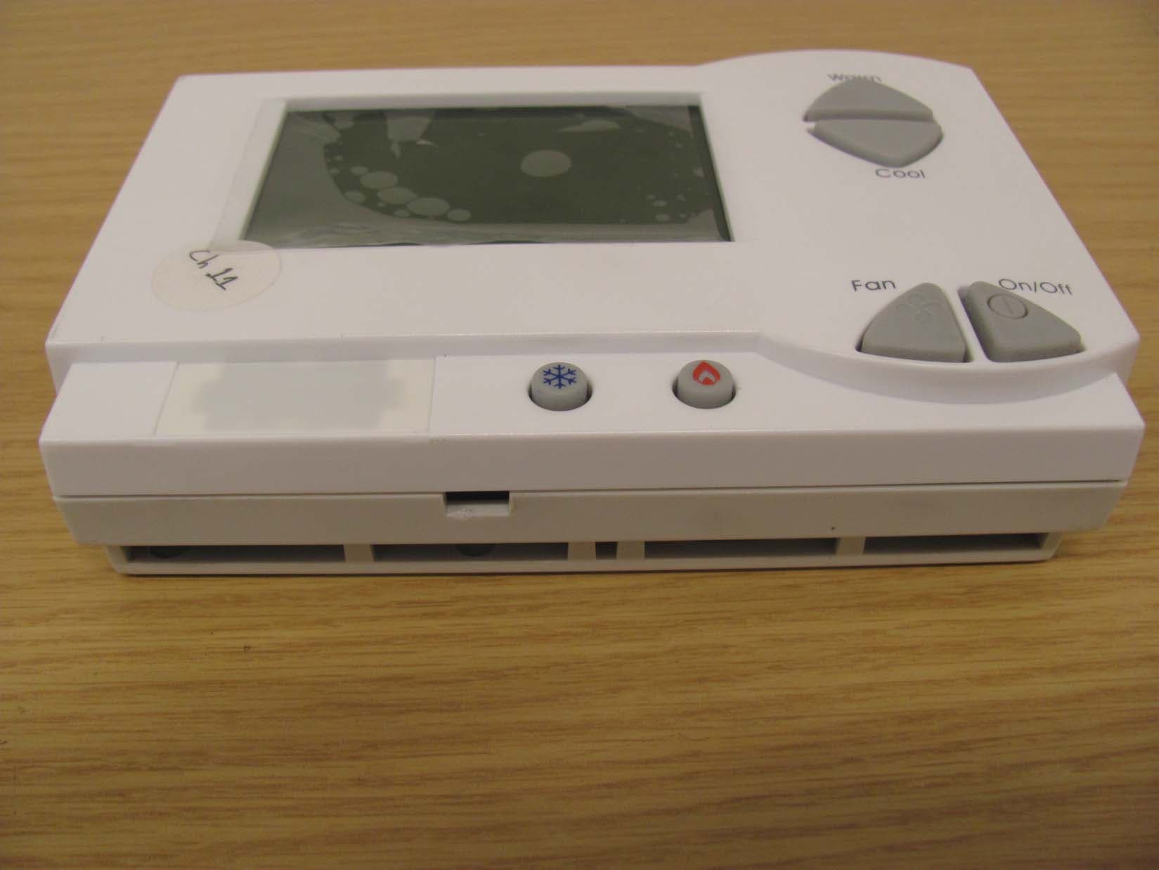
XV6PST6550
Sep 28, 2014EcoAir
Equipment Class
DXT - Part 15 Low Power Transceiver, Rx Verified
XV6PST62X0
Sep 28, 2014EcoView/EcoContact
Equipment Class
DXT - Part 15 Low Power Transceiver, Rx VerifiedXV6SS8030
Oct 27, 2013Load Control Module - Switch
Equipment Class
DXT - Part 15 Low Power Transceiver, Rx Verified