XVR-CONT8501Color Touchscreen Wi-Fi Thermostat
Trane US, Inc.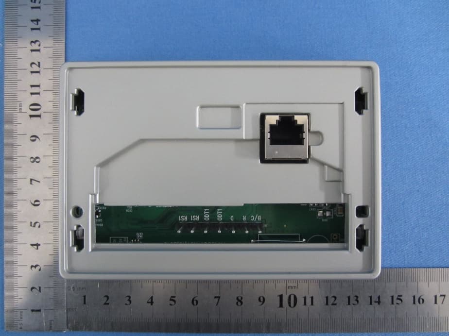
Click to zoom
Application Details
- Equipment Class
- DTS - Digital Transmission System
- Date of Grant
- Apr 01, 2014
- Application Purpose
- Original Equipment
- Date of Application
- Apr 01, 2014
- Equipment Note
- Color Touchscreen Wi-Fi Thermostat
- Frequency Range
- 2412.00000000 - 2462.00000000
- Company
- Trane US, Inc.
- Country
- United States
Documents & Files
Document Text
Text extracted from the exhibit documents filed with the FCC. Open a document above to read the original.
Users Manual
Trane XL850 Smart Control User Guide The XL850 is an easy-to-use, programmable control with a color touch-screen. When connected with Nexia™ Home Intelligence, you can control your home’s heating and cooling system and up to 230 separate Z-Wave devices from a smart phone, PC or tablet from virtually anywhere. This guide will help you configure and connect your XL850 Smart Control quickly and easily. 032-5091-01 Start using your new XL850 now! See “Start Here!” on page 3. page 2 XL850 User Guide Thank you for choosing the Trane XL850 Smart Control. The intuitive interface and powerful features incorporated into the compact design of the color touch-screen control represent the latest in climate control technology from the industry’s leader in residential HVAC systems. This guide will introduce you to the unit’s many features and get you started using your XL850 Smart Control right away. To enjoy the full benefit of your XL850 Smart Control, it should be connected to a Nexia™ Home Intelligence account. Nexia is a cloud- based platform that helps the smart products in your home work together through a single, convenient application. The XL850 can serve as the central hub of an entire network of home automation devices. Nexia™ Home Intelligence allows you to: • Monitor and control your HVAC system using an internet-enabled smart phone, tablet or computer from anywhere in the world. • Build a network of up to 230 Z-Wave enabled products on one account. • View weather information including outdoor temperature, five-day forecasts, radar and weather alerts. • Receive text and e-mail notifications that inform you of happenings in your home. • Receive software updates automatically. Congratulations! Start Here! ..................................................................3 Navigating the PlatinumXV Home Screen ............................................................4 Temperature Control Panel Screen ...................5 Menu Screen .............................................................6 Settings Screen ........................................................7 Scheduling Schedule Screen ......................................................8 Changing Periods ....................................................9 Adding Periods ......................................................10 Deleting Periods ....................................................11 Overriding Schedules ..........................................12 Configuring 1-Touch Presets .............................13 Nexia™ Home Intelligence Including/Excluding Z-Wave Devices ............15 Z-Wave Repeater Screen ....................................16 Security Settings Screen Lock Off ......................................................17 Screen Lock On ......................................................17 Guest Access ...........................................................17 Software Upgrades Automatic Upgrades ............................................18 Manual Upgrades ..................................................18 Notices FCC Notice ...............................................................19 ICC NOTICE ..............................................................19 Contents Up to four smart controls of any combination of the 950, 850, XL850 and 624 are allowed on your Nexia™ Home Intelligence account for no additional cost. A monthly subscription charge may apply beyond this number of devices. This product is compatible with Honeywell’s Enviracom® 2.0 protocol. Enviracom® is a registered trademark of Honeywell. 032-5091-01 page 3 The User Setup Wizard guides you through the XL850’s User configurable settings. To complete the Setup Wizard and connect the XL850 to Nexia™ Home Intelligence, you need: • An internet browser and high-speed connection to the Internet (wired or wireless) • Your wireless (WiFi) network name and password • A valid e-mail address To access the User Setup Wizard, press MeNU > SeTTINGS > USer SeTUP WIZard. When the Setup Wizard is activated, the process cannot be cancelled. The Wizard will guide you through the following steps: Screen Settings • Adjust the Screen brightness, backlight, screen saver and color themes. Schedule Settings • Set the XL850 scheduling feature to enabled or disabled. When Scheduling is disabled, 1-Touch Presets are available. Guided Scheduling (Scheduling enabled) • Automatically create schedules based on answers to a series of questions. 1-Touch Presets (Scheduling disabled) • Configure heating and cooling target temperatures for Home, Away and Sleep conditions. The Presets are selectable from the Home Screen. Network Setup Select your wireless network and enter your password. If your wireless network is available but not shown in the list, select Hidden Network, and manually enter your network’s name (SSID). NOTE: Wireless Setup is not required when the XL850 is hard-wired to your home network. Home networking troubleshooting tips can be found at www.nexiahome.com/trane. Nexia™ Home Intelligence registration (requires Internet connection) • Your XL850 Control comes equipped with remote access and other features from Nexia™ Home Intelligence. NOTE: If you are having difficulty enrolling the XL850 to your account, visit the troubleshooting section on www.nexiahome.com/trane for help. Weather (requires Nexia registration) • Input the Zip Code of the Location for appropriate weather information including five-day forecasts, radar display and weather alerts. That’s it! You can now begin enjoying the benefits of your new Trane XL850 Smart Control! Start Here! User Setup Wizard Menu Settings User Setup Wizard Accessing the User Setup Wizard page 4 XL850 User Guide Navigating the XL850 Home Screen 4:19 PM 37 ° 16 % Tue, Dec 16 System Idle Following Schedule Home Indoor Temp 76 ° Menu Auto System Mode Circulate Fan Mode Auto Air Cleaner $ Away 78° . . . 70° Outdoor Temp L 39° H 46° Indoor Humidity Status Noti cations and System Alerts appear here Date and Ti…
Text truncated - open the document above for the full version.
Cover Letter(s)
James Johnson
Cover Letter(s)
James Johnson
Cover Letter(s)
James Johnson
ID Label/Location Info
Label Location:
RF Exposure Info
FCC ID: XVR-CONT8501 RF Exposure Evaluation Limits The criteria listed in the following table shall be used to evaluate the environment impact of human exposure to radio frequency (RF) radiation as specified in 1.1307(b) Limits for Maximum Permissible Exposure (MPE) Frequency range (MHz) Electric field strength (V/m) Magnetic field strength (A/m) Power density (mW/cm 2 ) Averaging time (minutes) (A) Limits for Occupational/Controlled Exposures 0.3–3.0 614 1.63 *(100) 6 3.0–30 1842/f 4.89/f *(900/f 2 ) 6 30–300 61.4 0.163 1.0 6 300–1500 f/300 6 1500–100,000 5 6 (B) Limits for General Population/Uncontrolled Exposure 0.3–1.34 614 1.63 *(100) 30 1.34–30 824/f 2.19/f *(180/f 2 ) 30 30–300 27.5 0.073 0.2 30 300–1500 f/1500 30 1500–100,000 1.0 30 f = frequency in MHz Friis transmission formula: Pd = 30*Pout*G/377*d 2 Where Pd = power density in mW/cm 2 , Pout = output power to antenna in mW; G = gain of antenna in linear scale; d = distance between observation point and center of the radiator in cm Pd id the limit of MPE, 1 mW/cm 2 . If we know the maximum gain of the antenna and the total power input to the antenna, through the calculation, we will know the distance r where the MPE limit is reached. Test Procedure Software provided by client enabled the EUT to transmit and receive data at lowest, middle and highest channel individually. Test Result of RF Exposure Evaluation 802.11b mode Channel Output power to antenna (mW) Power Density at R=20cm (mW/cm 2 ) Limit (mW/cm 2 ) Result Lowest (2412MHz) 54.200 0.01078 1.0 PASS Middle (2437MHz) 41.976 0.00835 1.0 PASS Highest (2462MHz) 44.259 0.00880 1.0 PASS 802.11g mode Channel Output power to antenna (mW) Power Density at R=20cm (mW/cm 2 ) Limit (mW/cm 2 ) Result Lowest (2412MHz) 44.978 0.00895 1.0 PASS Middle (2437MHz) 40.644 0.00809 1.0 PASS Highest (2462MHz) 35.318 0.00703 1.0 PASS 802.11n(HT20) mode Channel Output power to antenna (mW) Power Density at R=20cm (mW/cm2) Limit (mW/cm 2 ) Result Lowest (2412MHz) 46.238 0.00920 1.0 PASS Middle (2437MHz) 41.879 0.00833 1.0 PASS Highest (2462MHz) 36.392 0.00724 1.0 PASS 802.11n(HT40) mode Channel Output power to antenna (mW) Power Density at R=20cm (mW/cm 2 ) Limit (mW/cm 2 ) Result Lowest (2422MHz) 52.966 0.01054 1.0 PASS Middle (2437MHz) 59.429 0.01182 1.0 PASS Highest (2452MHz) 52.119 0.01037 1.0 PASS Remark: antenna gain=0 dBi
Test Report
Global United Technology Services Co., Ltd. Report No.: GTSE13110184701 Authorized Signature: Robinson Lo Laboratory Manager This report details the results of the testing carried out on one sample. The results contained in this test report do not relate to other samples of the same product and does not permit the use of the GTS product certification mark. The manufacturer should ensure that all products in series production are in conformity with the product sample detailed in this report. This report may only be reproduced and distributed in full. If the product in this report is used in any configuration other than that detailed in the report, the manufacturer must ensure the new system complies with all relevant standards. Any mention of GTS or testing done by GTS in connection with, distribution or use of the product described in this report must be approved by GTS in writing. This document cannot be reproduced except in full, without prior written approval of the Company. Any unauthorized alteration, forgery or falsification of the content or appearance of this document is unlawful and offenders may be prosecuted to the fullest extent of the law. Unless otherwise stated the results shown in this test report refer only to the sample(s) tested and such sample(s) are retained for 90 days only. FCC REPORT Applicant: Trane US, Inc. Address of Applicant: 6200 Troup Highway Tyler TX 75707 Equipment Under Test (EUT) Product Name: Color Touchscreen Wi-Fi Thermostat Model No.: TCONT850AC52UAA, ACONT850AC52UAA FCC ID: XVR-CONT8501 Applicable standards: FCC CFR Title 47 Part 15 Subpart C Section 15.247:2013 Date of sample receipt: November 25, 2013 Date of Test: March 03-06, 2014 Date of report issued: March 06, 2014 Test Result : PASS * * In the configuration tested, the EUT complied with the standards specified above. Report No.: GTSE13110184701 Global United Technology Services Co., Ltd. Project No.: GTSE131101847RF 2nd Floor, Block No.2, Laodong Industrial Zone, Xixiang Road Baoan District, Shenzhen, China 518102 Telephone: +86 (0) 755 2779 8480 Fax: +86 (0) 755 2779 8960 Page 2 of 65 2 Version Version No. Date Description 00 March 06, 2014 Original Prepared By: Date: March 06, 2014 Project Engineer Check By: Date: March 06, 2014 Reviewer Report No.: GTSE13110184701 Global United Technology Services Co., Ltd. Project No.: GTSE131101847RF 2nd Floor, Block No.2, Laodong Industrial Zone, Xixiang Road Baoan District, Shenzhen, China 518102 Telephone: +86 (0) 755 2779 8480 Fax: +86 (0) 755 2779 8960 Page 3 of 65 3 Contents Page 1 COVER PAGE ........................................................................................................................................... 1 2 VERSION .................................................................................................................................................. 2 3 CONTENTS .............................................................................................................................................. 3 4 TEST SUMMARY ..................................................................................................................................... 4 5 GENERAL INFORMATION ...................................................................................................................... 5 5.1 CLIENT INFORMATION ......................................................................................................................... 5 5.2 GENERAL DESCRIPTION OF EUT ......................................................................................................... 5 5.3 TEST MODE ........................................................................................................................................ 6 5.4 DESCRIPTION OF SUPPORT UNITS ....................................................................................................... 6 5.5 TEST FACILITY .................................................................................................................................... 7 5.6 TEST LOCATION ................................................................................................................................. 7 6 TEST INSTRUMENTS LIST ..................................................................................................................... 8 7 TEST RESULTS AND MEASUREMENT DATA ...................................................................................... 9 7.1 ANTENNA REQUIREMENT: .................................................................................................................... 9 7.2 CONDUCTED EMISSIONS ................................................................................................................... 10 7.3 CONDUCTED PEAK OUTPUT POWER .................................................................................................. 13 7.4 CHANNEL BANDWIDTH ...................................................................................................................... 18 7.5 POWER SPECTRAL DENSITY ............................................................................................................. 23 7.6 BAND EDGES .................................................................................................................................... 28 7.6.1 Conducted Emission Method ..................................................................................................... 28 7.6.2 Radiated Emission Method ........................................................................................................ 31 7.7 SPURIOUS EMISSION ......................................................................................................................... 36 7.7.1 Conducted Emission Method ..................................................................................................... 36 7.7.2 Radiated Emission Method ........................................................................…
Text truncated - open the document above for the full version.
Test Setup Photos
Radiated Emission Conducted Emission
Contact Information
Applicant
Bradley Thomas Wilson(Embedded Controls Hardware Engineering Manager)
Test Firm
Global United Technology Service Co., LtdRobinson Lo
Technical Specifications
| # | Rule Parts | Frequency Range | Power Output |
|---|---|---|---|
| 1 | 15C | 2.41 GHz - 2.46 GHz | 59.43 mW |
Other Applications from Trane US, Inc.
XVREHMID1
Jul 03, 2026HVAC Performance Monitoring Kit
Equipment Class
DTS - Digital Transmission SystemXVREHMOD1
Jul 03, 2026HVAC Performance Monitoring Kit
Equipment Class
DTS - Digital Transmission System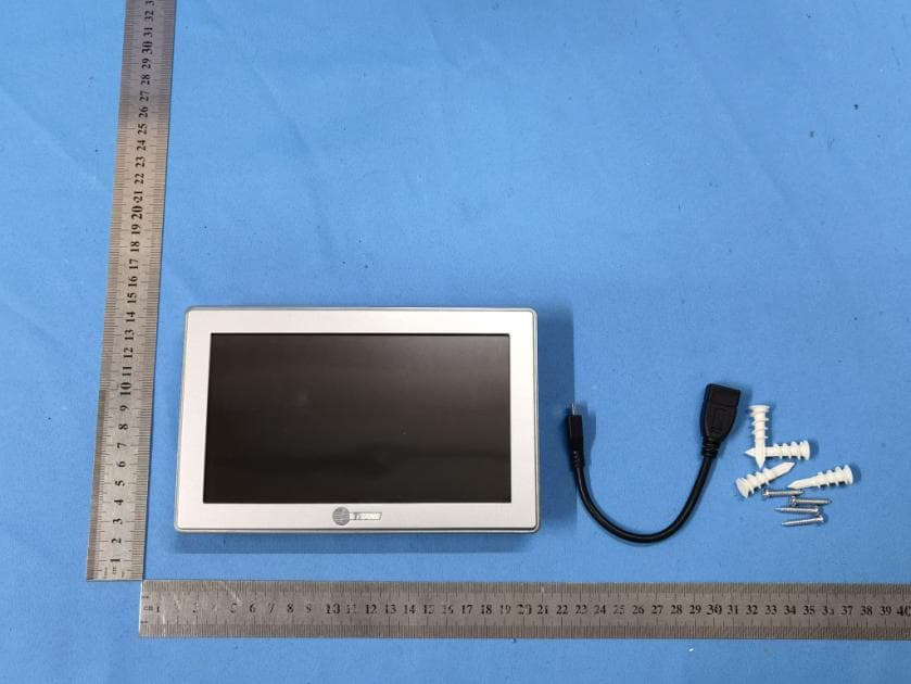
XVRZON1054
Dec 12, 2022COLOR WIFI Z-WAVE THERMOSTAT
Equipment Class
DTS - Digital Transmission System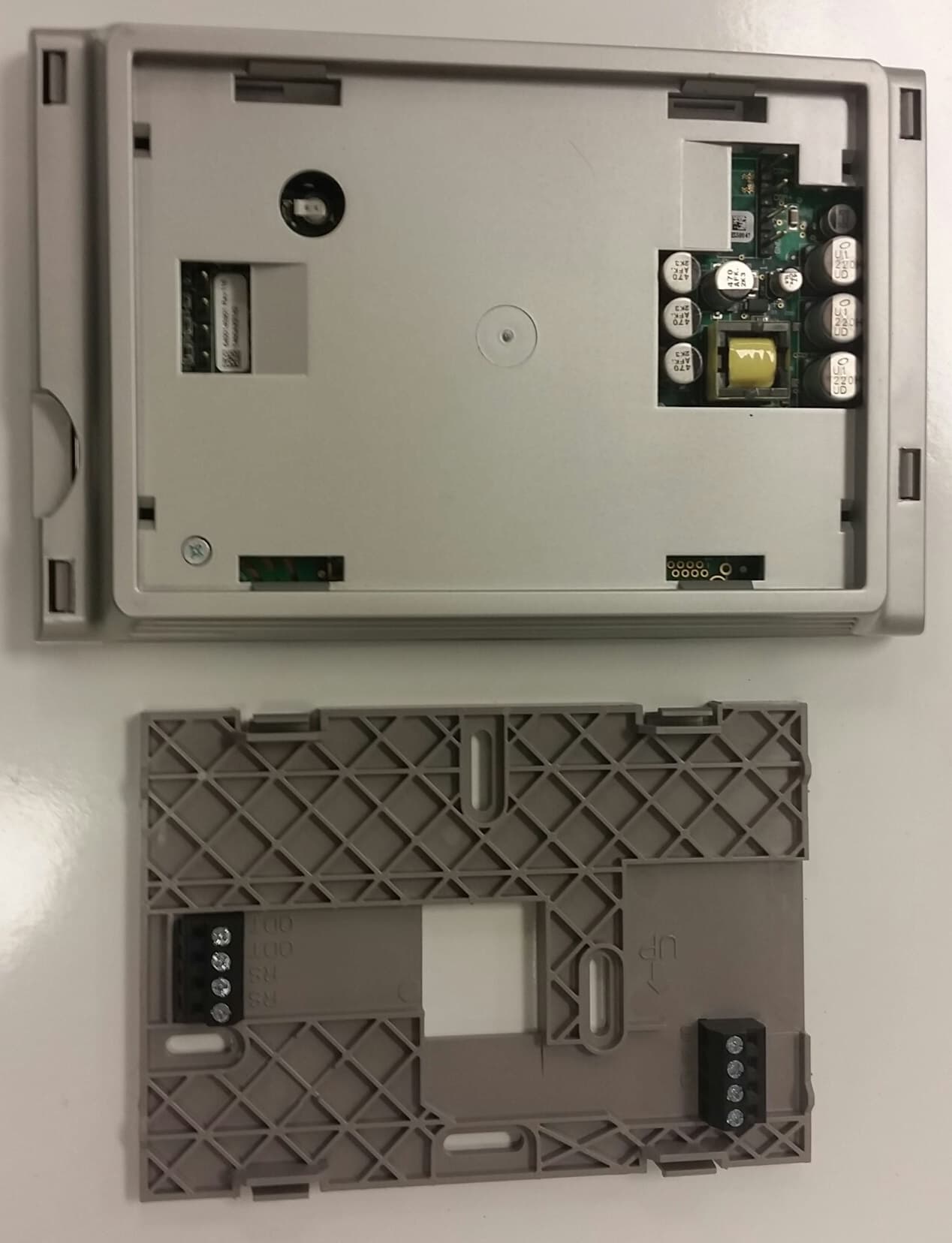
XVRZONE950B
Jan 29, 2015Smart Thermostat with Wireless Control
Equipment Class
DTS - Digital Transmission System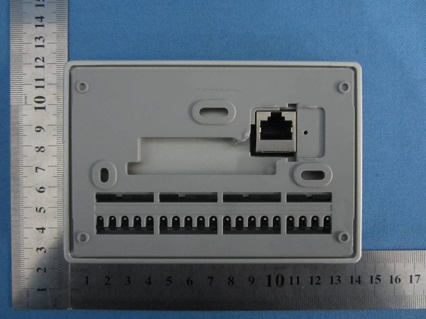
XVR-CONT8241
Jan 10, 2014Color Touchscreen Wi-Fi
Equipment Class
DTS - Digital Transmission System