XVRZONE950BSmart Thermostat with Wireless Control
Trane US, Inc.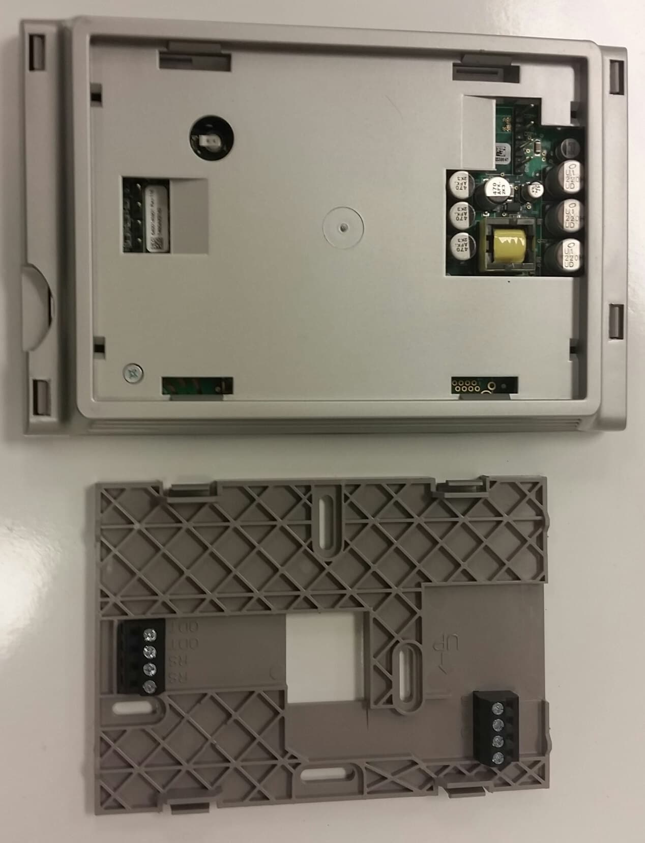
Click to zoom
Application Details
- Equipment Class
- DTS - Digital Transmission System
- Date of Grant
- Jan 29, 2015
- Application Purpose
- Original Equipment
- Date of Application
- Jan 28, 2015
- Equipment Note
- Smart Thermostat with Wireless Control
- Frequency Range
- 2412.00000000 - 2462.00000000
- Company
- Trane US, Inc.
- Country
- United States
Documents & Files
Document Text
Text extracted from the exhibit documents filed with the FCC. Open a document above to read the original.
Users Manual
User’s Guide AccuLink ™ Platinum 950 Control 2 Features Include... • Nexia™ Home Intelligence included • Weather Forecast (via wireless home network) • Easy to program • Allergy Clean/Quick Clean Cycles • Interactive Touchscreen • 1-Touch Presets • Built-in Help Screens • Operating Runtime Analysis • System Alerts • Lock Screen Security • Custom Screen Options • Screen Savers • Ten Year Registered Warranty Amazingly versatile, incredibly advanced The AccuLink ™ control integrates home comfort into your personal lifestyle like nothing you’ve ever seen before. 3 Easy to use The simple design and easy to follow functions of this control make it the most intuitive and easy to use control available. Just touch the screen to try out the functionality and make opera- tional changes to the system in your home. Help System On-screen notes provide addition- al details. When more information is needed, context sensitive help is only a button touch away. Scheduling Scheduling setup is made easy with the use of an on-screen wizard that walks you through the process. 1-Touch Presets Cooling and Heating presets al- low you to change your in-home temperatures with the touch of a button. Use only your fingertips to touch the touchscreen. Using any other implement can damage the screen. CAUTION ! Use only a soft damp cloth to clean the screen. CAUTION ! Customizable Customize the screen to suit your unique needs. You can setup shortcuts and an easy access dashboard on the Home screen. You can change the colors, and enjoy a photo slideshow. Table of Contents Introduction ...............................................1-4 Buttons and Navigations ..............................5 System, Fan, & Air Cleaner Modes ..........6-7 Scheduling/Programming .........................8-9 Loading and Viewing Photos ................10-11 Screen Saver Settings ...............................12 Commonly Used Features .........................13 Naming your System .................................13 Dealer Information Screen .........................13 Setting Time and Date ...............................14 Security Options ........................................14 Runtime History .........................................14 1-Touch Presets .........................................14 Customize Your Home Screen ...................15 Humidity .....................................................15 Wireless Network Setup .......................16-19 Advanced Networking Information ........20-23 Wireless Registration ............................26-27 Nexia™ Home Ingelligence Enrollment .....27 Software Upgrades ....................................28 Troubleshooting ....................................29-30 Network Diagnostics ..................................31 Warranty ....................................................32 4 Choose the shortcut items that show in this menu bar See and adjust zones Change settings with just a few button touches Manually change setpoints or use convenient Home, Away and Sleep presets View big, bold at-a-glance system status See current system status Use context sensitive help Choose the dashboard items that show in this section Easy to use... Everything is just a touch away 5 Buttons and Navigation 1 Pressing a button will display additional information or a new menu screen. EXAMPLE: You may access the Menu screen by pressing the “Menu” button on the home screen. You may access the Settings Menu by pressing the “Settings” button from the Menu screen. EXAMPLE: In the following sections, button sequenc- es will be shown with icons. For example, the se- quence on this page would be represented this way: 6 System ON/OFF, Mode Selection 2 Mode Selection To the right of the Menu button are 3 Mode buttons: 1) The first sets System Mode (including OFF). 2) The second controls Fan Mode. 3) The third controls Air Cleaner Mode. Each button has mode options to choose from. The chosen mode is conveniently displayed on its home screen button so you can see the functions your system is performing. 1) System Mode The “Auto” System Mode will switch between heating and cooling automatically. “Heating” and “Cooling” modes are dedicated modes. For example, you may wish to set your sys- tem to “Heating” in winter months so your cooling unit does not run. Likewise, you may wish to set your system to “Cooling” in summer months so that your furnace does not run. To completely turn off your system, select “Off”. 2) Fan Mode In “Auto” Fan Mode the sys- tem’s fan will run only when the system runs. The fan will run continuously when the Fan Mode is set to “On”. The “Circulate” Fan Mode will run the fan at least 10- 55 minutes out of every hour, decreasing hot/cool spots throughout your house. 7 Setpoint Panel 3 3) Air Cleaner Mode Automatic means the air cleaner will run when the fan runs. Quick Clean is a full power air cleaning cycle that increases the system fan speed setting (when not actively heating or cooling) to 100% for three hours to achieve maximum clean air delivery rate. Allergy Clean is a full power air cleaning cycle that increases the system fan speed setting (when not actively heating or cooling) to 100% for 24 hours to achieve maximum clean air delivery rate. Selecting “Ventilation” allows the user to temporarily override the programmed run-time. Cooling Setpoint PanelHeating Setpoint Panel Raise Lower To adjust the Heating Setpoint, select “Heating” and raise or lower the temperature to reach your desired setpoint. To adjust the Cooling Setpoint, select “Cooling” and raise or lower the temperature to reach your desired setpoint. A Setpoint is the desired temperature you would like your home heated or cooled to when in one of the three System Modes. 8 Manually Set up a Schedule 4 1) Turn Scheduling On (and select Manual Scheduling) 2) Enter the Schedule Menu 3) Select a day or time period By default the schedule shows the periods Wake, Away, Home and Sleep. Each day can have its own schedule and each sche…
Text truncated - open the document above for the full version.
Users Manual
18 The signal strength is indicated in bars. The more bars, the better the signal strength. A minimum of three bars is required for stable network operation. The network will op- erate with one or two bars, but may result in intermittent or lost connections. NOTE: Signal strength may be affected by router model, interference, obstructions and distance from the router. Consult router documentation for additional information. Available broadcasting networks with an adequate signal strength will display their SSIDs (Service Set IDentifiers) in this screen. A closed lock icon next to the SSID indicates a secure network. An open lock indicates a non-secure, “open” network. Select your network and press “Connect”. If a “Network Not Found” message is displayed, verify the wireless network is function- ing and within range. Consult router documentation for additional information. Signal Strength Indicators IndicatorBars (Color)Description One (Red)Very Weak Two (Yellow)Weak Three (Green)Strong Four (Green)Very Strong Selecting a Network7.2 19 1A) If the network is unsecured (with an “open” padlock), the following mes- sage will be dis- played. 2) Enter the network key (case-sensitive password). You or your network administrator will need to provide the required informa- tion. 1B) If the network is secured (with a “closed” padlock), the following mes- sage will be dis- played. 3) The control will connect to the wireless network. 4) When the control has successfully joined the wire- less network, the name of the network will be displayed with a green dot to the left and a signal strength indicator to the right. Enter Network Key/Password7.3 20 Advanced networking will be required in the following two instances: 1. When connecting to a non-broadcast network 2. When configuring a static IP address Advanced Networking Information7.4 Enter the Advanced Network Setup Menu. IMPORTANT: The Advanced Network screens are intended for individuals with networking familiarity. You or your network administrator will need to provide the required information. If any of this information is unknown or for questions specific to the wireless router, please consult the router documentation or your network administrator. 21 6) Enter the Network Key using the on-screen keypad. 5) Press “Enter Network Key” button. 2) Press the “Enter SSID Name” button.1) The “Network Security” button in this Ad- vanced Network Settings menu will be highlighted by default. 4) Select a network security type.* *NOTE: WEP-Shared is not supported. 3) Enter the SSID Name using the on-screen keypad. When the network’s SSID is not broadcast (hidden), manual configuration in this screen is required. Network Security7.5 22 Host Settings7.6 This screen is used to manage how the control obtains network addresses and is needed when DHCP (Dynamic Host Configuration Protocol) has been turned off or is not available on the router. Otherwise, you may use DHCP to automatically obtain this information. This manual configuration is required if a static IP address is desired. NOTE: No additional configuration may be required in a non-broadcast network where IP addresses are assigned by DHCP. You may connect to the network without modifying the Host Settings. 3) Enter the IP address as required for each. 4) To manually select a DNS server, enter IP address(es). 1) Select the “Host Settings” button to access the second screen of settings in this Ad- vanced Network Settings menu. 2) Select IP Address, Gateway and Subnet Mask buttons as required. 5) After all the addresses are assigned, Con- nect to the network. 6) To change a Static IP Address to a DHCP Ad- dress, press “Release and Renew IP Address”. 23 Once a network has been joined, the control will reconnect to it after signal or power interruptions. When connected, a green dot will be shown. To disconnect from this network, enter the “Connect to a Network” menu and select “Disconnect”. NOTE: When joining a different network, the current router must be discon- nected in this menu before a new one may be selected. In addition if settings are changed on the owner’s router, the network may need to be disconnected and reconnected in this menu. Repeat previous steps to connect to a different network. The Network Properties screen displays the control’s current network informa- tion. Network Properties Disconnecting from a Network 7.7 7.8 24 Zoned Environments7.9 2) The Zone Menu is shown at right. 4) The Zone Overview menu shows a quick view of each zone’s current condition. 3) In zoned environments, the main screen display will change to indicate the presence of mul- tiple zones. (Notice the new zone button—la- beled “Upstairs”—at right.) Arrow buttons navigate between zone views. 1) In a zoned environ- ment, the “Zones” but- ton will appear in place of the “System” button (see picture at right). 25 5) System wide settings for all zones can be seen at a glance in the System Status screen. 8) System and Zone Names may be set in the Zone Names screen. The “Rename System” and “Rename Zone” buttons al- low entering custom names from a keypad. Pre-configured names are also available. 6) A schedule for one zone can be copied to another. 7) Each zone’s schedule can be viewed by cy- cling through the zones using the arrows in the top left corner. 26 Wireless Registration 8 1A) In the Network Setup Screen, select the “Register Now” button to begin registration. Proceed to Step 2. 1B) If instead you try to connect to Weather before you have reg- istered, you will be prompted to register. 2) After reading and ac- cepting the License Agreement, enter your email address. 3) An email containing a verification code will automatically be sent to the email address you entered. Registration is required for Weather, Software Updates and linking two or more controls together. Registration ensures that your control is using the most up-to-date software and will also let you take advantage of exciting new features in the future. You…
Text truncated - open the document above for the full version.
Users Manual
User’s Guide ComfortLink ™ II XL950 Control 2 Features Include... • Nexia™ Home Intelligence included • Weather Forecast (via wireless home network) • Easy to program • Allergy Clean/Quick Clean Cycles • Interactive Touchscreen • 1-Touch Presets • Built-in Help Screens • Operating Runtime Analysis • System Alerts • Lock Screen Security • Custom Screen Options • Screen Savers • Ten Year Registered Warranty The ComfortLink ™ II control integrates home comfort into your personal lifestyle like nothing you’ve ever seen before. Amazingly versatile, incredibly advanced 3 Easy to use The simple design and easy to follow functions of this control make it the most intuitive and easy to use control available. Just touch the screen to try out the functionality and make opera- tional changes to the system in your home. Help System On-screen notes provide addition- al details. When more information is needed, context sensitive help is only a button touch away. Scheduling Scheduling setup is made easy with the use of an on-screen wizard that walks you through the process. 1-Touch Presets Cooling and Heating presets al- low you to change your in-home temperatures with the touch of a button. Use only your fingertips to touch the touchscreen. Using any other implement can damage the screen. CAUTION ! Use only a soft damp cloth to clean the screen. CAUTION ! Customizable Customize the screen to suit your unique needs. You can setup shortcuts and an easy access dashboard on the Home screen. You can change the colors, and enjoy a photo slideshow. Table of Contents Introduction ...............................................1-4 Buttons and Navigations ..............................5 System, Fan, & Air Cleaner Modes ..........6-7 Scheduling/Programming .........................8-9 Loading and Viewing Photos ................10-11 Screen Saver Settings ...............................12 Commonly Used Features .........................13 Naming your System .................................13 Dealer Information Screen .........................13 Setting Time and Date ...............................14 Security Options ........................................14 Runtime History .........................................14 1-Touch Presets .........................................14 Customize Your Home Screen ...................15 Humidity .....................................................15 Wireless Network Setup .......................16-19 Advanced Networking Information ........20-23 Wireless Registration ............................26-27 Nexia™ Home Ingelligence Enrollment .....27 Software Upgrades ....................................28 Troubleshooting ....................................29-30 Network Diagnostics ..................................31 Warranty ....................................................32 4 Choose the shortcut items that show in this menu bar See and adjust zones Change settings with just a few button touches Manually change setpoints or use convenient Home, Away and Sleep presets View big, bold at-a-glance system status See current system status Use context sensitive help Choose the dashboard items that show in this section Easy to use... Everything is just a touch away 5 Buttons and Navigation 1 Pressing a button will display additional information or a new menu screen. EXAMPLE: You may access the Menu screen by pressing the “Menu” button on the home screen. You may access the Settings Menu by pressing the “Settings” button from the Menu screen. EXAMPLE: In the following sections, button sequenc- es will be shown with icons. For example, the se- quence on this page would be represented this way: 6 System ON/OFF, Mode Selection 2 Mode Selection To the right of the Menu button are 3 Mode buttons: 1) The first sets System Mode (including OFF). 2) The second controls Fan Mode. 3) The third controls Air Cleaner Mode. Each button has mode options to choose from. The chosen mode is conveniently displayed on its home screen button so you can see the functions your system is performing. 1) System Mode The “Auto” System Mode will switch between heating and cooling automatically. “Heating” and “Cooling” modes are dedicated modes. For example, you may wish to set your sys- tem to “Heating” in winter months so your cooling unit does not run. Likewise, you may wish to set your system to “Cooling” in summer months so that your furnace does not run. To completely turn off your system, select “Off”. 2) Fan Mode In “Auto” Fan Mode the sys- tem’s fan will run only when the system runs. The fan will run continuously when the Fan Mode is set to “On”. The “Circulate” Fan Mode will run the fan at least 10- 55 minutes out of every hour, decreasing hot/cool spots throughout your house. 7 Setpoint Panel 3 3) Air Cleaner Mode Automatic means the air cleaner will run when the fan runs. Quick Clean is a full power air cleaning cycle that increases the system fan speed setting (when not actively heating or cooling) to 100% for three hours to achieve maximum clean air delivery rate. Allergy Clean is a full power air cleaning cycle that increases the system fan speed setting (when not actively heating or cooling) to 100% for 24 hours to achieve maximum clean air delivery rate. Selecting “Ventilation” allows the user to temporarily override the programmed run-time. Cooling Setpoint PanelHeating Setpoint Panel Raise Lower To adjust the Heating Setpoint, select “Heating” and raise or lower the temperature to reach your desired setpoint. To adjust the Cooling Setpoint, select “Cooling” and raise or lower the temperature to reach your desired setpoint. A Setpoint is the desired temperature you would like your home heated or cooled to when in one of the three System Modes. 8 Manually Set up a Schedule 4 1) Turn Scheduling On (and select Manual Scheduling) 2) Enter the Schedule Menu 3) Select a day or time period By default the schedule shows the periods Wake, Away, Home and Sleep. Each day can have its own schedule and each…
Text truncated - open the document above for the full version.
Users Manual
18 The signal strength is indicated in bars. The more bars, the better the signal strength. A minimum of three bars is required for stable network operation. The network will op- erate with one or two bars, but may result in intermittent or lost connections. NOTE: Signal strength may be affected by router model, interference, obstructions and distance from the router. Consult router documentation for additional information. Available broadcasting networks with an adequate signal strength will display their SSIDs (Service Set IDentifiers) in this screen. A closed lock icon next to the SSID indicates a secure network. An open lock indicates a non-secure, “open” network. Select your network and press “Connect”. If a “Network Not Found” message is displayed, verify the wireless network is function- ing and within range. Consult router documentation for additional information. Signal Strength Indicators IndicatorBars (Color)Description One (Red)Very Weak Two (Yellow)Weak Three (Green)Strong Four (Green)Very Strong Selecting a Network7.2 19 1A) If the network is unsecured (with an “open” padlock), the following mes- sage will be dis- played. 2) Enter the network key (case-sensitive password). You or your network administrator will need to provide the required informa- tion. 1B) If the network is secured (with a “closed” padlock), the following mes- sage will be dis- played. 3) The control will connect to the wireless network. 4) When the control has successfully joined the wire- less network, the name of the network will be displayed with a green dot to the left and a signal strength indicator to the right. Enter Network Key/Password7.3 20 Advanced networking will be required in the following two instances: 1. When connecting to a non-broadcast network 2. When configuring a static IP address Advanced Networking Information7.4 Enter the Advanced Network Setup Menu. IMPORTANT: The Advanced Network screens are intended for individuals with networking familiarity. You or your network administrator will need to provide the required information. If any of this information is unknown or for questions specific to the wireless router, please consult the router documentation or your network administrator. 21 6) Enter the Network Key using the on-screen keypad. 5) Press “Enter Network Key” button. 2) Press the “Enter SSID Name” button.1) The “Network Security” button in this Ad- vanced Network Settings menu will be highlighted by default. 4) Select a network security type.* *NOTE: WEP-Shared is not supported. 3) Enter the SSID Name using the on-screen keypad. When the network’s SSID is not broadcast (hidden), manual configuration in this screen is required. Network Security7.5 22 Host Settings7.6 This screen is used to manage how the control obtains network addresses and is needed when DHCP (Dynamic Host Configuration Protocol) has been turned off or is not available on the router. Otherwise, you may use DHCP to automatically obtain this information. This manual configuration is required if a static IP address is desired. NOTE: No additional configuration may be required in a non-broadcast network where IP addresses are assigned by DHCP. You may connect to the network without modifying the Host Settings. 3) Enter the IP address as required for each. 4) To manually select a DNS server, enter IP address(es). 1) Select the “Host Settings” button to access the second screen of settings in this Ad- vanced Network Settings menu. 2) Select IP Address, Gateway and Subnet Mask buttons as required. 5) After all the addresses are assigned, Con- nect to the network. 6) To change a Static IP Address to a DHCP Ad- dress, press “Release and Renew IP Address”. 23 Once a network has been joined, the control will reconnect to it after signal or power interruptions. When connected, a green dot will be shown. To disconnect from this network, enter the “Connect to a Network” menu and select “Disconnect”. NOTE: When joining a different network, the current router must be discon- nected in this menu before a new one may be selected. In addition if settings are changed on the owner’s router, the network may need to be disconnected and reconnected in this menu. Repeat previous steps to connect to a different network. The Network Properties screen displays the control’s current network informa- tion. Network Properties Disconnecting from a Network 7.7 7.8 24 Zoned Environments7.9 2) The Zone Menu is shown at right. 4) The Zone Overview menu shows a quick view of each zone’s current condition. 3) In zoned environments, the main screen display will change to indicate the presence of mul- tiple zones. (Notice the new zone button—la- beled “Upstairs”—at right.) Arrow buttons navigate between zone views. 1) In a zoned environ- ment, the “Zones” but- ton will appear in place of the “System” button (see picture at right). 25 5) System wide settings for all zones can be seen at a glance in the System Status screen. 8) System and Zone Names may be set in the Zone Names screen. The “Rename System” and “Rename Zone” buttons al- low entering custom names from a keypad. Pre-configured names are also available. 6) A schedule for one zone can be copied to another. 7) Each zone’s schedule can be viewed by cy- cling through the zones using the arrows in the top left corner. 26 Wireless Registration 8 1A) In the Network Setup Screen, select the “Register Now” button to begin registration. Proceed to Step 2. 1B) If instead you try to connect to Weather before you have reg- istered, you will be prompted to register. 2) After reading and ac- cepting the License Agreement, enter your email address. 3) An email containing a verification code will automatically be sent to the email address you entered. Registration is required for Weather, Software Updates and Nexia™ Home Ingelligence integration. Registration ensures that your control is using the most up-to-date software and will also let you take advantage of exciting new features in the future. You …
Text truncated - open the document above for the full version.
External Photos
16536 External Photographs Page 1 of 7 16536 External Photographs Page 2 of 7 16536 External Photographs Page 3 of 7 16536 External Photographs Page 4 of 7 16536 External Photographs Page 5 of 7 16536 External Photographs Page 6 of 7 16536 External Photographs Page 7 of 7
ID Label/Location Info
16536 Label Location Page 1 of 1 Label Location is Denoted (8) Above
Internal Photos
16536 Internal Photographs Page 1 of 4 16536 Internal Photographs Page 2 of 4 16536 Internal Photographs Page 3 of 4 16536 Internal Photographs Page 4 of 4
RF Exposure Info
16536 Exposure Supplemental Report Rev01 Page 1 of 2 Professional Testing (EMI) Inc. 1601 North A.W. Grimes Blvd., Suite B Round Rock, TX 78665 e-mail: [email protected] (512) 244-3371 Fax: (512) 244-1846 1.0 Maximum Permissible Exposure Evaluation (Supplements the test report.) The measured power is considered for the intended use of the device and resulting RF exposure to the user. 1.2 Criteria Section Reference Date KDB 447498 D01 Mobile Portable RF Exposure v05r01 // RSS‐102 Issue 4 March 2010, Notice 2013 DRS0911 2015‐01‐23 1.3 Procedure Using measurement of peak power and considering the intended application, determine the permissible exposure level, applicability of exclusion, or whether additional exposure tests (SAR) are indicated. When applicable justify conclusion for selected exposure level and separation distance. 1.4 Power to Exposure Calculation Highest operating frequency is 2462 MHz. Power is determined from the measured field strength and with antenna gain included by default. Due to low fundamental power the source duty cycle was not evaluated. SAR exemption method was applied. Table 1.4.1 Power Calculation for Exposure Measured Field Strength dBμV/m at 3 m (Peak Detection) Calculated Peak EIRP dBm Source Duty Cycle Factor dB Calculated Average EIRP dBm EIRP In Linear Terms mW 90.8 ‐4.4 0.0 ‐4.4 0.361 1.5 SAR Exemption Calculation – 3.0 Criteria Calculation (max power including tune up tolerance = 0.361 mW): [(0.361 mW)/(20 mm)] · [√2.462 (GHz)] = 0.0283 0.0283 ≤ 3.0 Therefore, the device meets the applicable FCC SAR exemption requirements. This device meets the SAR Evaluation Exemption criteria in RSS-102 Clause 2.5.1, based on the output power being less than 20mW for general public use (2.2 GHz – 3.0 GHz). 16536 Exposure Supplemental Report Rev01 Page 2 of 2 Professional Testing (EMI) Inc. Signed: Eric Lifsey ***
Test Report
1601 North A.W. Grimes Blvd., Suite B Round Rock, TX 78665 e-mail: [email protected] (512) 244-3371 Fax: (512) 244-1846 January 23, 2015 Sanchali Deb Ingersoll Rand 6200 Troup Highway Tyler, TX 75701 Sanchali: Thank you for allowing Professional Testing (EMI), Inc. an opportunity to perform testing for Ingersoll Rand. Enclosed is the Wireless Certification Report for the AZONE950AC52Z. This report can be used to demonstrate compliance with requirements for wireless devices in North America. If you have any questions, please contact me. Sincerely, Jeffrey A. Lenk President Attachment Ingersoll Rand – AZONE950AC52Z, TZONE950AC52Z 16536 Professional Testing (EMI) Inc. Page 2 of 60 Project 16536-15 Ingersoll Rand AZONE950AC52Z TZONE950AC52Z Wireless Certification Report Prepared for: Sanchali Deb Ingersoll Rand 6200 Troup Highway Tyler, TX 75701 By Professional Testing (EMI), Inc. 1601 North A.W. Grimes Blvd., Suite B Round Rock, Texas 78665 January 23, 2015 Reviewed by Written by Larry Finn Chief Technical Officer Eric Lifsey Test Engineer Ingersoll Rand – AZONE950AC52Z, TZONE950AC52Z 16536 Professional Testing (EMI) Inc. Page 3 of 60 Revision History Revision Number Description Date 00 Draft for client and internal review. January 19, 2015 01 Draft revised with client and internal review changes. January 20, 2015 02 Draft revised with new model information. January 23, 2015 02 Released. January 26, 2015 03 Revised per comments of TCB. January 28, 2015 Ingersoll Rand – AZONE950AC52Z, TZONE950AC52Z 16536 Professional Testing (EMI) Inc. Page 4 of 60 Table of Contents Revision History ............................................................................................................................................................. 3 Compliance Certificate .................................................................................................................................................. 6 1.0 Introduction .......................................................................................................................................................... 7 1.1 Scope ............................................................................................................................................................... 7 1.2 EUT Description ............................................................................................................................................. 7 1.3 EUT Operation ................................................................................................................................................ 7 1.4 Modifications to Equipment ............................................................................................................................ 7 1.5 Test Site .......................................................................................................................................................... 8 1.6 Applicable Documents and Clauses ................................................................................................................ 8 2.0 Fundamental Power ............................................................................................................................................. 9 2.1 Test Procedure ................................................................................................................................................ 9 2.2 Test Criteria .................................................................................................................................................... 9 2.3 Test Results .............................…
Text truncated - open the document above for the full version.
Contact Information
Applicant
Bradley Thomas Wilson(Embedded Controls Hardware Engineering Manager)
Test Firm
Professional Testing (EMI), Inc.Larry Finn
Technical Specifications
| # | Rule Parts | Frequency Range | Power Output |
|---|---|---|---|
| 1 | 15C | 2.41 GHz - 2.46 GHz | 361.00 µW |
Other Applications from Trane US, Inc.
XVREHMID1
Jul 03, 2026HVAC Performance Monitoring Kit
Equipment Class
DTS - Digital Transmission SystemXVREHMOD1
Jul 03, 2026HVAC Performance Monitoring Kit
Equipment Class
DTS - Digital Transmission System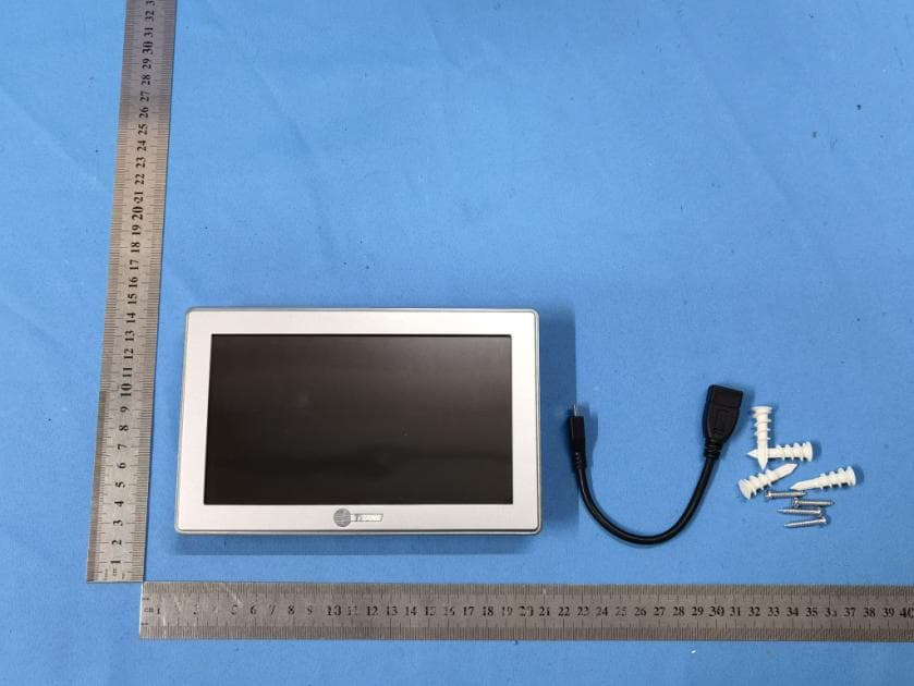
XVRZON1054
Dec 12, 2022COLOR WIFI Z-WAVE THERMOSTAT
Equipment Class
DTS - Digital Transmission System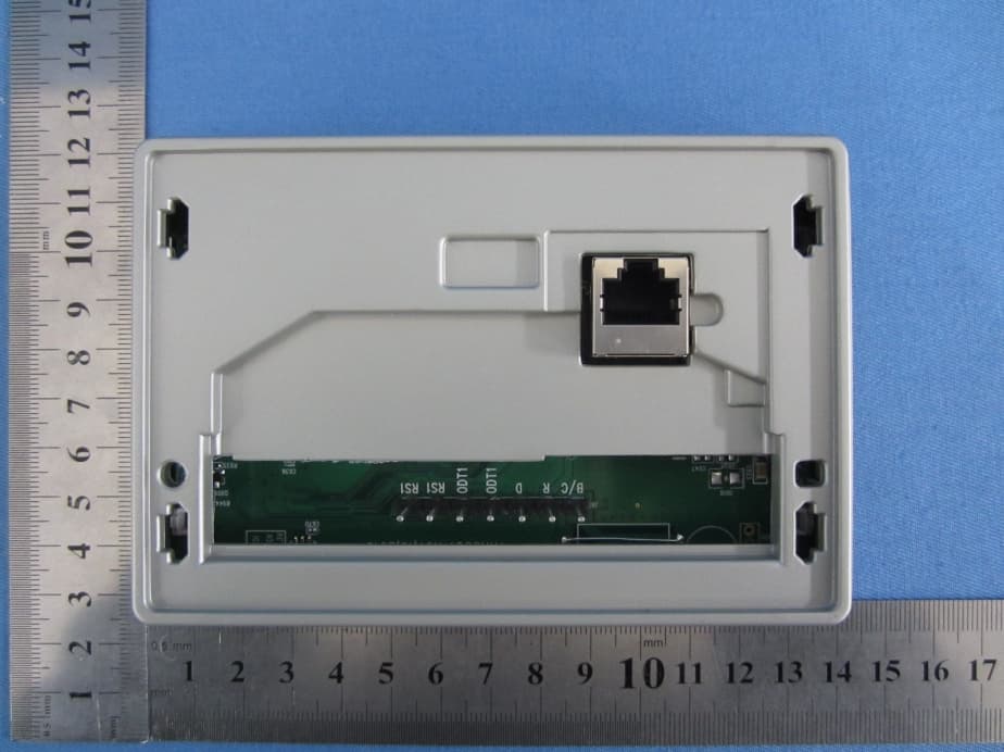
XVR-CONT8501
Apr 01, 2014Color Touchscreen Wi-Fi Thermostat
Equipment Class
DTS - Digital Transmission System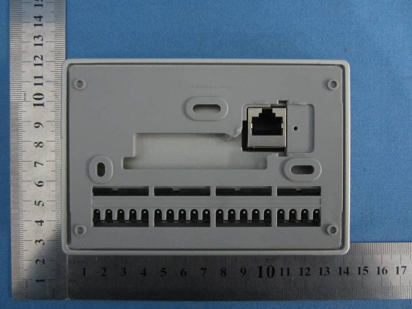
XVR-CONT8241
Jan 10, 2014Color Touchscreen Wi-Fi
Equipment Class
DTS - Digital Transmission System