XYCARAMO-SMARTPORTABLE SKIN DIAGNOSIS SYSTEM
Aram Huvis Co.,LTD.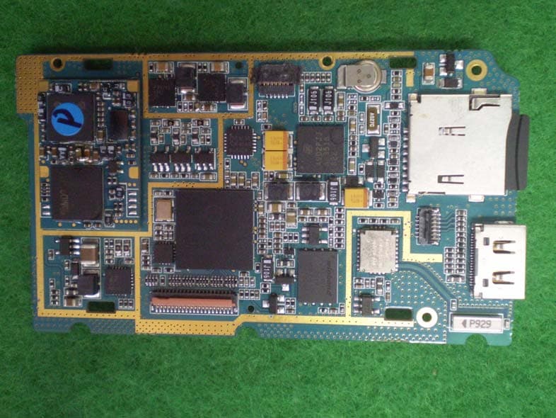
Click to zoom
Application Details
- Equipment Class
- DSS - Part 15 Spread Spectrum Transmitter
- Date of Grant
- Jan 13, 2010
- Application Purpose
- Original Equipment
- Date of Application
- Jan 12, 2010
- Equipment Note
- PORTABLE SKIN DIAGNOSIS SYSTEM
- Frequency Range
- 2402.00000000 - 2480.00000000
- Company
- Aram Huvis Co.,LTD.
- Country
- South Korea
Documents & Files
Document Text
Text extracted from the exhibit documents filed with the FCC. Open a document above to read the original.
Users Manual
2 5 5431 Key function 1. Power button Press it to “ON”Press & hold it for 5sec to “OFF” 2. Mode change button To change diagnosis processMoisture -> Wrinkle (30X) -> Evenness (60X) - > Pore (60X) -> Pigmentation (60X PL) -> 1X lens 3. LED light mode change button Only used in 1X lens mode In the album, it is move key to select another image 4. Go to Album button When camera is activated, press this and the captured image will be shown as a album In the album, it is move key to select anotherimage 5. Capture button Click to capture and re-activate the camera When it is searching for Blue tooth device. 6. Bluetooth sending button It is used in Album to send selected image to external device 7. Delete button It is used in Album to delete selected image 6 7 Auto-focus function- press “5”.Capture – press “5” for 2 sec. 2 Moisture CheckTo check moisture,Simply place moisture sensor area to skin And press button 3.There are four round shaped metal in the lens part, above two metals “1” aremoisture sensorThe test result will be displaced as shown as “2” 2 1 moisture sensor 3 Please press “M” button to move to next step. 3 Wrinkle Check Capture the image by “1”Re-activate & re-capture press “1” Diagnosis process will be done in 1) PDA ( which has Blue tooth )2) PC ( Blue tooth )Or captured image will be saved in external memory such as SD or Mini SD card then it can be inserted into PC to perform the analysis Diagnosis software can be provided – depends on project. 1 1 Please press “M” button to move to next step. X30 Auto-focus function- press “1”.Capture – press “1” for 2 sec. 4 Album ( 4 images view )Captured image i s saved in Album Go to Album, press “3” when the camera is activating When album is shown, “4” images will shown Press “1” selected image will be shown in “Full Screen”In 4 images view, press “2” or “3” to selectother imagesIn 4 images view & one image view, press “4” to transfer the image to external device and press “5” to delete selected image 23 4 1 5 5 Album ( 1 images view ) Captured image i s saved in Album Go to Album, press “3” when the camera is activating When album is shown, “4” images will shown Press “1” selected image will be shown in “Full Screen”In 4 images view, press “2” or “3” to selectother imagesIn 4 images view & one image view, press “4” to transfer the image to external device and press “5” to delete selected image 23 4 1 5 6 Evenness Check From “Wrinkle” check to “Evenness” check process, press “M” to changeCapture the image by “2”Re-activate & re-capture press “2” 12 2 Please press “M” button to move to next step. X60 7 Pore Check From “Evenness” check to “Pore” check process, press “M” to changeCapture the image by “2”Re-activate & re-capture press “2” 2 2 Please press “M” button to move to next step. X60 8 Spot Check From “Pore” check to “Spot” check process, press “M” to changeCapture the image by “2”Re-activate & re-capture press “2” 2 2 Please press “M” button to move to next step. X60- Polarizing mode 9 Client’s profile From “Spot” check to “X1 lens to take client picture”. process, press “M” to changeCapture the image by “2”Re-activate & re-capture press “2” Please press “M” button to move to first step. 2 X1 10 Operating frequency: 2400-2483.5 MHzOperating voltage : DC 3.7V Li-ion Battery Operating temperature : -10°C ~ 50°C Federal Communication Commission Interference Statement This equipment has been tested and found to comply with the limits for a Class B digital device, pursuant to Part 15 of the FCC Rules. These limits are designed to provide reasonable protection against harmful interference in a residential installation. This equipment generates, uses and can radiate radio frequency energy and, if not installed and used in accordance with the instructions, may cause harmful interference to radio communications. However, there is no guarantee that interference will not occur in a particular installation. If this equipment does cause harmful interference to radio or television reception, which can be determined by turning the equipment off and on, the user is encouraged to try to correct the interference by one of the following measures: • Reorient or relocate the receiving antenna. • Increase the separation between the equipment and receiver. • Connect the equipment into an outlet on a circuit different from that to which the receiver is con-nected. • Consult the dealer or an experienced radio/TV technician for help. FCC Caution: To assure continued compliance, (example - use only shielded interface cables when connecting to computer or peripheral devices). Any changes or modifications not expressly approved by the party responsible for compliance could void the user’s authority to operate this equipment.This device complies with Part 15 of the FCC Rules. Operation is subject to the following two conditions: (1) This device may not cause harmful interference, and (2) this device must accept any interference received, including interference that may cause undesired operation including interference that may cause undesired operation IMPORTANT NOTE: FCC RF Radiation Exposure Statement: This equipment complies with FCC RF radiation exposure limits set forth for an uncontrolled environment. This equipment should be installed and operated with a minimum distance of 20 centimeters between the radiator and your body.This transmitter must not be co-located or operating in conjunction with any other antenna or transmitter. NOTE: THE MANUFACTURER IS NOT RESPONSIBLE FOR ANY RADIO OR TV INTERFERENCE CAUSED BY UNAUTHORIZED MODIFICATIONS TO THIS EQUIPMENT. SUCH MODIFICATIONS COULD VOIDTHE USER�S AUTHORITY TO OPERATE THE EQUIPMENT. IMPORTANT Safety Instruction: 1) Read these instructions. 2) Keep these instructions. 3) Heed all warnings. 4) Follow all instructions. 5) Do not use this equipment near water. 6) Do not using near any heat sources such as radiators, heat resisters, stove, or other equipment that produce heat.
Attestation Statements
801 Byucksan Technopia, 434-6 Sangdaewon-dong Sungnam-City, Kyungki-do, Korea Tel No : 82-31-732-6320 Fax No : 82-31-732-6330 ATTESTATION STATEMENT In re : Aram Huvis Co., Ltd. FCC ID : XYCARAMO-SMART January 05, 2010 15.247(a)(1) The hopping sequence must be pseudorandom all Channels are used equally on average the receiver input bandwidth is approximately equal to the transmit ba ndwidth the receiver hops in sequence with the transmitted signal 15.247(g) The system is designed to comply with all of the regulations in Section 15.247 when the transmitter is presented with a continuous data (or information) 15.247(h) The system does not coordinate its channel selection/hopping sequence with oth er frequency hopping systems for the express purpose of avoiding the simultane ous occupancy of individual hopping frequencies by multiple transmitters. Sincerely, _______________________ Kyu-Chul, Shin - Engineer THRU-KES CO.,LTD. cc. Chang Won,Kim /Manager
Cover Letter(s)
E-Mail : [email protected] Tel. : 82-31-732-6320 Fax. : 82-31-732-6330 January 05, 2010 Federal Communications Commission Authorization and Evaluation Division Confidentiality Request regarding application for certification of FCC ID: XYCARAMO-SMART Pursuant to Sections 0.457 and 0.459 of the Commission’s Rules, we hereby request confidential treatment of information accompanying this application as outlined below: Exhibit Type File Name Part List CONF APPENDIX – ARAMO-SMART - Part List.PDF Schematics Diagram(s) CONF APPENDIX - ARAMO-SMART – Schemetics.PDF Block diagram CONF APPENDIX - ARAMO-SMART – Block diagram.PDF The above materials contain trade secrets and proprietary information not customarily released to the public. The public disclosure of these materials may be harmful to the applicant and provide unjustified benefits to its competitors. The applicant understands that pursuant to Section 0.457 of the Rules, disclosure of this application and all accompanying documentation will not be made before the date of the Grant for this application. Sincerely, Aram Huvis Co., Ltd. Chang Won,Kim /Manager
Internal Photos
www.kes.co.kr EUT Internal Photographs www.kes.co.kr
Operational Description
Dielectric Chip Antenna ■ P/N ; ODBTPTR7020 ParameterLWTABCDEF Value[mm] 7.0 ±0.1 2.0 ±0.1 1.2 ±0.1 1.540.8 0.4 1.6 0.9 Unless Specified tolerances are ± 0.05 mm `Dielectric Chip Antenna ■ Test Result for ARAMO SMART 3D Peak gain (dBi) Average gain (dBi) Efficiency (%) 2400 [MHz]1.79-2.9650.73 2425 [MHz]2.40-2.4357.25 2445 [MHz]2.26-2.4656.91 2465 [MHz]2.53-2.2360.00 2485 [MHz]2.41-2.2160.23 ■ Radiation Pattern 3D 3D Radiation Pattern VSWR / Return Loss 1,4 번패드 2,3 번패드 동테잎으로 연결
Operational Description
BC417143B-ds-001Pg Production Information © Cambridge Silicon Radio Limited 2005 Page 1 of 116 _äìÉ`çêÉ»QJbñíÉêå~ä= Product Data Sheet _äìÉ`çêÉ»QJbñíÉêå~äDevice Features Product Data Sheet Production InformationCSR PLC2005 g2005BC417143B-ds-001P© 2005 Cambridge Silicon Radio Limited Fully Qualified Bluetooth v2.0+EDR Enhanced Data Rate (EDR) compliant with v2.0.E.2 of specification for both 2Mbps and 3Mbps modulation modes Full Speed Bluetooth Operation with Full Piconet Support Scatternet Support 1.8V core, 1.8 to 3.6V I/O Low Power 1.8V operation 8 x 8mm 96-ball TFBGA and 6 x 6mm 96-ball VFBGA Package options Minimum External Components Integrated 1.8V Regulator USB and Dual UART Ports Support for 802.11 Co-Existence Support for 8Mbit External Flash RoHS Compliant Single Chip Bluetooth ® v2.0+EDR System Production Information Data Sheet For BC417143B-IQN-E4 BC417143B-IRN-E4 July 2005 General DescriptionApplications _äìÉ`çêÉ » QJbñíÉêå~ä is a single chip radio and baseband IC for Bluetooth 2.4GHz systems including enhanced data rates (EDR) to 3Mbps. PCs Personal Digital Assistants (PDAs) Computer Accessories (compact Flash Cards, PCMCIA Cards, SD Cards and USB Dongles) Access Points Digital Cameras BC417143B interfaces to 8Mbit of external Flash memory. When used with the CSR Bluetooth software stack, it provides a fully compliant Bluetooth system to v2.0 of the specification for data and voice communications.. System Architecture BlueCore4-External has been designed to reduce the number of external components required which ensures production costs are minimised. The device incorporates auto-calibration and built in self test (BIST) routines to simplify development, type approval and production test. All hardware and device firmware is fully compliant with the Bluetooth v2.0 + EDR specification (all mandatory and optional features). To improve the performance of both Bluetooth and 802.11b/g co-located systems a wide range of co-existence features are available including two types of hardware signalling: basic activity signalling and Intel WCS activity and channel signalling. 2.4 GHz Radio I/O RF IN RF OUT RAM Baseband DSP MCU FLASH XTAL External Memory UART/ USB SPI PIO PCM BC417143B-ds-001Pg Production Information © Cambridge Silicon Radio Limited 2005 Page 2 of 116 _äìÉ`çêÉ»QJbñíÉêå~ä= Product Data Sheet Contents 1Status Information .......................................................................................................................................... 8 2Key Features .................................................................................................................................................... 9 3Package Information ..................................................................................................................................... 10 3.18 x 8mm TFBGA Package Information .................................................................................................. 10 3.2BC417143B-IQN-E4 Device Terminal Functions ..................................................................................11 3.36 x 6mm VFBGA Package Information .................................................................................................. 16 3.4BC417143B-IRN-E4 Device Terminal Functions ................................................................................... 17 4Electrical Characteristics ............................................................................................................................. 22 4.1Power Consumption .............................................................................................................................. 27 5Radio Characteristics - Basic Data Rate ..................................................................................................... 29 5.1Temperature +20°C ............................................................................................................................... 29 5.1.1Transmitter ................................................................................................................................ 29 5.1.2Receiver .................................................................................................................................... 31 5.2Temperature -40°C ................................................................................................................................ 33 5.2.1Transmitter ................................................................................................................................ 33 5.2.2Receiver .................................................................................................................................... 33 5.3Temperature -25°C ................................................................................................................................ 34 5.3.1Transmitter ................................................................................................................................ 34 5.3.2Receiver .................................................................................................................................... 34 5.4Temperature +85°C ............................................................................................................................... 35 5.4.1Transmitter ................................................................................................................................ 35 5.4.2Receiver .................................................................................................................................... 35 5.5Temperature +105°C ............................................................................................................................. 36 5.5.1Transmitter ................................................................................................................................ 36 5.5.2Receiver .......................…
Text truncated - open the document above for the full version.
Test Report
www.kes.co.kr Te s t Re p o r t N o. : TK-FR10001 Model No: ARAMO-SMART Page 1 of 39 This Report shall not be reproduced except in full without the written approval of THRU-KES CO.,LTD. TEST REPORT For FCC Test Report No. : TK-FR10001 Date of Issue : 01/11/2010 FCC ID : XYCARAMO-SMART Description of Product : Portable Skin Diagnosis System Model No. : ARAMO-SMART Applicant : Aram Huvis Co., Ltd. 801 Byucksan Technopia, 434-6 Sangdaewon-dong Sungnam-City, Kyungki-do, Korea Manufacturer : Aram Huvis Co., Ltd. 801 Byucksan Technopia, 434-6 Sangdaewon-dong Sungnam-City, Kyungki-do, Korea Standards : FCC Part 15.247 Test Date : 01/04/2010 – 01/11/2010 Test Results : PASS FAIL The test results relate only to the items tested. Tested by: Reviewed by: Kyu-Chul Shin KT Kang Test Engineer Technical Manager Date:01/11/2010 Date: 01/11/2010 THRU-KES CO.,LTD. 477-6, Hager-Ri, Yoju-Up, Yoju-Gun Kyunggi-Do,469-803, Korea Tel: +82-31-425-6200 / Fax: +82-31-424-0450 www.kes.co.kr Te s t Re p o r t N o. : TK-FR10001 Model No: ARAMO-SMART Page 2 of 39 This Report shall not be reproduced except in full without the written approval of THRU-KES CO.,LTD. TABLE OF CONTENTS 1.0 General Product Description ...............................................................................3 1.1 Tested Frequency .............................................................................................3 1.2 Tested Mode ....................................................................................................3 1.3 Model Differences .............................................................................................4 1.4 Device Modifications .........................................................................................4 1.5 Peripheral Devices ............................................................................................4 1.6 Calibration Details of Equipment Used for Measurement .........................................5 1.7 Test Facility......................................................................................................5 1.8 Laboratory Accreditations and Listings .................................................................5 2.0 Summary of tests .............................................................................................6 2.1 Technical Characteristic Test...............................................................................7 2.1.1 Carrier Frequency Separation .......................................................................7 2.1.2 Number of Hopping Frequencies ...................................................................9 2.1.3 20 dB bandwidth ...................................................................................... 11 2.1.4 Time of Occupancy (Dwell Time) ................................................................. 13 2.1.5 Maximum peak Conducted Output Power...................................................... 18 2.1.6 Band-edge............................................................................................... 23 2.1.7 Field Strength of Emissions ........................................................................ 31 2.1.8 AC Conducted Emissions............................................................................ 36 APPENDIX A – Test Equipment Used For Tests ................................................................ 39 www.kes.co.kr Te s t Re p o r t N o. : TK-FR10001 Model No: ARAMO-SMART Page 3 of 39 This Report shall not be reproduced except in full without the written approval of THRU-KES CO.,LTD. 1.0 General Product Description Equipment model name : ARAMO-SMART Serial number : Prototype EUT condition : Pre-production, not damaged Antenna type : Chip antenna Gain 2.53dBi Frequency Range : 2402 ~ 2480 MHz(Bluetooth) RF output power : -6.55 dBm Peak Conducted (GFSK) : -8.88 dBm Peak Conducted (8-DPSK) Number of channels : 79(Bluetooth) Type of Modulation(Data Rate) : GFSK(1Mbps), DQPSK(2Mbps), 8-DPSK(3Mbps) Power Source : Li-ion Battery (DC 3.7V ) 1.1 Tested Frequency LOW MID HIGH Frequency (MHz) 2402 2441 2480 1.2 Tested Mode - Pre-Scan has been conducted to determine the worst-case mode from all possible combinations between available modulations, data rates and antenna ports (if EUT with antenna diversity architecture). - Following channel(s) was (were) selected for the final test as listed below. Tested Ch Modulation Technology Modulation Type Packet Type Low,Mid, High FHSS GFSK DH5 Low,Mid, High FHSS 8-DPSK DH5 www.kes.co.kr Te s t Re p o r t N o. : TK-FR10001 Model No: ARAMO-SMART Page 4 of 39 This Report shall not be reproduced except in full without the written approval of THRU-KES CO.,LTD. 1.3 Model Differences Not applicable 1.4 Device Modifications The following modifications were necessary for compliance: Not applicable 1.5 Peripheral Devices Device Manufacturer Model No. Serial No. FCC ID or DoC EUT Aram Huvis Co., Ltd. ARAMO-SMART - - Adapter SANKEN ELECTRIC CO.,LTD.) SEB80N2-16.0 03Z06907C - Notebook F U J I T S U L T D LIFEBOOK S-5582 434230343466 DoC www.kes.co.kr Te s t Re p o r t N o. : TK-FR10001 Model No: ARAMO-SMART Page 5 of 39 This Report shall not be reproduced except in full without the written approval of THRU-KES CO.,LTD. 1.6 Calibration Details of Equipment Used for Measurement Test equipment and test accessories are calibrated on regular basis. The maximum time between calibrations is one year or what is recommended by the manufacturer, whichever is less. All test equipment calibrations are traceable to the Korea Research Institute of Standards and Science (KRISS), therefore, all test data recorded in this report is traceable to KRISS. 1.7 Test Facility The measurement facility is located at 477-6, Hager-Ri, Yoju-Up, Yoju-Gun Kyunggi- Do,469-803, Korea. Tel: +82-31-883-5092/Fax: +82-31-883-5169. The sites are constructed in conformance with the requirements of ANSI C63.7, ANSI C63.4 and CISPR Publication 22. 1.8 Laboratory Accreditation…
Text truncated - open the document above for the full version.
Test Setup Photos
www.kes.co.kr Test Setup Photos and Configuration Conducted Voltage Emissions www.kes.co.kr Radiated Electric Field Emissions
Contact Information
Applicant
Jang junghwan
Test Firm
KES Co., Ltd.In-sung Ryu
Technical Specifications
| # | Rule Parts | Frequency Range | Power Output |
|---|---|---|---|
| 1 | 15C | 2.40 GHz - 2.48 GHz | 200.00 µW |
Other Applications from Aram Huvis Co.,LTD.
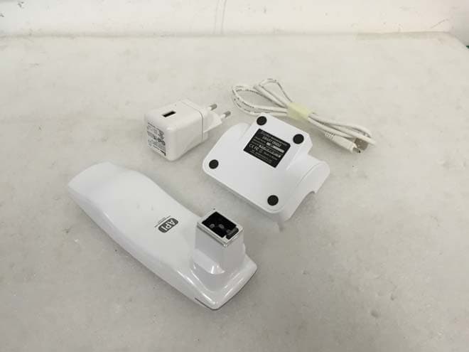
XYCAPI
Sep 10, 2015API
Equipment Class
DTS - Digital Transmission System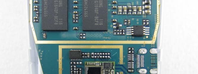
XYCAPSII
Jan 01, 2013PORTABLE SKIN/HAIR DIAGNOSIS SYSTEM
Equipment Class
DTS - Digital Transmission System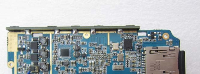
XYCASNII
Dec 27, 2012PORTABLE SKIN/HAIR DIAGNOSIS SYSTEM
Equipment Class
DSS - Part 15 Spread Spectrum Transmitter
XYCAPM
Sep 26, 2012ARAMO PROFESSIONAL MICROSCOPE
Equipment Class
DSS - Part 15 Spread Spectrum Transmitter