XZH-MC054V-RC-2DLighting Control Switch
ETi Solid State Lighting, Inc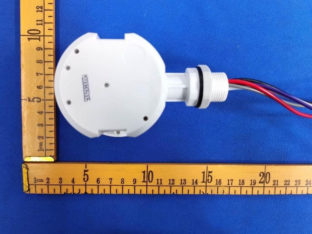
Click to zoom
Application Details
- Equipment Class
- DXX - Part 15 Low Power Communication Device Transmitter
- Date of Grant
- Mar 09, 2021
- Application Purpose
- Original Equipment
- Date of Application
- Mar 09, 2021
- Equipment Note
- Lighting Control Switch
- Frequency Range
- 5735.00000000 - 5855.00000000
- Country
- United States
Documents & Files
Document Text
Text extracted from the exhibit documents filed with the FCC. Open a document above to read the original.
Users Manual
Lighting Control Switch Version: A0 Page 1 of 11 Product Name: Lighting Control Switch Model No.: MC054V- RC- 2A MC054V- RC- 2B MC054V- RC- 2C MC054V- RC- 2D Issue Date: March 14, 2019 User Manual Lighting Control Switch Version: A0 Page 2 of 11 eatures1. Features 2.Parameter Input Operating Voltage Rage 108-305V AC, 50Hz/60Hz DC Input Voltage N/A Rated Voltage 120/277Vac,60Hz No-load Power N/A Stand-by Power <1W Surge Test L--N: 1kV Output Working Mode ON/OFF function, 1-10V step dimming Type of Load Inductive or resistive Load Load Capacity 120VAC: 4A; 277VAC: 3A Current of Load N/A Max. Surge Capacity 50A (50% Ipeak, twidth =500uS, 230Vac full load, cold start); 80A (50% Ipeak , twidth =200uS, 230Vac, full load, cold start) Dim Interface 1-10V Dimming < 50mA (Non-constant source) 10%(1.4-1.6V), 20%(1.9-2.1V), 30%(2.9-3.1V), 50% (4.9-5.1V) Synchronous Control N/A High Low-level N/A PWM Control N/A Sensor Parameters Operating Frequency 5.8 GHz ±75 MHz, ISM Band. Transmitting power 0.5mW Max. Operating voltage 120~277V AC, suitable to Euro & North American market. Patented microwave antenna, mounting height is 15m Max, suitable to install in most of warehouses. Supports high-sensitivity and low-sensitivity modes (for metal ceilings, metal reflector mounting environments) Work with 1-10V dimmable LED driver, easy to achieve 2-step or 3-step dimming function. New patented remote control to adjust the transmitting angle to avoid misuse. 5 years warranty Lighting Control Switch Version: A0 Page 3 of 11 Hold time 5s/30s/1min/3min/5min/10min/20min/30min Stand-by DIM Level 10%/20%/30%/50% Stand-by Period 0s/10s/1min/3min/5min/10min/30min/+∞ Detection Area 25%/50%/75%/100% 5lux/15lux/30lux/50lux/100lux/150lux/Disable (Ambient light diffusion) Detecting Radius See note 2 Mounting Height 15m Max Detecting Angle 150°(wall mounting), 360°(ceiling mounting) Wireless Module Operating Frequency N/A Transmitting power N/A Transmitting distance N/A Modulation mode N/A Number of coding N/A Operating Environment Operating Temperature -35 ...+55°C°C Storage Temperature Temperature:-40°C...+80°C;Humidity:10%-95% (non-condensing) Certificate Standards Safety standards IEC60669-2-1, IEC60669-1 AS/NZS 60669.1, AS/NZS 60669.2.1 UL60730-1 EMC standards EN55015, EN61000-3-2, EN61000-3-3, EN61547 AS/NZS CISPR 15, AS/NZS 4268 FCC Part 15C, Part 15B EN 60950-1, EN301489-1, EN 201489-3, EN300440 Environmental Requirem ent Compliant to RoHS Certificate cULus, CE, SAA, FCC, RED Others Wiring SJTW,5*18AWG (USA); H05RR-F,5*18AWG (Europe,Australi a); exposed line length: 810-830mm Wiring color Sheath: Black Core: Red,White,Black,Gray,Purple (US); blue, brown, red, purple,Gray (Europe, Australia) IP Rating IP65 Protection Class Class II Installation Independent Dimension (ΦxH)72*59mm Package Instruction+ White box+ White box tags+ Clapboard+ Carton(K=A) Net Weight MC054V RC A: 225g, MC054V RC B:246g, MC054V RC C:225g , MC054V RC D:165g Lifetime 5 years warranty @Ta 230V full load Lighting Control Switch Version: A0 Page 4 of 11 Note 1. “N/A”means not available. 2. Detection area is effected on volume of motion object and motion speed. The detection area is tested by a 165cm height person and walking speed is 0.5m/s. 1. Func tion 1) On/OFF Function ( stand-by period be set to “0”s) 2) 2-step dimming function (stand-by period be set to “+ ∞ ”) 3) 3-step dimming function (stand-by period be set to “10s/1min/3min/5min/10min/30min”) Lighting Control Switch Version: A0 Page 5 of 11 4.Dimension (mm) 1)MC054V- RC- 2 A,MC054V- RC- 2B, MC054V-RC- 2C Lighting Control Switch Version: A0 Page 6 of 11 2) MC054V- RC- 2D 5.Wiring (Europe,Australia version) (USA version) *The sensor is designed for connect one load only. Connect more than one loads may damage the sensor. Lighting Control Switch Version: A0 Page 7 of 11 6.Function Diagram 7.Radiation Pattern Ceiling mounting Ceiling mounted height: 3m Sensitivity: 100%/75%/50%/25% Ceiling mounted height: 6m Sensitivity: 100%/75%/50%/25% Ceiling mounted height: 9m Sensitivity: 100%/75%/50%/25% Ceiling mounted height: 12m Sensitivity: 100%/75%/50% Ceiling mounted height: 15m Sensitivity: 100%/75% Normal moving (Speed:1m/s) Normal moving (Speed:1m/s) Normal moving (Speed:1m/s) Normal moving (Speed:1m/s) Normal moving (Speed:1m/s) Lighting Control Switch Version: A0 Page 8 of 11 Slow moving (Speed 0.3m/s) Slow moving (Speed: 0.3m/s) Slow moving (Speed: 0.3m/s) Slow moving (Speed: 0.3m/s) Slow moving (Speed: 0.3m/s) *Only 100%/75%/50% detection sensitivity is workable when installed at 10m & 15m mounting height. 25% sensitivity is not able to detect motion signal. Wall mounting Horizon mounted height: 2m Sensitivity: 100%/75%/50%/25% Normal moving (Speed:1m/s) Slow moving (Speed 0.3m/s) Lighting Control Switch Version: A0 Page 9 of 11 8.Remote Control 9. Initialization 1/ On/Off function /3-step dimming function: After power on, the sensor automatically turns on light at 100% brightness. After 10sec, it turns off the light. During the initialization, the sensor is not able to detect movement. 2/ 2-step dimming function: After power on, the sensor automatically turns on light at 100% brightness. After 10sec, it dims the light to a low light level (set by stand-by dim level). During the initialization, the sensor is not able to detect movement. Lighting Control Switch Version: A0 Page 10 of 11 10. Factory Setting Detection area: 100%, Hold Time: 5S, Stand-by Period: 0s, Stand-by dim level: 10%, Daylight Sensor: Disable 11.Application Notice 1) The sensor should be installed by a professional electrician. Please turn off the power before installing, wiring, changing the setting of the DIP switch. 2) The sensor which installed in the plastic and glass lampshade will reduce the sensitivity.For every 3mm increase in thickness, the sensitivity will be reduced by 20%. 3) The dimming performance could be different from different 1-10v drivers. 4) The light sensitivity threshold is in a sunny e…
Text truncated - open the document above for the full version.
Attestation Statements
Date:2021.2.19 <Signature> Name: Sean Luo Title: Dept. Manager Applicant Company: ETI Solid State Lighting (Zhuhai) Ltd FCC ID : XZH-MC054V-RC-2D EUT Name : Lighting Control Switch Model No :MC054V-RC-2X, where “X=A to Z” All models are electrically identical , the only difference is way to install
Cover Letter(s)
DATE: 2021.2.19 Federal Communications Commission Authorization & Evaluation Division 7345 Oakland Mills Road Columbia, Maryland 21046 Authority to Act as Agent On our behalf, I appoint Dongguan New Testing Centre Co., Ltd;3F, No. 1 the 1st North Industry Road, Songshan Lake Science & Technology Park, Dongguan, Guangdong, China, 523808. to act as our agent in the preparation of this application for equipment certification. I certify that submitted documents properly describe the device or system for which equipment certification is sought. I also certify that each unit manufactured, imported or marketed, as defined in the Federal Communications Commission’s regulations will have affixed to it a label identical to that submitted for approval with this application. For instances where our authorized agent signs the application for certification on our behalf, I acknowledge that all responsibility for complying with the terms and conditions for certification, still resides with ETI Solid State Lighting (Zhuhai) Ltd; No.1, Zhongzhu Road South, Science & Technology Innovation Coast, High Tech District, Zhuhai City, Guangdong Prov., China <Signature> Name: Sean Luo Title: Dept. Manager Applicant Company: ETI Solid State Lighting (Zhuhai) Ltd
Cover Letter(s)
DATE : 2021.2.19 Equipment Autorisation Division Federal Communications Commission 7435 Oakland Mills Road Columbia, MD 21046 FCC ID: _ XZH-MC054V-RC-2D __ Product Name: _ Lighting Control Switch _____ Request for Confidentiality Pursuant to Sections 0.457 and 0.459 of the commission’s rules, we hereby request that the following documents be held confidential: (List here the documents for which you are seeking confidentiality – for example ...) Schematics Block diagram Operation description These materials contain trade secrets and proprietary information and are not customarily released to the public. The public disclosure of this information might be harmful to the company and provide unjustified benefits to our competitors. <Signature> Name: Sean Luo Title: Dept. Manager Applicant Company: ETI Solid State Lighting (Zhuhai) Ltd
External Photos
External photos Model: MC054V-RC-2D
ID Label/Location Info
Label and label location Model: MC054V-RC-2D
Internal Photos
Internal Photos Model: MC054V-RC-2D Antenna
RF Exposure Info
RFExposureevaluation Accordingto447498D01GeneralRFExposureGuidancev05 The1-gand10-gSARtestexclusionthresholdsfor100MHzto6GHzat testseparationdistances≤50mmaredeterminedby: [(max.powerofchannel,includingtune-uptolerance,mW)/(min.test separationdistance,mm)]·[√f(GHz)]≤3.0for1-gSARand≤7.5for 10-gextremitySAR,where f(GHz)istheRFchanneltransmitfrequencyinGHz PoweranddistanceareroundedtothenearestmWandmmbefore calculation Theresultisroundedtoonedecimalplaceforcomparison eirp=ptxgt=(EXd) 2 /30 where: pt=transmitteroutputpowerinwatts, gt=numericgainofthetransmittingantenna(unitless), E=electricfieldstrengthinV/m,---10 ((dBuV/m)/20) /10 6 d=measurementdistanceinmeters(m)---3m Sopt=(EXd) 2 /30xgt Antgain=0dBi;soAntnumericgain=1 Fieldstrength=78.51dBuV/m@3m SoPt={[10 (78.51/20) /10 6 x3] 2 /30x1}x1000mW=0.02mW So(0.02mW/5mm)x√5.855GHz=0.01<3 ThenSARevaluationisnotrequired
Test Report
TEST REPORT Report No. ...................................... : NTC-ER2101024 Applicant’s name ........................... : ETI Solid State Lighting (Zhuhai) Ltd Address .......................................... : No.1, Zhongzhu Road South, Science & Technology Innovation Coast, High Tech District, Zhuhai City, Guangdong Prov., China DONGGUAN NEW TESTING CENTRE CO., LTD ◎Address: 3F, No. 1 the 1st North Industry Road, Songshan Lake Science & Technology Park, Dongguan, Guangdong, China, 523808 Tel: +86-769-22212079 Web: http://www.ntc-cert.com E-mail: [email protected] Dongguan New Testing Centre Co., Ltd E-mail: [email protected] 3F, No. 1 the 1st North Industry Road, Songshan Lake Science & Technology Park, Dongguan, Guangdong, China, 523808 Page 1 of 30 Report No.: NTC-ER2101024 TABLE OF CONTENTS Test Report Declare ...................................................................................................................... 2 1. Summary of test results ........................................................................................................... 3 2. General test information .......................................................................................................... 3 2.1. Description of EUT ................................................................................................................... 3 2.2. Description of test modes ........................................................................................................ 4 2.3. Block diagram EUT configuration for test ............................................................................. 4 2.4. Test environment conditions ................................................................................................... 5 2.5. Measurement uncertainty ........................................................................................................ 5 3. Power Line Conducted Emission Test .......................................................................................... 6 3.1. Test equipment ........................................................................................................................... 6 3.2. Block diagram of test setup ......................................................................................................... 6 3.3. Power Line Conducted Emission Limits (Class B) ........................................................................ 6 3.4. Test Procedure ............................................................................................................................ 7 3.5. Test Result ................................................................................................................................... 7 4. Radiated emission test ........................................................................................................... 10 4.1. Test equipment ....................................................................................................................... 10 4.2. Block diagram of test setup ................................................................................................... 11 4.3. Limit .......................................................................................................................................... 13 4.4. Test Procedure ........................................................................................................................ 15 4.5. Test result ................................................................................................................................ 15 5. -20dB Bandwidth .................................................................................................................... 21 5.1. Test equipment ....................................................................................................................... 21 5.2. Block diagram of test setup ................................................................................................... 21 5.3. Limit .......................................................................................................................................... 21 5.4. Test Procedure ........................................................................................................................ 21 5.5. Test result ................................................................................................................................ 22 6. Antenna Requirements .......................................................................................................... 24 6.1. Limit .......................................................................................................................................... 24 6.2. Result........................................................................................................................................ 24 7. Test setup photograph ........................................................................................................... 25 7.1. Photos of radiated emission test .......................................................................................... 25 7.2. Photos of radiated emission test .......................................................................................... 25 8. Photos of the EUT .................................................................................................................. 27 Dongguan New Testing Centre Co., Ltd E-mail: [email protected] 3F, No. 1 the 1st North Industry Road, Songshan Lake Science & Technology Park, Dongguan, Guangdong, China, 523808 Page 2 of 30 Report No.: NTC-ER2101024 TEST REPORT DECLAREp Test Standard Used: FCC Rules and Regulations Part 15 Subpart C 15.249: 2019, ANSI C63.10:2013. We Declare: The equipment described above is tested by Dongguan New Testing Centre Co., Ltd and in the configuration tested the equipment complied with the standards specified above. The test results are contained i…
Text truncated - open the document above for the full version.
Test Setup Photos
Setup photos Model No: MC054V-RC-2D Conducted emission test Radiated emission test 30MHz – 1GHz Above 1GHz
Contact Information
Applicant
Sean Luo(Dept. Manager)
Test Firm
Dongguan New Testing Centre Co., LtdDave Gao
[email protected]86-15625558400
Technical Specifications
| # | Rule Parts | Frequency Range | Power Output |
|---|---|---|---|
| 1 | 15C | 5.74 GHz - 5.86 GHz | - |
Other Applications from ETi Solid State Lighting, Inc

XZH-K668-B-CW
Sep 16, 2026Remote control
Equipment Class
DSC - Part 15 Security/Remote Control Transmitter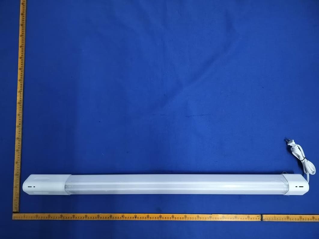
XZH-B02020601A
Jul 17, 2026Shoplight audio lighting
Equipment Class
DSS - Part 15 Spread Spectrum Transmitter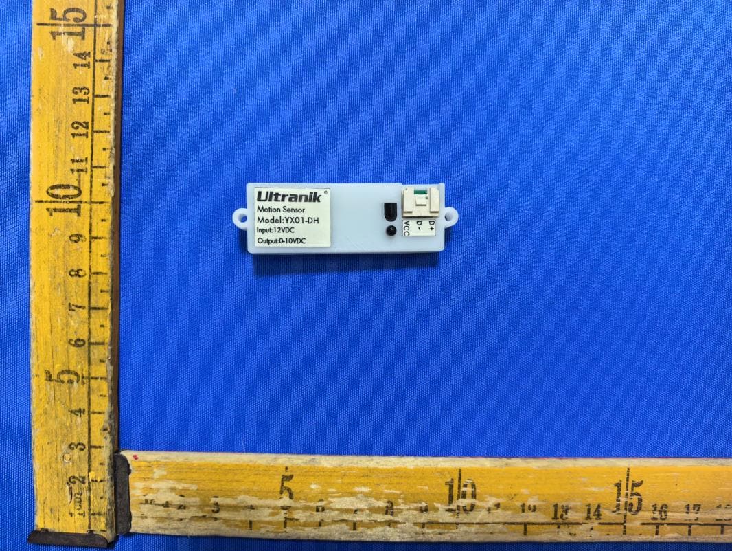
XZH-YX01-DH
Jul 14, 2026Motion Sensor
Equipment Class
DXX - Part 15 Low Power Communication Device Transmitter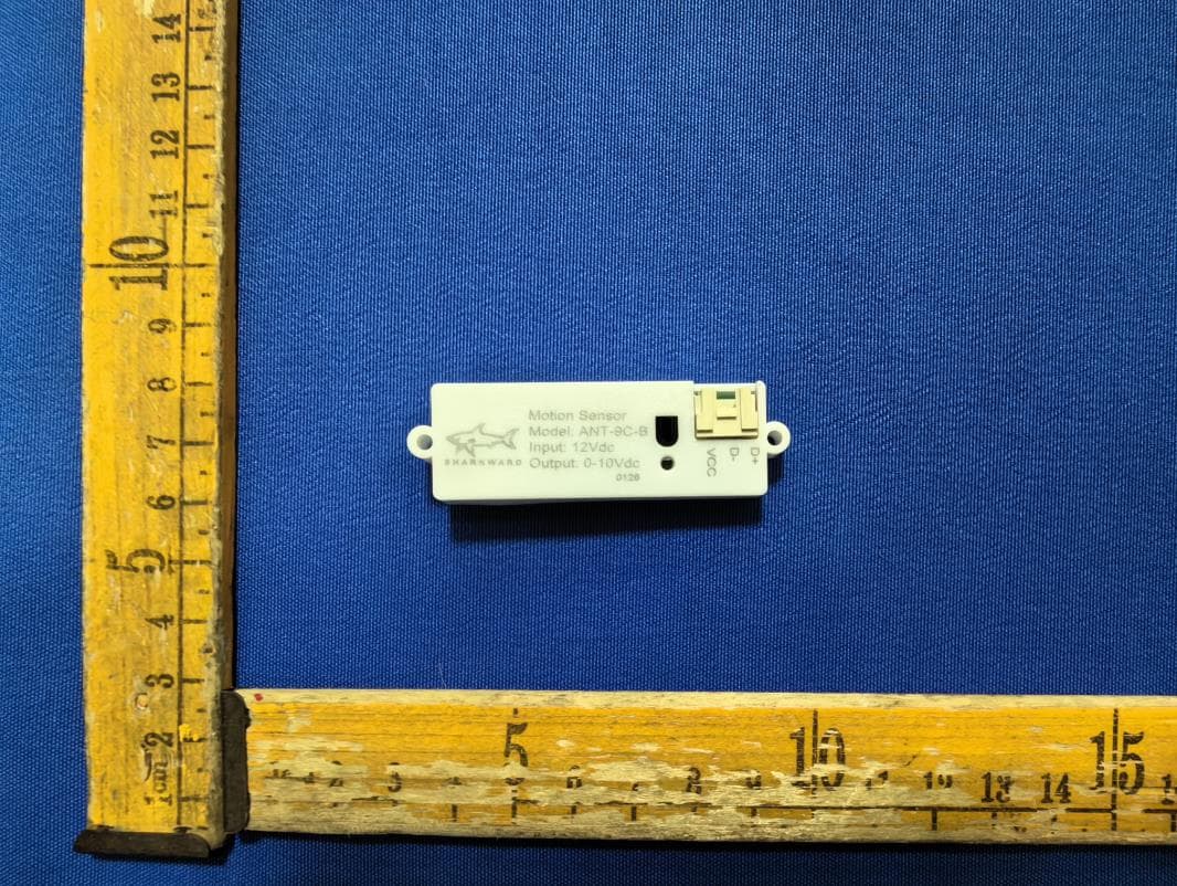
XZH-ANT-9C-B
Jul 14, 2026Motion Sensor
Equipment Class
DXX - Part 15 Low Power Communication Device Transmitter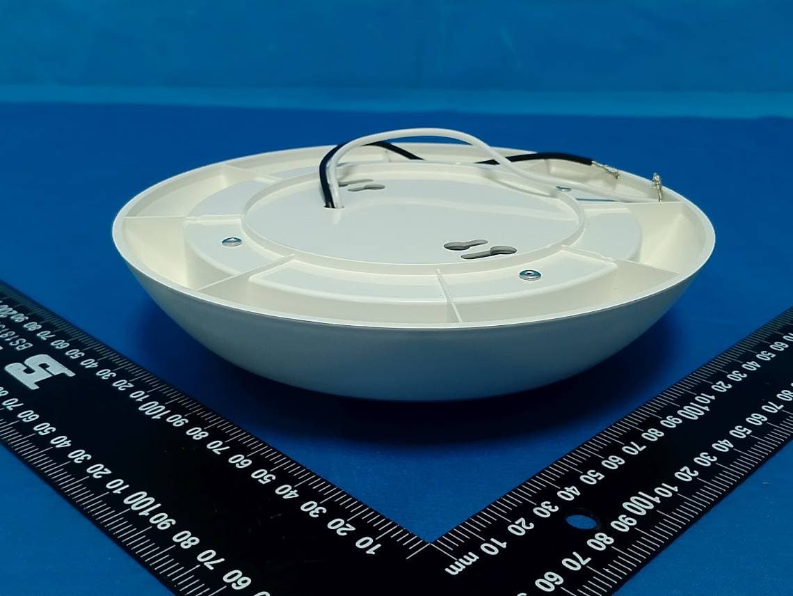
XZH-C012632026
May 25, 2026FLUSH MOUNT CEILING LIGHT WITH MOTION SENSOR
Equipment Class
DXX - Part 15 Low Power Communication Device Transmitter