Y2NRC189XHP-IPMA Wireless Communication Mesh Network in a Module
Radiocrafts AS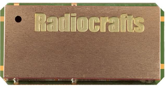
Click to zoom
Application Details
- Equipment Class
- DSS - Part 15 Spread Spectrum Transmitter
- Date of Grant
- Mar 27, 2023
- Application Purpose
- Original Equipment
- Date of Application
- Mar 27, 2023
- Equipment Note
- A Wireless Communication Mesh Network in a Module
- Frequency Range
- 903.00000000 - 927.00000000
- Company
- Radiocrafts AS
- Country
- Norway
Documents & Files
Document Text
Text extracted from the exhibit documents filed with the FCC. Open a document above to read the original.
Users Manual
Page 1 of 23 DATA SHEET RC18x2HP-IPM ©2022 Radiocrafts AS Data sheet RC18x2HP-IPM (rev. 1.6 ) 1 Product Description The RC18x2HP-IPM is a series of high power sub-1 GHz programmable ultra-low power module for RIIM (Radiocrafts Industrial IP Mesh). It is based on the open radio standard IEEE802.15.4 g/e, and implements IPv6 internet addressing with support for UDP, CoAP and encryption. The RC18x2HP-IPM is used to implement all the nodes in the network including leaf nodes, wireless router nodes and root-node/border routers. The module incudes ICI, the intelligent C-programmable I/O, along with all neccesary drivers and the operating system. ICI allows the user to program his own intelligent sensor/actuator inteface, or any other applciation with minimal effort. The programming capability of the module makes it possible to interface to any sensor/actuator or combination of sensors/actuators.Thereby, removing the need for an additional MCU to reduce overall cost and power consumption. 2 Applications • Coin cell battery systems • IIoT applications • Smart Sensor Technologies • Energy Management and Sustainability • Green House Monitoring and control • Elderly Care • Fire Detection • Home Security • Indoor Air Quality Monitoring • Industrial Temperature Control • Medical Climate Control • Predictive Maintenance • Tank Level/Flow Monitoring • Facilities and Infrastructure Management • Radiation and Leak Detection • Irrigation monitor and control 3 Features • Internet interoperability via IPv6 addressing, UDP packet transmission, DTLS encryption and CoAP protocol. • Multi-hop mesh technology. • Self building and self healing network. • Over The Air (OTA) updates • Very high node count mesh • Long RF range, several hundred meter LOS • Many electrical interfaces: 9 programmable GPIOs, I2C bus, SPI bus, UART and 2 ADC inputs • Intelligent C-Programmable I/O (ICI) easy to use C-based SDK to directly inteface any sensor/actuator • Ultra-low power for coin cell battery or energy harvesting • Pre-certified radio • Based on open radio standards IEEE 802.15.4 g/e • Frequency hopping via TSCH (6TiSCH) (Availeble for RIIM-SDK 1.20.0 and later) • Automatic acknowledge and retransmission Page 2 of 23 DATA SHEET RC18x2HP-IPM ©2022 Radiocrafts AS Data sheet RC18x2HP-IPM (rev. 1.6 ) 4 Quick Reference Data (typical at 3.6V, 868 MHz, 50 kb/s) Parameter RC1882HPCF-IPM RC1892HPCF-IPM Unit Frequency band 865-870 902-928 MHz Max output power 27 1 27 dBm Sensitivity (BER 1%) @50kb/s -111 -111 dBm Supply voltage 2.3 - 3.6 2.3 - 3.6 V Current consumption, RX/TX 12.5 / 350 12.5 / 350 mA Current consumption, Deep sleep 3.5 3.5 uA User application flash memory 32 32 kB User application RAM 8 8 kB Internal SPI Flash 1024 1024 kB Operating Temperature -30 to +85 -30 to +85 C 1 HW revision 1.00 is limited to 26 dBm, later revisions are 27 dBm. Page 3 of 23 DATA SHEET RC18x2HP-IPM ©2022 Radiocrafts AS Data sheet RC18x2HP-IPM (rev. 1.6 ) 5 RIIM overview The RIIM network consists of these key elements - The RIIM SDK o Software development kit with application frameworks and tools for creating and uploading end applications to the RC18x2HP-IPM - The IPM module o The IPM module can be configured as root, router or leaf node. ▪ As a root node it acts as the base of the mesh network. It can connect to an external network via ethernet or custom user application on other interfaces such as UART ▪ As a router node, it will be able to transport packets in the RIIM mesh network ▪ As a leaf node, it is not able to transport packets to other nodes except its parent. This mode uses the least amount of energy. o All modes supports customer ICI applications and external connections. Applications use the same RIIM Software Development Kit (SDK) for all node types. Below is an illustration of the different elements and the documentation available Figure 1. RIIM network – system and documentation overview Ethernet MAC/PHY SPI Ethernet RC1880-GPR RC18x2HP-IPM RC1880-GPR RC18x2HP-IPM RC1880-GPR RC18x2HP-IPM RC18x2HP-IPM Data sheet IPM SDK RIIM SDK User Manual RIIM SDK Quick Start Guide RIIM SDK API reference RC18x2HP-IPM Data sheet Sub 1 GHz IEEE 802.15.4g/e IPv6 UDP CoAP RC1880-GPR RC18x2HP-IPM Network: - Internet or local network RIIM User Manual Page 4 of 23 DATA SHEET RC18x2HP-IPM ©2022 Radiocrafts AS Data sheet RC18x2HP-IPM (rev. 1.6 ) 6 Firmware structure The RIIM module’s program memory is divided in 3 different segments. - The bootloader - The platform image - Application image Figure 2. System overview The bootloader is preloaded from Radiocrafts. It allows the user to upload new platform images or unique application images. The bootloader also allows the user to program unique encryption keys into the device. These keys are not possible to read out. The bootloader uses the standard UART port and operates at 115200 baud. Note that the bootloader also leaves all GPIO in tristate mode at power up. If a specific application requires controlled high or low level during start up, an external pull-up/pull-down is mandatory. The platform image is the main firmware part and includes the operating system, network stacks, drivers and application frameworks. The newest revision will be available from Radiocrafts SDK download as an encrypted image. When downloading a new platform image through the bootloader, the image will be decrypted internally in the module. The application code space has available 32 kB of flash space and 8 kB of RAM. MCU / Wireless Tranceiver (HW) Real Time Operating System (RTOS) Interface, system and module drivers Protocols: 802.15.4 g/e, CoAP IPv6, UDP, DTLS Application framework ICI application Bootstrap loader(BSL) Platform image Page 5 of 23 DATA SHEET RC18x2HP-IPM ©2022 Radiocrafts AS Data sheet RC18x2HP-IPM (rev. 1.6 ) 7 Software Development Kit (SDK) RC18x2HP-IPM allows each user to write his own application with minimal time and effort. This is accomplished through an SDK, which consists of 3 key blocks Figure 3. S…
Text truncated - open the document above for the full version.
Attestation Statements
Radiocrafts AS, Oslo Adresse/Address: Sandakerveien 64 NO-0484 OSLO NORWAY Nemko North America, Inc. 303 River Road Ottawa, Ontario, Canada K1V 1H2 Tel: (+47) 4000 5195 Fax: (+47) 22 71 29 15 Web: www.radiocrafts.com E-mail: [email protected] Foretaksnr./Enterprise No.: NO 985 876 096 MVA Deres ref. / Your ref. Vår ref. / Our ref. Tlf. direkte / Direct Line Date +47 4000 5195 Oslo, 2023-02-16 Covered Equipment Certification Attestation Letter ATTN.: Reviewing Engineer FCC ID: Y2NRC189XHP-IPM Radiocrafts (“the applicant”) certifies that the equipment for which authorization is sought is not “covered” equipment prohibited from receiving an equipment authorization pursuant to section 2.903 of the FCC rules. Note: If the equipment for which the applicant seeks authorization is produced by any of the entities identified on the current Covered List, the applicant should include an explanation on why the equipment is not “covered” equipment. Radiocrafts (“the applicant”) certifies that, as of the date of the filing of the application, the applicant is not identified on the Covered List as an entity producing “covered” equipment. Sincerely, _____________________ Ørjan Nottveit Radiocrafts AS 2023-02-16 Radiocrafts Embedded Wireless Solutions
Attestation Statements
Iailioc]afts Radiocrafts AS, Oslo Adresse/Address: Sandakerveien 64 NO-0484 OSLO NORWAY Tel: (+47) 4000 5195 Fax: (+47) 2271 29 15 Web: www.radiocrafts.com E-mail: [email protected] s.com Foretaksnr.,/Enterprise No. : NO 985 876 096 MVA ImDsddGd lilirelGss solutions 2t20t2023 U.S. Agent Designation for Service of Process - Certification Attestation Letter Nemko North America, lnc. 303 River Road Ottawa KMH2 Canada ATTN.: Reviewing Engineer FCC lD: Y2NRC1 89XHP-|PM Per section 2.911(d)(7) of the FCC rules, Radiocrafts AS ("the applicant") certifies that the equipment for which authorization is sought is designated to the following U.S. Designated agent* for service of process: Company Name: Schoenduve Corporation Physical U.S. company Address: 4010 Moorpark Ave #214 San Jose, cA95ll7 Agent name: Jim Schoenduve Agent Email Address: jim@schoenduve. com The above contact person accepts the obligation ior" service of process. The applicant accepts to maintain an agent for no less than one year after the grantee has terminated all marketing and importation or the conclusion of any Commission-related proceeding involving the equipment. Applicant Signed: Designated Agent Signed: (Required, if different to Appticant): f't ', , , lr', /i n, {' e,'^ / " / Signed: 1-i':'<z signed: /-ily'''-/-,- Printed name: @rjan Nottveit Printed nahe: James H. schoenduve Title: R&D Director Tiile: president company Name: Radiocrafts company Name: schoenduve corporation Date:212012023 Date: 3/1 0t2029 FRN:0033513482 * the applicant must designate a contact located in the United States for purposes of acting as the applicant's agent for service of process, regardless of whether the applicant is a domestic or foreign entity. An applicant located in the United States may designate itself as the agent for service of process.
Cover Letter(s)
Radiocrafts Embedded Wireless Solutions Radiocrafts AS, Oslo Adresse/Address: Sandakerveien 64 NO-0484 OSLO NORWAY Nemko North America, Inc. 303 River Road Ottawa, Ontario, Canada K1V 1H2 Tel: (+47) 4000 5195 Fax: (+47) 22 71 29 15 Web: www.radiocrafts.com E-mail: [email protected] Foretaksnr./Enterprise No.: NO 985 876 096 MVA Deres ref. / Your ref. Vår ref. / Our ref. Tlf. direkte / Direct Line Date +47 4000 5195 Oslo, 2022-11-02 AUTHORITY TO ACT AS AGENT - FCC On our behalf, I appoint Nemko North America, Inc. to act as our agent in the preparation of this application for equipment certification. I certify that submitted documents properly describe the device or system for which equipment certification is sought. I also certify that each unit manufactured, imported or marketed, as defined in FCC regulations will have affixed to it a label identical to that submitted for approval with this application. In signing this letter, Applicant certifies that neither the applicant nor any party to the application is not subject to a denial of Federal benefits, that include FCC benefits, pursuant to Section 5301 of the Anti-Drug Abuse Act of 1988, 21 U.S.C. § 862 because of a conviction for possession or distribution of a controlled substance. See 47 CFR 1.2002(b) for the definition of a "party" for these purposes. For instances where our authorized agent signs the application for certification on our behalf, I acknowledge that all responsibility for complying with the terms and conditions for certification, as specified by Nemko North America Inc., still resides still resides with us. . Sincerely, _____________________ Ørjan Nottveit
Cover Letter(s)
Radiocrafts Embedded Wireless Solutions Radiocrafts AS, Oslo Adresse/Address: Sandakerveien 64 NO-0484 OSLO NORWAY Attn: Reviewing Engineer Federal Communications Commission Tel: (+47) 4000 5195 Fax: (+47) 22 71 29 15 Web: www.radiocrafts.com E-mail: [email protected] Foretaksnr./Enterprise No.: NO 985 876 096 MVA Deres ref. / Your ref. Vår ref. / Our ref. Tlf. direkte / Direct Line Oslo, OSLO, 7 FEBRUARY 2023. To Whom It May Concern: Pursuant of Section 0.457 and 0.459 of the FCC Commission's Rules we hereby request confidentiality for documents given below. Letter cover FCC ID: Y2NRC189xHP-IPM Long term confidential: We request that the - Schematic diagrams - Part list /Bill of Material (BOM) - Block diagrams - Technical descriptions - Security acessment - Frequency hopping pattern description submitted with this application, are withheld from public review. The documents are company proprietary information that should never get into the possession of our competition. Short term confidential(180 days): We request that the - External Photos - Internal Photos - Datasheet/user manual submitted with this application, are withheld from public review in 180 days. The documents are company proprietary information that should never get into the possession of our competition. Please contact me if there is any information you may need. Sincerely, Radiocrafts Ørjan Nottveit
Cover Letter(s)
RC189XHP-IPM ©2022 Radiocrafts AS RC189XHP-IPM Model Differences Letter Page 1 of 1 Radiocrafts Embedded Wireless Solutions RC189xHP-IPM Model Differences Letter Oslo, 11/2/22 To whom it may concern: Radiocrafts hereby declares that the model RC189XHP-IPM is identical with the following products with the stated changes RC1892HPCF-IPM 352KB MCU FLASH, 1024KB SPI Flash, 88KB RAM RC1892HPC-IPM 352KB MCU FLASH, NO SPI Flash, 88KB RAM RC1893HPCF-IPM 352KB MCU FLASH, 1024KB SPI Flash, 40KB RAM RC1893HPC-IPM 352KB MCU FLASH, NO SPI Flash, 40KB RAM RC1894HPCF-IPM 704KB MCU FLASH, 2048KB SPI Flash, 152KB RAM RC1894HPC-IPM 704KB MCU FLASH, NO SPI Flash, 152KB RAM The only difference between the models are the internal ROM and RAM. The RF parameters and the interior structure are alike in these models.
External Photos
Radiocrafts Embedded Wireless Solutions RC189XHP-IPM ©2022 Radiocrafts AS RC189XHP-IPM Label Page 1 of 1 RC189XHP-IPM Label Location
RF Exposure Info
Prediction of MPE limit at a given distance Equation from page 18 of OET Bulletin 65, Edition 97-01 where:S = power density P = power input to the antenna G = power gain of the antenna in the direction of interest relative to an isotropic radiator R = distance to the center of radiation of the antenna Maximum peak output power at antenna input terminal:27,00(dBm) Maximum peak output power at antenna input terminal:501,1872336(mW) Antenna gain(typical):3(dBi) Maximum antenna gain:1,995262315(numeric) Prediction distance:20(cm) Prediction frequency:903(MHz) MPE limit for uncontrolled exposure at prediction frequency:0,6(mW/cm^2) Power density at prediction frequency:0,198944(mW/cm^2) Maximum allowable antenna gain:7,794211057(dBi) Margin of Compliance:4,794211057 2 4R PG S p =
Test Report
Report No. 481244-03-R01 Template version: C Nemko Group Nemko Scandinavia AS, Instituttveien 6, 2027 Kjeller, Norway TEL +47 22 96 03 30 EMAIL [email protected] nemko.com/no Test Report Product Radio module Name and address of the applicant Radiocrafts AS, attn Ø Nottveit Sandakerveien 64, N-0404 OSLO, Norway Name and address of the manufacturer Radiocrafts AS, attn Ø Nottveit Sandakerveien 64, N-0404 OSLO, Norway Model RC1892HP-CF Rating 3.6V DC (Primary Battery) Trademark - Serial number - Additional information 902-928 MHz band Tested according to FCC Part 15.247 Frequency Hopping Transmitters / Digital Transmission Systems Industry Canada RSS-247, Issue 2 Digital Transmission Systems (DTSs), Frequency Hopping Systems (FHSs) and Licence-Exempt Local Area Network (LE-LAN) Devices Order number 481244 Tested in period 2022-09-05 to 2022-12-12 Issue date 2023-02-03 Name and address of the testing laboratory Instituttveien 6 Kjeller, Norway www.nemko.com CAB Number: FCC: NO0001 ISED: NO0470 An accredited technical test executed under the Norwegian accreditation scheme Prepared by [Jan G Eriksen] Approved by [Frode Sveinsen] This report shall not be reproduced except in full without the written approval of Nemko. Opinions and interpretations expressed within this report are not part of the current accreditation. This report was originally distributed electronically with digital signatures. For more information contact Nemko. TEST REPORT FCC Part 15.247 Report no.: 481244-03-R01 FCC ID: Y2NRC189XHP-IPM Nemko Scandinavia AS Page 2 (33) Revision history Revision Date Comment Sign 00 2022-12-13 First edition JGER 01 2023-02-03 Editorials concerning duty cycle correction factor, Time of occupancy formula. JGER THIS TEST REPORT APPLIES ONLY TO THE ITEM(S) AND CONFIGURATIONS TESTED. Deviations from, additions to, or exclusions from the test specifications are described in “Summary of Test Data”. Nemko Group authorizes the above-named entity to reproduce this report provided it is reproduced in its entirety and for use by the entity’s employees only. Any reproduction of parts of this report requires approval in writing from Nemko Group. Any use that a third party makes of this report, or any reliance on or decisions to be made based on it, are the responsibility of such third parties. Nemko Group accepts no responsibility for damages suffered by any third party caused by decisions made or actions based on this report. TEST REPORT FCC Part 15.247 Report no.: 481244-03-R01 FCC ID: Y2NRC189XHP-IPM Nemko Scandinavia AS Page 3 (33) CONTENTS 1 INFORMATION ......................................................................................................................... 4 1.1 Test Item ................................................................................................................................................... 4 1.2 Normal test condition ................................................................................................................................. 5 1.3 Test Engineer(s) ........................................................................................................................................ 5 1.4 Antenna Requirement ................................................................................................................................ 5 1.5 EUT Operating Modes ............................................................................................................................... 5 1.6 Comments ................................................................................................................................................. 5 2 TEST REPORT SUMMARY ...................................................................................................... 6 2.1 General ..................................................................................................................................................... 6 2.2 Test Summary ........................................................................................................................................... 6 3 TEST RESULTS ........................................................................................................................ 7 3.1 Power Line Conducted Emissions ............................................................................................................. 7 3.2 20dB Bandwidth ........................................................................................................................................ 8 3.3 Pseudorandom Hopping Algorithm .......................................................................................................... 10 3.4 Hopping Bandwidth ................................................................................................................................. 11 3.5 Occupancy Time...................................................................................................................................... 13 3.6 Occupied Bandwidth (99% BW) ............................................................................................................... 15 3.7 Peak Power Output ................................................................................................................................. 17 3.8 Conducted Emissions at Antenna Connector ........................................................................................... 19 3.9 Restricted Bands of operation .................................................................................................................. 21 3.10 Radiated Emission, 30 – 1000 MHz ......................................................................................................... 22 3.11 Radiated Emissions, 1-10 GHz ................................................................................................................ 25 4 Measurement Uncertainty ...........................................................................…
Text truncated - open the document above for the full version.
Test Report
– 1 – Revised 12/9/13 Product Description CW Series ¼-wave antennas deliver outstanding performance in a rugged and cosmetically attractive package. These antennas are available with standard SMA or FCC Part 15 compliant RP-SMA connectors. RP-SMA connectors allow for easy field replacement while complying with FCC requirements. A wide variety of matching connectors permit numerous mounting options. Features • Low cost • Excellent performance • Omni-directional pattern • Wide bandwidth • Very low VSWR • Fully weatherized • Flexible main shaft • Rugged & damage-resistant • SMA or Part 15 compliant RP-SMA connector • Use with plastic* or metal enclosures *Requires proximity ground plane Electrical Specifications Center Frequency: 916MHz Recom. Freq. Range: 865–965MHz Wavelength: ¼-wave Peak Gain: 1.8dBi VSWR: <1.9 typ. at center Impedance: 50-ohms Connector: RP-SMA or SMA Oper. Temp. Range: –40°C to +90°C Electrical specifications and plots measured on 10.16 cm x 10.16 cm (4.00” x 4.00”) reference ground plane ANT-916-CW-QW Data Sheet by Ordering Information ANT-916-CW-QW (with RP-SMA connector) ANT-916-CW-QW-SMA (with SMA connector) 14.5 mm (0.57") 13.0 mm (0.51") 80.0 mm (3.15") 52.0 mm (2.05") 6.0 mm (0.24") 6.4 mm (0.25") End View 7.8 mm (0.31") 4.5 mm (0.18") – 2 – Counterpoise Quarter-wave or monopole antennas require an associated ground plane counterpoise for proper operation. The size and location of the ground plate relative to the antenna will affect the overall performance of the antenna in the final design. When used in conjunction with a ground plane smaller than that used to tune the antenna, the center frequency typically will shift higher in frequency and the bandwidth will decrease. The proximity of other circuit elements and packaging near the antenna will also affect the final performance. For further discussion and guidance on the importance of the ground plane counterpoise, please refer to Linx Application Note AN-00501: Understanding Antenna Specifications and Operation. by Data Sheet ANT-916-CW-QW VSWRReflected Power 3:1 2:1 1:1 25% 11% 0% 916MHz1016MHz816MHz 1.660 VSWR Graph What is VSWR? The Voltage Standing Wave Ratio (VSWR) is a measurement of how well an antenna is matched to a source impedance, typically 50-ohms. It is calculated by measuring the voltage wave that is headed toward the load versus the voltage wave that is reflected back from the load. A perfect match will have a VSWR of 1:1. The higher the first number, the worse the match, and the more inefficient the system. Since a perfect match cannot ever be obtained, some benchmark for performance needs to be set. In the case of antenna VSWR, this is usually 2:1. At this point, 88.9% of the energy sent to the antenna by the transmitter is radiated into free space and 11.1% is either reflected back into the source or lost as heat on the structure of the antenna. In the other direction, 88.9% of the energy recovered by the antenna is transferred into the receiver. As a side note, since the “:1” is always implied, many data sheets will remove it and just display the first number. How to Read a VSWR Graph VSWR is usually displayed graphically versus frequency. The lowest point on the graph is the antenna’s operational center frequency. In most cases, this will be different than the designed center frequency due to fabrication tolerances. The VSWR at that point denotes how close to 50-ohms the antenna gets. Linx specifies the recommended bandwidth as the range where the typical antenna VSWR is less than 2:1. 159 Ort Lane, Merlin, OR, US 97532 Phone: +1 541 471 6256 Fax: +1 541 471 6251 www.linxtechnologies.com
Test Setup Photos
TEST SET-UP PHOTOS Project no.: 481244 FCC ID: Y2NRC189XHP-IPM Page 1 (3) Radiated Emissions, 30 - 1000 MHz, as seen from EUT Radiated Emissions, 30 - 1000 MHz, as seen from antenna TEST SET-UP PHOTOS Project no.: 481244 FCC ID: Y2NRC189XHP-IPM Page 2 (3) Radiated Emissions, 1 GHz – 10 GHz, as seen from EUT Radiated Emissions, 1 GHz – 10 GHz, as seen from antenna TEST SET-UP PHOTOS Project no.: 481244 FCC ID: Y2NRC189XHP-IPM Page 3 (3) Power line Conducted Emissions Test
Contact Information
Applicant
Orjan Nottveit
Test Firm
Nemko Scandinavia ASFrode Sveinsen
[email protected]+4796905548
Technical Specifications
| # | Rule Parts | Frequency Range | Power Output |
|---|---|---|---|
| 1 | 15C | 903 MHz - 927 MHz | 500.00 mW |
Other Applications from Radiocrafts AS
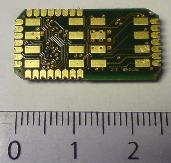
Y2NRC1290
Jun 28, 2011Low power wireless communication module
Equipment Class
DXX - Part 15 Low Power Communication Device Transmitter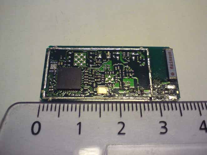
Y2NRC24XX
Apr 13, 2011Low power wireless communication module
Equipment Class
DTS - Digital Transmission System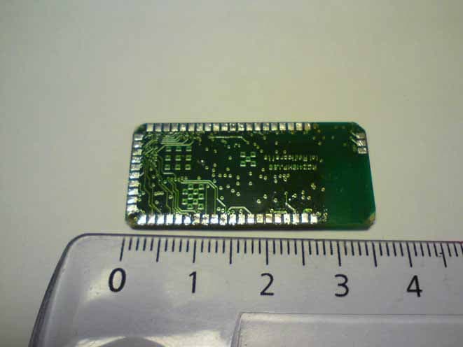
Y2NRC24XXHP
Apr 13, 2011Low power wireless communication module
Equipment Class
DTS - Digital Transmission System