Y47RN800B4A UMTS Femto Cell indoor base station to provide 3G voice and data service
SpiderCloud Wireless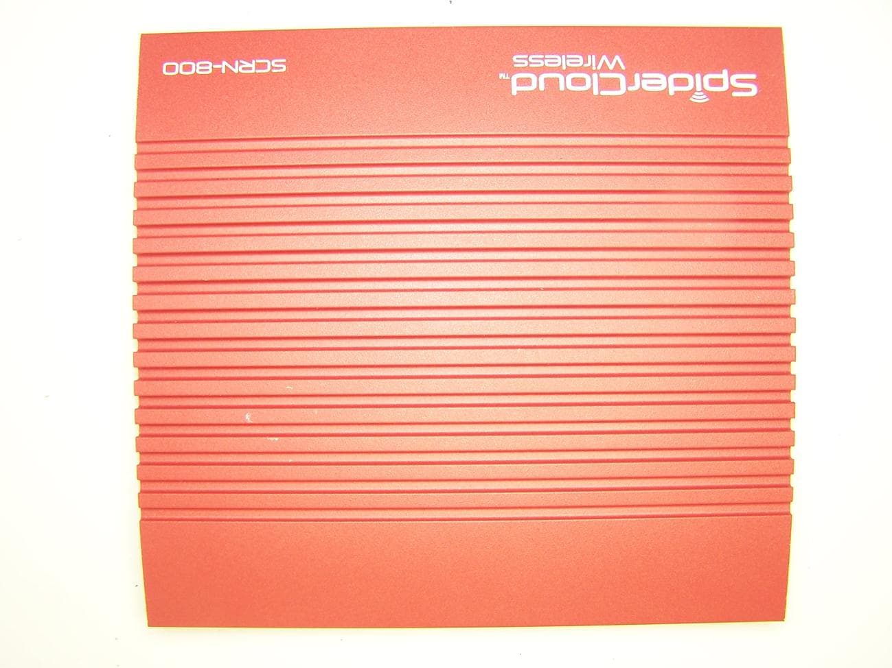
Click to zoom
Application Details
- Equipment Class
- TNB - Licensed Non-Broadcast Station Transmitter
- Date of Grant
- Feb 21, 2011
- Application Purpose
- Original Equipment
- Date of Application
- Feb 21, 2011
- Equipment Note
- A UMTS Femto Cell indoor base station to provide 3G voice and data service
- Frequency Range
- 2112.00000000 - 2153.00000000
- Company
- SpiderCloud Wireless
- Country
- United States
Documents & Files
Document Text
Text extracted from the exhibit documents filed with the FCC. Open a document above to read the original.
Users Manual
Hardware Installation Guide for SmartCloud® Radio Node - SCRN 800 Part number: DOC-RN-HW-02 Published: January 2011 © 2011 SpiderCloud Wireless, Inc. SpiderCloud and SmartCloud are registered trademarks of SpiderCloud Wireless, Inc. All Rights Reserved. FCC Statements Warning: In order to avoid the possibility of exceeding the FCC radio frequency exposure limits, the SCRN 800 must have a minimum distance of 20 cm from the body during normal operation. Changes or modifications not expressly approved by SpiderCloud Wireless engineering voids the user’s authority to operate the equipment. Note: This equipment has been tested and found to comply with the limits for a Class A digital device, pursuant to part 15 of the FCC Rules. These limits are designed to provide reasonable protection against harmful interference when the equipment is operated in a commercial environment. This equipment generates, uses, and can radiate radio frequency energy and, if not installed and used in accordance with the instruction manual, may cause harmful interference to radio communications. Operation of this equipment in a residential area is likely to cause harmful interference, in which case, the user will be required to correct the interference at his own expense. Industry Canada Statements This device has been designed to operate with the antenna listed below and having a maximum gain of 3 dB. Antennas not included in this list or having a gain greater than 3 dB are strictly prohibited for use with this device. The required antenna impedance is 50 ohms. •Laird MAF94307 •Larsen SPDA17806/2170 To reduce potential radio interference to other users, the antenna type and its gain should be so chosen that the equivalent isotropically radiated power (e.i.r.p.) is not more than permitted for successful communication. SpiderCloud Wireless 2500 Augustine Drive Suite 200 Santa Clara, CA 95054, USA http://www.spidercloud.com Tel: +1 408 567-9165 Email: [email protected] SpiderCloud Wireless, Inc. iii Contents System Overview . . . . . . . . . . . . . . . . . . . . . . . . . . . . . . . . . . . . . . . . . 1 Services Provided . . . . . . . . . . . . . . . . . . . . . . . . . . . . . . . . . . . . . . 2 SCRN System Isometric Front View and Rear View . . . . . . . . . . . 2 System Specifications. . . . . . . . . . . . . . . . . . . . . . . . . . . . . . . . . . . . . . 3 Frequency Bands of Operation . . . . . . . . . . . . . . . . . . . . . . . . . . . . 3 Size and Dimensions. . . . . . . . . . . . . . . . . . . . . . . . . . . . . . . . . . . . 4 Power . . . . . . . . . . . . . . . . . . . . . . . . . . . . . . . . . . . . . . . . . . . . . . . 4 Environmental Requirements . . . . . . . . . . . . . . . . . . . . . . . . . . . . . 4 Compliance . . . . . . . . . . . . . . . . . . . . . . . . . . . . . . . . . . . . . . . . . . . 4 Ports and LEDs. . . . . . . . . . . . . . . . . . . . . . . . . . . . . . . . . . . . . . . . . . . 5 Antennas. . . . . . . . . . . . . . . . . . . . . . . . . . . . . . . . . . . . . . . . . . . . . . . . 7 Installation and Mount Bracket Assembly . . . . . . . . . . . . . . . . . . . . . . . 8 Installation Procedure . . . . . . . . . . . . . . . . . . . . . . . . . . . . . . . . . . . 9 Detaching the SCRN from the Mount Bracket. . . . . . . . . . . . . . . . . 14 PoE+ . . . . . . . . . . . . . . . . . . . . . . . . . . . . . . . . . . . . . . . . . . . . . . . . . . . 15 Boot Sequence and SCSN Communication . . . . . . . . . . . . . . . . . . . . . 16 Related Documents . . . . . . . . . . . . . . . . . . . . . . . . . . . . . . . . . . . . . . . 17 Index . . . . . . . . . . . . . . . . . . . . . . . . . . . . . . . . . . . . . . . . . . . . . . . . . . . 19 SpiderCloud Wireless, Inc. Contents iv SpiderCloud Wireless, Inc. 1 System Overview The SmartCloud® Radio Node 800 (SCRN 800) is a low-cost, low-power (100mW) Node B designed for enterprises. The SCRN is 3GPP compliant, supporting Universal Mobile Telecommunications System (UMTS) Release 6 software and is upgradable to Release 7 and 8. The SCRN provides enterprises with dedicated high-quality, high-capacity UMTS coverage. The SCRN is easy to install and connects to the existing enterprise LAN using standard Ethernet cabling. The SCRN is managed by the SmartCloud® Services Node 8000 (SCSN 8000). Figure 1 SCRN Relationship to Enterprise and Carrier Core Networks LAN Intranet DMZ Enterprise Carrier Core DHCP EmailWeb Iu-CS, Iu-PS, Iuh Interfaces Iur Interface (between Controllers/RNCs) 3G Cipher Uu Int PoE+ Injector SCRN 800 Iu/Iuh Aggregator ACS IPSec Backhaul 1588 Iub Int RA DIO STAT US RAD IO ST AT U S RAD IO S T AT U S SwitchSwitch Firewall Security Gateway SCSN 8000 SCSN 8000 SpiderCloud Wireless, Inc. System Overview 2 Services Provided The SCRN provides the following services: •Complete enterprise mobility using licensed spectrum. •RF self-calibration for autonomous setup, operation, and management. •Enhanced networking. •Transparent integration into enterprise network environments. SCRN System Isometric Front View and Rear View The following diagrams display an isometric front view and rear view of the SCRN. Figure 2 Isometric Views with Mount-Bracket Assembly A N T B AN T A ETHE RNET CONSOL E AN T B R A DIO STAT US SpiderCloud Wireless SC RN 800 SpiderCloud Wireless, Inc. Hardware Installation Guide for SmartCloud® Radio Node - SCRN 800 3 Figure 3 Front View Figure 4 Rear View System Specifications Following are the system specifications for the SCRN frequency bands of operation, system size, power, environmental requirements, and compliance. Frequency Bands of Operation •Transmitter = 2110-2170MHz (Downlink). •Receiver = 1920-1980MHz (Uplink). •UMTS Band I monitor mode = 2110-2170MHz. •GSM low-band listen mode = 925-960MHz. •GSM high-band listen mode = 1805-1880MHz. RADIOSTATUS ANT B ANT A ETHERNETCONSOLE Link LED Activity LED SpiderCloud Wireless, Inc. System Specifications 4 Size and Dimensions •Height: — 3.81 centimeters (1.5 inch…
Text truncated - open the document above for the full version.
Cover Letter(s)
2500 Augustine Drive, Suite 200 Santa Clara, CA 95054 (408) 567-9165 Fax (408) 567-9498 December 22, 2010 MET Laboratories, Inc. 914 West Patapsco Avenue Baltimore, MD 21230 RE: CONFIDENTIALITY REQUEST FOR SCRN-800 FCC ID# Y47RN800B2 and ID # Y47RN800B4 To Whom It May Concern: This letter serves as an official request for confidentiality under sections 0.457 and 0.459 of CFR 47. We have requested that the items listed be permanently withheld from public view: Schematic Block diagram Internal Photos Parts List These items were required to be submitted with this application. This device is not a consumer product and is only serviceable by the Grantee or a sub-contractor with a non-disclosure agreement. The above documents are proprietary information that can never get into the possession of our competition. Please contact me if there is any information you may need. Sincerely, Don Sloan Director of Hardware Engineering SpiderCloud Wireless
External Photos
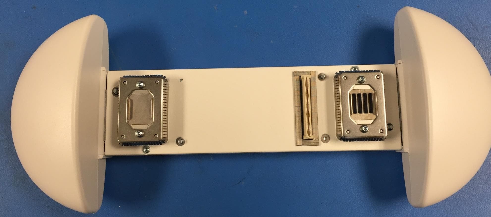
Photograph 1. bottom cover Photograph 2. EUT Photograph 3. external view of top cover
ID Label/Location Info
TÜVRheinland ® EN 60950-1 C US 2200 1 234 567 D C B AA B C D 765 432 1 MODIFICATIONS REVISIONDESCRIPTIONDATE © 2011 SPIDERCLOUD WIRELESS C SIZEDRAWING BY TITLE SPIDERCLOUD ENGINEER DATE DRAWING NUMBER TOLERANCES REV PROPRIETARY AND CONFIDENTIAL THE INFORMATION CONTAINED IN THIS DRAWING IS THE SOLE PROPERTY OF SPIDERCLOUD WIRELESS. ANY REPRODUCTION IN PART OR WHOLE WITHOUT THE WRITTEN PERMISSION OF SPIDERCLOUD WIRELESS IS PROHIBITED. ALL RIGHTS RESERVED 01120-01001 01/06/11 SEE NOTES TAC GRAPHICSDAN FARMER LABEL, AGENCY + RATINGS, SCRN-800, AP, BAND 4 Sheet 1 of 1 2500 Augustine Drive, #200 Santa Clara, CA 95054 NOTES: 1. ALL DIMENSIONS ARE IN INCHES. INTERPRET DIMENSIONS AND TOLERANCES PER ANSI Y14.5 1994. 2. TOLERANCES: DECIMALS .X = ± 0.05 .XX = ± 0.025 ANGLES = ± 0.5• 3. MATERIAL: .002” BRIGHT SILVER MYLAR WITH .001” MATTE LAMINATION. 4. ADHESIVE: CLEAR, PERMANENT, ACRYLIC ADHESIVE. 5. COLOR: BACKGROUND: SILVER. GRAPHICS: PMS BLACK. 5. LABEL MATERIAL, ADHESIVE AND PRINTING PROCESS TO CONFORM TO UL AND CSA STANDARDS FOR USE ON ABS PLASTIC AND METAL SURFACES. 6. VISUAL INSPECTION OF PART TO MEET CLASS A PER SPIDERCLOUD COSMETIC SPECIFICATION. 5. OUTLINES AND FEATURE LINES ARE FOR REFERENCE ONLY AND DO NOT PRINT. THIS FILE CONTAINS ARTWORK AND ART SPECIFICATIONS. 001PROTOTYPE DEVELOPMENT03/28/10 Label P/N: 01120-01 Model: SCRN-800 Input Rating: 41-57V 23W This class A digital apparatus complies with Canadian ICES-003. FCC ID: Y47RN800B4 IC: 9424A-RN800B4 Cet appareil numérique de la classe A est conforme à la norme NMB-003 du Canada. This device complies with part 15 of the FCC rules. Operation is subject to the following two conditions: (1) This device may not cause harmful interference, and (2) This device must accept any interference received, including interference that may cause undesired operation. Label P/N: 01120-01 Model: SCRN-800 Input Rating: 41-57V 23W This class A digital apparatus complies with Canadian ICES-003. FCC ID: Y47RN800B4 IC: 9424A-RN800B4 Cet appareil numérique de la classe A est conforme à la norme NMB-003 du Canada. This device complies with part 15 of the FCC rules. Operation is subject to the following two conditions: (1) This device may not cause harmful interference, and (2) This device must accept any interference received, including interference that may cause undesired operation. R 0.059 (4X) 3.00 1.50 200%
Operational Description
Theory of Operation The SCRN800 radio is a dual diversity receiver and single carrier WCDMA transmitter implemented with two commercially available transceiver ICs. The transceivers are located on a single small PCB with the digital baseband circuit on a separate access point PCB assembly. Page 3 of the radio schematic contains details of the transmitter and receiver frequencies. The A channel has an additional receive front-end that the B channel does not that is used to monitor the cellular down- link band. The transceiver: The receiver is based on direct conversion architecture. This architecture includes highly integrated wideband CDMA (WCDMA) receivers, reducing the bill of materials by fully integrating all interstage filtering. Inside the IC the front end includes three high performance, single-ended low noise amplifiers (LNAs), allowing the device to support tri-band receive (downlink monitoring). The integrated receive baseband filters offer selectable bandwidth, enabling the device to receive both WCDMA and GSM-EDGE radio signals. The selectable bandwidth filter, coupled with the multiband LNA input structure, allows GSM-EDGE signals to be monitored as part of a UMTS small base station. The transmitter uses a direct conversion modulator that achieves high modulation accuracy with low noise, eliminating the need for external transmit SAW filters. The power limiting and control function is done by creating a calibration table in the manufacturing process and using the programmable output power features of the transceiver. The fully integrated phase lock loops (PLLs) provide high performance and low power fractional-N frequency synthesis for both receive and transmitter sections. Precautions were taken in the IC to provide the isolation demanded by frequency division duplex (FDD) systems. All VCO and loop filter components are fully integrated. The transceiver contains a low noise variable gain direct conversion transmitter architecture that removes the need for external transmit SAW filters however the duplexer utilized provides a bandpass transfer function response. The direct conversion architecture significantly reduces the risk of transmit harmonics across all bands due to the simplified nature of the frequency plan. Each of the 2 receivers digital interface is connected to its own A/D. I/Q Modulator The I/Q modulator converts the transmit baseband input signals to RF. Calibration techniques are used to maintain accurate IQ balance and phase across frequency and environmental conditions, thus ensuring that 3GPP carrier leakage and EVM and ACLR requirements are met under all conditions, thus providing the modulation limiting function. The on-chip calibrations are carried out during the transmit PLL lock time and are self-contained inside the transceiver IC. PLL (frequency stabilization circuitry) All necessary components are fully integrated for both transmit and receive synthesizers, including loop filters, VCOs, and tank components. The VCOs run at 2× the high band frequency and 4× the low band frequency. The dividers are external to the synthesizer loop. This minimizes VCO leakage power at the desired frequency and tuning range requirements of the VCO. The VCOs use a multiband structure to cover the wide frequency range required. The IC design incorporates both frequency and amplitude calibration to ensure that the oscillator is always operating with its optimum performance. The charge pump and loop filter are internally trimmed in the transceiver IC’s manufacture to remove variations associated with manufacture and frequency. The transceiver requires a 26 MHz reference frequency input. A voltage controlled temperature compensated crystal oscillator (VCTCXO) is used to provide the 100ppb reference. The 26 MHz reference is buffered inside the IC and distributed to the respective blocks, such as the synthesizer PFD inputs. The transceiver provides two buffered outputs: a buffered version of the 26 MHz reference on Pin REFCLK and a 19.2 MHz WCDMA chip clock on Pin CHIPCLK. The 19.2 MHz chip clock is a multiple of the 3.84 MHz chip rate used in WCDMA. The chip clock is generated by an integrated PLL and contains no IC external settings. Transmitter Output Circuit The transceiver IC transmit output is followed by a driver and power amplifier, a directional coupler, an isolator, a duplexer, and an RF switch. The isolator is used to provide an optimum termination for the power amplifier. Each component was selected for linearity. The duplexer has a bandpass response in both paths. PLL reference FREQUENCY CHARACTERISTICS Line Parameter Test Condition Max. Units 2.1 frequency 26.000 MHz 2.2 Initial frequency tolerance Frequency offset at 25°C, sixty minutes after reflow over a 10% range of supply voltage ±2 ppm 2.3 Temperature rate of change Maximum rate of change of temperature condition for guaranteed stability specifications 1 °C/min 2.4 In-service short term frequency stability (Note 1) Over any 24 hours 50°C ~ 70°C at fixed supply voltage and load 0°C ~ 70°C ±100ppB 0°C ~ 85°C ±250ppB ±80 ppb 2.6 Frequency variation with supply voltage ±2% variation in supply voltage at 25°C ±10 ppb 2.7 Frequency variation with load ±2% variation in magnitude from 10pF ±5 ppb Duplexer A duplexer is installed after the antenna switch and has 2 outputs. The outputs of the duplexer connect to the transmitter output and the primary receiver input LNA. Each path through the duplexer has a bandpass transfer function. The bandpass action attenuates undesired out of band signals providing suppression of spurious radiation. Isolator The transmit path contains an isolator to improve the load seen by the final amplifier stage improving the amplifiers linearity. The isolator and final amplifier are band specific. Antenna Frequency Range: 824-894 MHz, 880-960 MHz, 1575 MHz, 1710-1880 MHz, 1850-1995 MHz, 1920- 2170 MHz, 2400-2500 MHz Gain 1 - 3 dBi VSWR <2.5:1 Polarization Linear Azimuth (3dB beamwidth) Omni…
Text truncated - open the document above for the full version.
RF Exposure Info
Innovative Technology for a Connected World Heptaband TM External Wireless Antennas global solutions: local support TM USA: +1.800.323.3757 Europe: +46.8.555.722.00 Asia: +886.2.2286.2828 www.lairdtech.com FEaTurEs • Operates simultaneously in more than seven frequency bands supporting - Cellular, Quadband GSM+UMTS/3G, GPS, AWS, WIFI, WLAN, and WISP • Available in knuckle swivel snap or SMA/TNC/RPTNC connector options. • Blade style external antenna measures only 6.33” MarkETs • Wireless terminal • Point-of-Sale • Machine to machine • Automatic meter reading • Home security HEpTaband TM ExTErnal wirElEss anTEnna oFFErs ulTiMaTE bandwidTH wiTH ovEr sEvEn FrEquEncy rangEs Laird Technologies Heptaband portable wireless antennas provide excellent radio transmission characteristics while offering the ultra flexibility of seven bands in one profile. With operating frequencies of 824 - 894 MHz, 880 - 960 MHz, 1575 MHz, 1710 - 1880MHz, 1850 - 1990 MHz, 1920 - 2170 MHz, and 2400 - 2500 MHz, the antenna is the ideal choice when multiple bandwidths are required in various regional and global applications. Additionally, the blade style antenna features both knuckle and swivel snap-in or SMA/TNC/RPTNC connector options. Innovative Technology for a Connected World Heptaband TM External Wireless Antennas ANT-DS-HepTAbAND 0609 Any information furnished by Laird Technologies, Inc. and its agents is believed to be accurate and reliable. Responsibility for the use and application of Laird Technologies materials rests with the end user, since Laird Technologies and its agents cannot be aware of all potential uses. Laird Technologies makes no warranties as to the fitness, merchantability or suitability of any Laird Technologies materials or products for any specific or general uses. Laird Technologies shall not be liable for incidental or consequential damages of any kind. All Laird Technologies products are sold pursuant to the Laird Technologies’ Terms and Conditions of sale in effect from time to time, a copy of which will be furnished upon request. © Copyright 2009 Laird Technologies, Inc. All Rights Reserved. Laird, Laird Technologies, the Laird Technologies Logo, and other marks are trade marks or registered trade marks of Laird Technologies, Inc. or an affiliate company thereof. Other product or service names may be the property of third parties. Nothing herein provides a license under any Laird Technologies or any third party intellectual property rights. Typical aziMuTH paTTErnTypical ElEvaTion paTTErn spEciFicaTions ELECTRICAL Frequency Range: 824-894 MHz, 880-960 MHz, 1575 MHz, 1710-1880 MHz, 1850-1990 MHz, 1920-2170 MHz, 2400-2500 MHz Gain 1 - 3 dBi VSWR <2.5:1 Polarization Linear Azimuth (3dB beamwidth) Omnidirectional Impedance 50 Ω Temperature Range-5° C to +50° C Power 10 W Mounting Style Snap-in/Captive, SMA, RPSMA, TNC, RPTNC Dimensions (mm) 6.3" x .36" (161 x 9.3) with knuckle angle MODEL NUMBER PART NUMBERMOUNTING STyLECOLOR HEPTA-SM MAF94300SMABlack HEPTA-RSM MAF94301RP-SMABlack HEPTA-TN-G MAF94302TNCGray HEPTA-RTN MAF94303RP-TNCBlack HEPTA-IP04 MAF94304SNAPIN/CAPTIVE, 100mm of RG178 coax with I-PEX connectorBlack HEPTA-MMCX04 MAF94305SNAPIN/CAPTIVE, 100mm of RG178 coax MMCX connectorBlack HEPTA-FL04 MAF94306SNAPIN/CAPTIVE, 100mm of RG178 coax flying leadBlack HEPTA-TN MAF94307TNCBlack HEPTA90-TN MAF94309TNC, Blade Angle - 90 degreeBlack
RF Exposure Info
2500 Augustine Drive, Suite 200 Santa Clara, CA 95054 (408) 567-9165 Fax (408) 567-9498 RF Exposure Statement: 1. Limits established from FCC 1.10310, 2.1092, 2.1093 Table 1—Limits for Maximum Permissible Exposure (MPE) Frequency range (MHz) Electric field strength (V/m) Magnetic field strength (A/m) Power density (mW/cm 2 ) Averaging time (minutes) (A) Limits for Occupational/Controlled Exposures 0.3–3.0 614 1.63 *(100) 6 3.0–30 1842/f 4.89/f *(900/f 2 ) 6 30–300 61.4 0.163 1.0 6 300–1500 f/300 6 1500–100,000 5 6 (B) Limits for General Population/Uncontrolled Exposure 0.3–1.34 614 1.63 *(100) 30 1.34–30 824/f 2.19/f *(180/f 2 ) 30 30–300 27.5 0.073 0.2 30 300–1500 f/1500 30 1500–100,000 1.0 30 f = frequency in MHz * = Plane-wave equivalent power density Note 1 to Table 1: Occupational/controlled limits apply in situations in which persons are exposed as a consequence of their employment provided those persons are fully aware of the potential for exposure and can exercise control over their exposure. Limits for occupational/controlled exposure also apply in situations when an individual is transient through a location where occupational/controlled limits apply provided he or she is made aware of the potential for exposure. Note 2 to Table 1: General population/uncontrolled exposures apply in situations in which the general public may be exposed, or in which persons that are exposed as a consequence of their employment may not be fully aware of the potential for exposure or can not exercise control over their exposure. 2. Maximum Exposure Prediction (From page 19 of OET 65) Where: D in cm P in mW R in cm And Gain numeric for 3 dB is 2 S power density is in 3. Results The Band IV limit is 1.41 calculated from CFAR 47 Section 1.1310 table 1. S the power density at 20 cm is: S= 0.008 for Band IV which is below the uncontrolled exposure limit for UMTS band IV. The following note will be added to the installation manual. Warning: In order to avoid the possibility of exceeding the FCC radio frequency exposure limits, the SCRN800 must have a minimum distance of 20 cm from the body during normal operation. 4. References 2.1091 (c) Mobile devices that operate in the Cellular Radiotelephone Service, the Personal Communications Services, the Satellite Communications Services, the General Wireless Communications Service, the Wireless Communications Service, the Maritime Services and the Specialized Mobile Radio Service authorized under subpart H of part 22 of this chapter, parts 24, 25, 26 and 27 of this chapter, part 80 of this chapter (ship earth stations devices only) and part 90 of this chapter are subject to routine environmental evaluation for RF exposure prior to equipment authorization or use if they operate at frequencies of 1.5 GHz or below and their effective radiated power (ERP) is 1.5 watts or more, or if they operate at frequencies above 1.5 GHz and their ERP is 3 watts or more. Unlicensed personal communications service devices, unlicensed millimeter wave devices and unlicensed NII devices authorized under §§15.253, 15.255, and 15.257, and subparts D and E of part 15 of this chapter are also subject to routine environmental evaluation for RF exposure prior to equipment authorization or use if their ERP is 3 watts or more or if they meet the definition of a portable device as specified in §2.1093(b) requiring evaluation under the provisions of that section. All other mobile and unlicensed transmitting devices are categorically excluded from routine environmental evaluation for RF exposure prior to equipment authorization or use, except as specified in §§1.1307(c) and 1.1307(d) of this chapter. Applications for equipment authorization of mobile and unlicensed transmitting devices subject to routine environmental evaluation must contain a statement confirming compliance with the limits specified in paragraph (d) of this section as part of their application. Technical information showing the basis for this statement must be submitted to the Commission upon request. (4) In some cases, e.g., modular or desktop transmitters, the potential conditions of use of a device may not allow easy classification of that device as either mobile or portable (also see §2.1093). In such cases, applicants are responsible for determining minimum distances for compliance for the intended use and installation of the device based on evaluation of either specific absorption rate (SAR), field strength or power density, whichever is most appropriate. 2.1093 (c) Portable devices that operate in the Cellular Radiotelephone Service, the Personal Communications Service (PCS), the Satellite Communications Services, the General Wireless Communications Service, the Wireless Communications Service, the Maritime Services, the Specialized Mobile Radio Service, the 4.9 GHz Band Service, the Wireless Medical Telemetry Service (WMTS) and the Medical Device Radiocommunication Service (MedRadio), authorized under subpart H of part 22 of this chapter, parts 24, 25, 26, 27, 80 and 90 of this chapter, subparts H and I of part 95 of this chapter, and unlicensed personal communication service, unlicensed NII devices and millimeter wave devices authorized under subparts D and E, 15.253, 15.255 and 15.257 of this chapter are subject to routine environmental evaluation for RF exposure prior to equipment authorization or use. All other portable transmitting devices are categorically excluded from routine environmental evaluation for RF exposure prior to equipment authorization or use, except as specified in 1.1307(c) and 1.1307(d) of this chapter. Applications for equipment authorization of portable transmitting devices subject to routine environmental evaluation must contain a statement confirming compliance with the limits specified in paragraph (d) of this section as part of their application. Technical information showing the basis for this statement must be submitted to the Commission upon request. (3) Compliance with SAR limits can …
Text truncated - open the document above for the full version.
Test Report
MET Laboratories, Inc. Safety Certification - EMI - Telecom Environmental Simulation 914 WEST PATAPSCO AVENUE ! BALTIMORE, MARYLAND 21230-3432 ! PHONE (410) 354-3300 ! FAX (410) 354-3313 33439 WESTERN AVENUE ● UNION CITY, CALIFORNIA 94587 ● PHONE (510) 489-6300 ● FAX (510) 489-6372 3162 BELICK STREET ● SANTA CLARA, CALIFORNIA 95054 ● PHONE (408 748-3585 ● FAX (510) 489-6372 The Nation’s First Licensed Nationally Recognized Testing Laboratory February 11, 2011 Spider Cloud Wireless 231 Springside Drive, Suite 201 Akron, OH 44333 Dear Jerry Shore, Enclosed is the EMC Wireless test report for compliance testing of the Spider Cloud Wireless, SCRN800 as tested to the requirements of the FCC Certification rules under Title 47 of the CFR Part 27 Subpart L and RSS- 139, Issue 2, February 2009 for Broadband Radio Service (BRS) Devices. Thank you for using the services of MET Laboratories, Inc. If you have any questions regarding these results or if MET can be of further service to you, please contact me. Sincerely yours, MET LABORATORIES, INC. Jennifer Warnell Documentation Department Reference: (\Spider Cloud Wireless\EMC30395-FCC27 Rev. 1) Certificates and reports shall not be reproduced except in full, without the written permission of MET Laboratories, Inc. MET Laboratories, Inc. Safety Certification - EMI - Telecom Environmental Simulation 914 WEST PATAPSCO AVENUE ! BALTIMORE, MARYLAND 21230-3432 ! PHONE (410) 354-3300 ! FAX (410) 354-3313 33439 WESTERN AVENUE ● UNION CITY, CALIFORNIA 94587 ● PHONE (510) 489-6300 ● FAX (510) 489-6372 3162 BELICK STREET ● SANTA CLARA, CALIFORNIA 95054 ● PHONE (408 748-3585 ● FAX (510) 489-6372 MET Report: EMC30395-FCC27 Rev. 1 © 2011, MET Laboratories, Inc. Page ii of vii Electromagnetic Compatibility Criteria Test Report for the Spider Cloud Wireless Model SCRN800 Tested under FCC Certification Rules Title 47 of the CFR, Part 27 Subpart L & RSS-139, Issue 2, February 2009 MET Report: EMC30395-FCC27 Rev. 1 February 11, 2011 Prepared For: Spider Cloud Wireless 231 Springside Drive, Suite 201 Akron, OH 44333 Prepared By: MET Laboratories, Inc. 914 W. Patapsco Ave Baltimore, MD 21230 Electromagnetic Compatibility Spider Cloud Wireless Cover Page SCRN800 CFR Title 47 Part 15B & Part 27; ICES-003 & RSS-139 MET Report: EMC30395-FCC27 Rev. 1 © 2011, MET Laboratories, Inc. Page iii of xviii Electromagnetic Compatibility Criteria Test Report for the Spider Cloud Wireless Model SCRN800 Tested Under FCC Certification Rules Title 47 of the CFR, Part 27 Subpart L & RSS-139, Issue 2, February 2009 Manasi Bhandiwad, Project Engineer Jennifer Warnell Electromagnetic Compatibility Lab Documentation Department Engineering Statement: The measurements shown in this report were made in accordance with the procedures indicated, and the emissions from this equipment were found to be within the limits applicable. I assume full responsibility for the accuracy and completeness of these measurements, and for the qualifications of all persons taking them. It is further stated that upon the basis of the measurements made, the equipment tested is capable of operation in accordance with the requirements of Part 27 M of the FCC Rules and Industry Canada standard RSS-139, Issue 2, February 2009 under normal use and maintenance. Shawn McMillen, Wireless Manager Electromagnetic Compatibility Lab Electromagnetic Compatibility Spider Cloud Wireless Report Status SCRN800 CFR Title 47 Part 15B & Part 27; ICES-003 & RSS-139 MET Report: EMC30395-FCC27 Rev. 1 © 2011, MET Laboratories, Inc. Page iv of xviii Report Status Sheet Revision Report Date Reason for Revision February 11, 2011 Initial Issue. Electromagnetic Compatibility Spider Cloud Wireless Table of Contents SCRN800 CFR Title 47 Part 15B & Part 27; ICES-003 & RSS-139 MET Report: EMC30395-FCC27 Rev. 1 © 2011, MET Laboratories, Inc. Page v of ix Table of Contents I. Executive Summary ................................................................................................................................................. 1 A. Purpose of Test ................................................................................................................................................... 2 B. Executive Summary ............................................................................................................................................ 2 II. Equipment Configuration ....................................................................................................................................... 3 A. Overview ............................................................................................................................................................. 4 B. References ........................................................................................................................................................... 5 C. Test Site .............................................................................................................................................................. 5 D. Description of Test Sample ......................................................................................…
Text truncated - open the document above for the full version.
Contact Information
Applicant
Timothy Lam(Sr. QA Manager)
Technical Contact
SpiderCloud WirelessDon Sloan
[email protected]330-665-7637
231 Springside Drive · Akron · United States
Test Firm
MET Laboratories, Inc.John Mason
Technical Specifications
| # | Rule Parts | Frequency Range | Power Output | Emission | Tolerance |
|---|---|---|---|---|---|
| 1 | 27 | 2.11 GHz - 2.15 GHz | 111.00 mW | 4M24F9W | 1.0000000000 ppm |
Other Applications from SpiderCloud Wireless
Y478818C24
Nov 23, 2015Universal Small Cell 8818 LTE/LTE Module
Equipment Class
PCB - PCS Licensed Transmitter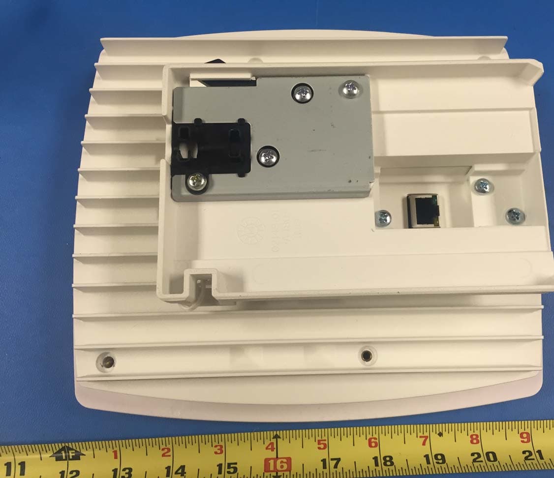
Y47RN310B4B2E
Oct 08, 2015SpiderCloud Radio Node
Equipment Class
PCB - PCS Licensed Transmitter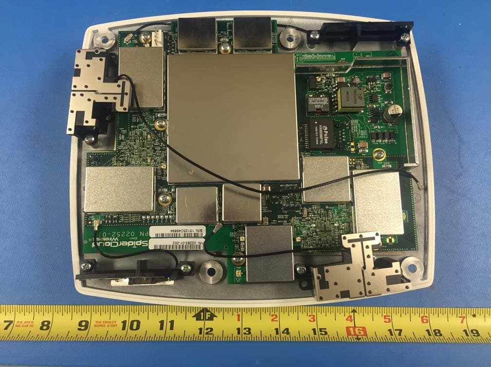
Y47RN310B4B13E
Oct 08, 2015SpiderCloud Radio Node
Equipment Class
TNB - Licensed Non-Broadcast Station Transmitter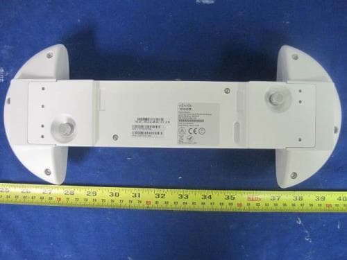
Y478718M24
May 14, 2015Universal Small Cell 8718
Equipment Class
PCB - PCS Licensed TransmitterY47RN310B7B2
Dec 21, 2014SpiderCloud Radio Node
Equipment Class
PCB - PCS Licensed Transmitter