Y4N70055RDigital Video Baby Monitor
Mobi Technologies, Inc.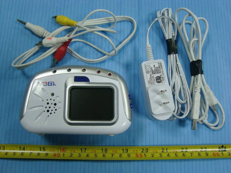
Click to zoom
Application Details
- Equipment Class
- DSS - Part 15 Spread Spectrum Transmitter
- Date of Grant
- Feb 20, 2011
- Application Purpose
- Original Equipment
- Date of Application
- Feb 20, 2011
- Equipment Note
- Digital Video Baby Monitor
- Frequency Range
- 2410.87500000 - 2471.62500000
- Company
- Mobi Technologies, Inc.
- Country
- United States
Documents & Files
Document Text
Text extracted from the exhibit documents filed with the FCC. Open a document above to read the original.
Users Manual
Compatible with... Wireless Audio/Video Monitoring System Compatible with... Compatible with... TABLE OF CONTENTS Introduction1 Package Contents2 Features3 Consumer Guide to Product Safety 4-5 Knowing your Receiver6 Knowing Your Camera7 Installation & Setup8 Monitor Operation9-10 Camera Operation11 Audio/Video & USB Operation12 Troubleshooting13 Radio Interference Advice14 Warranty15 Notes16 INTRODUCTION Congratulations on the purchase of the MobiCam Digital DL Monitoring Sys- tem, which brings you the latest in wireless technology. We are sure that you will be pleased with the quality and features of this product but recommend that you read these instructions carefully before use in order to fully benefit from its many features. The MobiCam Digital DL enables you to transmit picture and sound wirelessly, which is ideal for many situations such as monitoring a baby, young children, pets, or elderly. Additionally it can also be used for household security or as an office or warehouse surveillance system. Your MobiCam DL uses digital transmission to ensure a clear and consistent picture. The signal also passes easily through interior walls. However, buildings with metal frames or placing the camera near large metal objects may cause signal degradation. If reception is poor, moving the camera or receiver may fix this problem. 1 PACKAGE CONTENTSFEATURES 1 x Receiver Unit 1 x Camera Unit (#70056, additional cameras sold separately) 1 X Receiver Power Cord 1 X Camera Power Cord 1 x AV cable 1 set of mounting screws and anchors NOTE: If you find any of the contents are missing or should you need to order replace- ment parts, please contact the manufacturer or visit www.getmobi.com. 2 FEATURES • 2.4” Color High Resolution TFT LCD Display • Voice Activated Picture & Sound with Auto Mute • Audio Only Mode • No installation needed—ready to use • Compact design for easy portability • Transmission range up to 300 ft. • Powerful Night Vision with 20 ft. range • Extra Wide Camera Viewing Angle • Expandable up to 4 Cameras with automatic camera scanning option • Camera operates on AC or 4 AA Alkaline Batteries (not included). • Monitor operates on AC or 5 Alkaline AA Batteries (not included) • Optional rechargeable battery pack is available (item # 70077). • USB Output for PC connection • Use as a wireless webcam 3 CONSUMER GUIDE TO PRODUCT SAFETY Please read this instruction manual before using your MobiCam Digital DL sys- tem. When using electrical appliances, basic safety precautions should always be followed. Please keep safe for future reference. • This product is not intended to be used as a medical monitor and its use should not replace adult supervision. • Periodically examine this product for damage to the cord, housing or other parts that may result in the risk of fire, electric shock or injury. Do not operate any product with a damaged cord or plug. If the Color Wireless Monitor malfunctions or is damaged in any manner please contact the manufacturer for examination and repair to avoid a hazard. • Never use transmitter and receiver near water (i.e. bathtub, sink, etc.). • The AC adaptors are not Toys. 4 • Always use transmitter and receiver where there is adequate ventilation. To prevent overheating, keep away from heat sources such as radiators, heat registers, stoves, or other appliances that produce heat. • Use only a dry cotton cloth to keep the Camera and Monitor units free of dust. Do no use a dampened cloth, water, or liquid cleaner of any kind. • Remove the battery from the Monitor during long periods of non- use as alkaline batteries can leak. • Unplug the AC adaptors from the Monitor and Camera during peri ods of non-use. To disconnect from the power supply, grip the transformer and pull from the power socket. Never pull by the cord. • Replace battery with the same equivalent type. Please dispose of old, defective batteries in an environmentally friendly manner in accordance with the relevant legislation. • Only use the Monitoring System with the supplied power adaptors. 5 KNOWING YOUR RECEIVER 1. TFT LCD Display 2. Control (+) (-) 3. Mode Button 4. Power indicator 5. Sound Bar LEDs 6. Speaker 7. Volume and power On/Off switch 8. Mini USB Output 9. DC Jack 10. A/V Jack 6 KNOWING YOUR CAMERA 11. Camera Lens 12. Power indicator 13. Mic 14. Night Vision Sensor 15. Link Button 16. Power On / Off 17. DC Jack 7 INSTALLATION & SETUP The MobiCam Digital DL Monitor is designed to be powered by either batteries or the AC/DC adaptors. You can also purchase a rechargeable battery pack (item # 70077) available at getmobi.com or retailer to use with your monitor. Using AC/DC adaptor: • Plug the connector of the AC adaptor into the DC Jack on the unit (fig. 9 & 17). • Plug the power cord into an outlet. • Switch the power plug to the ON position (fig. 7 & 16) • The power indicator lights will illuminate once the units are turned on (fig. 4 & 12) Using Batteries: • Remove the battery door at the bottom/back of each unit by loosening the child-safe screw and sliding the cover downward to release. • Both units can use 1.5 volt AA size batteries. (Always use batteries of the same brand and age, alkaline batteries are recommended) Insert 4 AA batteries into camera and 5 AA batteries into the monitor. • Replace the covers by aligning the tabs with the tab holes and tighten ing the child-safe screws. Please note that the life of batteries is limited. Therefore, when monitoring over long periods and, in particular, overnight, it is recommended to use AC adaptors for both the camera and the monitor unit. Warning: 1. Do not mix old and new batteries. 2. Do not mix alkaline, standard or rechargeable batteries 3. Remove the batteries during long periods of non-use. 4. Use only the AC adaptors supplied with the package. Optional Battery Pack: The Monitor on your system has a built-in battery recharging circuit. Make sure you only use the optional battery pack (Item # 70077), as standard rechargeable batteries …
Text truncated - open the document above for the full version.
Cover Letter(s)
a nic FCC Confidential Authorization Date: 201 1-01-14 FEDERAL COMMUNICATIONS COMMISSIONS Authorization and Evaluation Division 7435 Oakland Mills Road Columbia, MD 21046 Confidentiality Request regarding application for certification of FCC ID: Y4N70055R Pursuant to Sections 0.457 and 0.459 of the Commission’s Rules, we hereby request confidential treatment of information accompanying this application as outlined below: • Detailed Circuit Schematics ofEUT--- (Long term) • Block Diagram--- (Long term) • Circuit Description--- (Long term) The above materials contain trade secrets and proprietary information not customarily released to the public. The public disclosure of these materials may beharmful to the applicant and provide unjustified benefits to itscompetitors. The applicant understands that pursuant to Section 0.457 ofthe Rules, disclosure of this application and all accompanying documentation will not bemade before the date of the Grant for this application. Title: President Company Name: Mobi Technologies, Inc. David Naghi MOB! TeclinoIoies, Inc.4 5913 Blackwelder Street + Culver City, CA90232 • Tel.424.672,6600 Fax:424.672.6628
External Photos
EXHIBIT B - EUT EXTERNAL PHOTOGRAPHS EUT – Full View EUT – Front View EUT – Rear View EUT – Side View 1 EUT – Side View 2 EUT – Bottom View EUT – Adapter View
ID Label/Location Info
EXHIBIT A - FCC ID LABELING AND LOCATION FCC ID Label FCC ID Label Location Label here The label shown shall be permanently affixed at a conspicuous location on the device and be readily visible to the user at the time purchase (Labeling requirements per 2.925)
Internal Photos
EXHIBIT C - EUT INTERNAL PHOTOGRAPHS EUT – Battery Cover off View EUT – Cover off View EUT – Main Board Top View EUT – Main Board Bottom View EUT – Main Board without RF Module Bottom View EUT – RF Board Top Shielding off View EUT – RF Board Bottom View Antenna EUT – LCD Display Top View EUT – LCD Display Bottom View
RF Exposure Info
Note: This test report is prepared for the customer shown above and for the device described herein. It may not be duplicated or used in part without prior written consent from Bay Area Compliance Laboratories Corp. This report must not be used by the customer to claim product certification, approval, or endorsement by NVLAP*, NIST, or any agency of the Federal Government. * This report may contain data that are not covered by the NVLAP accreditation and are marked with an asterisk “*" (Rev.2) SAR EVALUATION REPORT For Mobi Technologies Inc. 5913 Blackwelder Street, Culver City, CA 90232, USA FCC ID: Y4N70055R Report Type: Original Report Product Type: Digital Video Baby Monitor Test Engineer: Quinn Jiang Report Number: R1101043-SAR Report Date: 2011-02-16 Reviewed By: Victor Zhang RF Lead Prepared By: (18) Bay Area Compliance Laboratories Corp. 1274 Anvilwood Avenue, Sunnyvale, CA 94089, USA Tel: (408) 732-9162 Fax: (408) 732 9164 Mobi Technologies Inc. FCC ID: Y4N70055R Report Number: R1101043-SAR SAR Evaluation Report Page 2 of 56 Summary of Test Results Rule Part(s): FCC §2.1093, IEEE 1528 Test Procedure(s): FCC OET Bulletin 65-C; IEEE 1528 Device Category: Exposure Category: Portable Device General Population/Uncontrolled Exposure Device Type: Digital Video Baby Monitor Modulation Type: GFSK TX Frequency Range: 2410.875-2471.625 MHz (19 Channels) Maximum Conducted Power Tested: 15.65 dBm Antenna Type(s) Tested: Internal Antenna, Gain: 1.6 dBi Body-Worn Accessories: Belt Clip Face-Head Accessories: None Battery Type (s) Tested: 6 VDC Max. SAR Level (s) Measured: 0.019 W/Kg, 1g Body Tissue Mobi Technologies Inc. FCC ID: Y4N70055R Report Number: R1101043-SAR SAR Evaluation Report Page 3 of 56 TABLE OF CONTENTS 1 GENERAL DESCRIPTION ................................................................................................................................5 1.1 PRODUCT DESCRIPTION FOR EQUIPMENT UNDER TEST (EUT) .......................................................................5 1.2 EUT TECHNICAL SPECIFICATION....................................................................................................................5 2 TEST FACILITY..................................................................................................................................................6 3 REFERENCE, STANDARDS AND GUILDELINES .......................................................................................7 3.1 SAR LIMITS....................................................................................................................................................8 4 DESCRIPTION OF TEST SYSTEM..................................................................................................................9 4.1 IEEE SCC-34/SC-2 P1528 RECOMMENDED TISSUE DIELECTRIC PARAMETERS...........................................10 4.2 MEASUREMENT SYSTEM DIAGRAM..............................................................................................................11 4.3 SYSTEM COMPONENTS..................................................................................................................................12 4.4 DASY4 MEASUREMENT SERVER..................................................................................................................12 4.5 DATA ACQUISITION ELECTRONICS...............................................................................................................13 4.6 PROBES.........................................................................................................................................................13 4.7 ET3DV6 PROBE SPECIFICATION...................................................................................................................13 4.8 E-FIELD PROBE CALIBRATION PROCESS.......................................................................................................14 4.9 DATA EVALUATION......................................................................................................................................14 4.10 LIGHT BEAM UNIT........................................................................................................................................16 4.11 MEDIUM........................................................................................................................................................16 4.12 SAM TWIN PHANTOM..................................................................................................................................17 4.13 DEVICE HOLDER FOR SAM TWIN PHANTOM................................................................................................17 4.14 SYSTEM VALIDATION KITS...........................................................................................................................18 4.15 ROBOT..........................................................................................................................................................19 5 EQUIPMENT LIST AND CALIBRATION.....................................................................................................20 5.1 EQUIPMENTS LIST & CALIBRATION INFO......................................................................................................20 6 SAR MEASUREMENT SYSTEM VERIFICATION .....................................................................................21 6.1 SYSTEM ACCURACY VERIFICATION..............................................................................................................21 6.2 IEEE P1528 RECOMMENDED REFERENCE VALUE FOR HEAD.........................................................................21 6.3 SYSTEM SETUP BLOCK DIAGRAM.................................................................................................................21 7 EUT TEST STRATEGY AND METHODOLOGY.........................................................................................22 7.1 TEST POSITIONS FOR DEVICE…
Text truncated - open the document above for the full version.
Test Report
Note: This test report is prepared for the customer shown above and for the device described herein. It may not be duplicated or used in part without prior written consent from Bay Area Compliance Laboratories Corp. This report must not be used by the customer to claim product certification, approval, or endorsement by NVLAP*, NIST, or any agency of the Federal Government. * This report contains data that are not covered by the NVLAP accreditation and are marked with an asterisk “★” (Rev.2) FCC PART 15.247 MEASUREMENT AND TEST REPORT For Mobi Technologies, Inc. 5913 Blackwelder Street, Culver City, CA 90232, USA FCC ID: Y4N70055R Report Type: Original Report Product Type: Digital Video Baby Monitor Test Engineer: Alvin Huang Report Number: RSZ10122418 Report Date: 2011-02-18 Reviewed By: Merry Zhao EMC Engineer Prepared By: Bay Area Compliance Laboratories Corp. (Shenzhen) 6/F, the 3rd Phase of WanLi Industrial Building, ShiHua Road, FuTian Free Trade Zone Shenzhen, Guangdong, China Tel: +86-755-33320018 Fax: +86-755-33320008 Mobi Technologies, Inc. FCC ID: Y4N70055R Report No.: RSZ10122418 Page 2 of 36 FCC Part15.247 Test Report TABLE OF CONTENTS GENERAL INFORMATION.......................................................................................................................................4 PRODUCT DESCRIPTION FOR EQUIPMENT UNDER TEST (EUT) .....................................................................................4 OBJECTIVE...................................................................................................................................................................4 RELATED SUBMITTAL(S)/GRANT(S).............................................................................................................................4 TEST METHODOLOGY..................................................................................................................................................4 TEST FACILITY.............................................................................................................................................................4 SYSTEM TEST CONFIGURATION ..........................................................................................................................6 DESCRIPTION OF TEST CONFIGURATION......................................................................................................................6 EQUIPMENT MODIFICATIONS.......................................................................................................................................6 EUT EXERCISE SOFTWARE..........................................................................................................................................6 EXTERNAL I/O CABLE..................................................................................................................................................6 BLOCK DIAGRAM OF TEST SETUP................................................................................................................................6 SUMMARY OF TEST RESULTS ...............................................................................................................................7 FCC §15.247 (i) & §2.1093- RF EXPOSURE.................................................................................................................8 APPLICABLE STANDARDS.............................................................................................................................................8 TEST RESULT...............................................................................................................................................................8 FCC §15.203 – ANTENNA REQUIREMENT ............................................................................................................9 APPLICABLE STANDARD..............................................................................................................................................9 ANTENNA CONNECTOR CONSTRUCTION......................................................................................................................9 FCC §15.207(a) – AC LINE CONDUCTED EMISSIONS ......................................................................................10 APPLICABLE STANDARD............................................................................................................................................10 MEASUREMENT UNCERTAINTY..................................................................................................................................10 EUT SETUP................................................................................................................................................................10 EMI TEST RECEIVER SETUP.......................................................................................................................................11 TEST EQUIPMENT LIST AND DETAILS.........................................................................................................................11 TEST PROCEDURE......................................................................................................................................................11 TEST RESULTS SUMMARY..........................................................................................................................................11 TEST DATA................................................................................................................................................................11 FCC §15.205, §15.209 & §15.247(d) – RADIATED SPURIOUS EMISSIONS......................................................14 APPLICABLE STANDARD............................................................................................................................................14 MEASUREMENT UNCERTAINTY....................................................................................…
Text truncated - open the document above for the full version.
Test Setup Photos
EXHIBIT D - TEST SETUP PHOTOGRAPHS AC Line Conducted Emissions - Front View AC Line Conducted Emissions - Side View Below 1 GHz: Radiated Emissions - Front View Below 1 GHz: Radiated Emissions - Rear View Above 1 GHz: Radiated Emissions - Front View Above 1 GHz: Radiated Emissions - Rear View
Contact Information
Applicant
David Naghi(President)
Test Firm
Bay Area Compliance Laboratory Corp. (Shenzhen)John Chan
Technical Specifications
| # | Rule Parts | Frequency Range | Power Output |
|---|---|---|---|
| 1 | 15C | 2.41 GHz - 2.47 GHz | 36.73 mW |
Other Applications from Mobi Technologies, Inc.
Y4N-IBO
Apr 21, 2015IBO Bluetooth speaker
Equipment Class
DSS - Part 15 Spread Spectrum Transmitter
Y4N70208R
Feb 10, 2013MobiCam DXR Touch Wireless Monitoring System
Equipment Class
DSS - Part 15 Spread Spectrum Transmitter
Y4N70209T
Feb 10, 2013MobiCam DXR Touch Wireless Monitoring System
Equipment Class
DSS - Part 15 Spread Spectrum Transmitter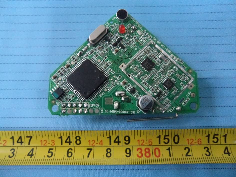
Y4N-70290T
Jan 12, 2012Pure Sounds Wireless Audio Monitor (Transmitter Unit)
Equipment Class
DSS - Part 15 Spread Spectrum Transmitter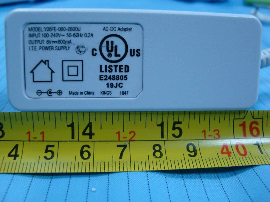
Y4N70055T
Feb 20, 2011Digital Video Baby Monitor
Equipment Class
DSS - Part 15 Spread Spectrum Transmitter