YHEMASM-02199LE Bluetooth Module
Ablelink Electronics Limited
Click to zoom
Application Details
- Equipment Class
- DSS - Part 15 Spread Spectrum Transmitter
- Date of Grant
- Aug 24, 2014
- Application Purpose
- Original Equipment
- Date of Application
- Aug 21, 2014
- Equipment Note
- LE Bluetooth Module
- Frequency Range
- 2402.00000000 - 2480.00000000
- Company
- Ablelink Electronics Limited
- Country
- Hong Kong
Documents & Files
Document Text
Text extracted from the exhibit documents filed with the FCC. Open a document above to read the original.
Users Manual
Griffin Bluetooth Module: MASM-02199 Integrators Guide Griffin Technology 2030 Lindell Avenue Nashville, Tennessee 37203 USA 615-399-7000 griffintechnology.com This component has been granted modular approval by the FCC and Industry Canada. The module may not be modified from it’s original design, including but not limited to component changes, Shield Changes, Antenna Changes, or PCB layout changes. The device should only be connected in your device using the provided connection points on the module. The Host product also has specific labeling requirements in English and French 1.Host product must have “Contains FCC ID: YHEMASM-02199“ and “Contains IC: 6384A-MASM02199“ and "Contenir IC: 6384A-MASM02199" 2. Host product manual must have the following statements (for this particular case): a. FCC and IC two part statements (can be combined). b. Modifications not approved by Griffin could void the user’s authority to operate the device c. IC s tatement concerning using the correct antenna: radio transmitter may only operate using an antenna of a type and maximum (or lesser) gain approved for this transmitter by Industry Canada. To reduce potential radio interference to other users, the antenna type and its gain should be so chosen that the equivalent isotropically radiated power (e.i.r.p.) is not more than necessary for successful communication.” A French language version of this must also be provided. RSS-GEN, Section 7.1.3 – “This device complies with Industry Canada licensed-exempt RSS standard(s). Operation is subject to the following two conditions: (1) this device may not cause interference, and (2) this device must accept any interference, including interference that may cause undesired operation of the device.” And: RSS-GEN, Section 7.1.3 - «Ce dispositif est conforme à la norme Industrie Canada RSS licence exempté (s). Son fonctionnement est soumis aux deux conditions suivantes: (1) cet appareil ne peut pas provoquer d'interférences, et (2) cet appareil doit accepter toute interférence, y compris les interférences qui peuvent causer un mauvais fonctionnement de l'appareil. And: FCC 15.19(a)(3) – “This device complies with Part 15 of the FCC Rules. Operation is subject to the following two conditions: (1) this device may not cause interference, and (2) this device must accept any interference, including interference that may cause undesired operation of the device.”
Attestation Statements
8/13/2014 National Technical Systems – Silicon Valley TCB 41039 Boyce Road Fremont, CA 94538 FCC ID: YHEMASM-02199 Dear Examiner: I am writing to attest that the Griffin BC5 Bluetooth (FCCID: YHEMASM-02199) has not changed or been modified since the testing occurred in July of 2013. Sincerely, Arthury Chau President
Cover Letter(s)
National Technical Systems – Silicon Valley TCB 41039 Boyce Road Fremont, CA. 94538 RE: FCC ID: YHEMASM-02199 To whom it may concern: The enclosed documents constitute a formal submittal and application for Equipment Authorization for a Bluetooth Low Energy module pursuant to the following rules: Subpart C of Part 15 of FCC Rules (CFR 47), Intentional Radiators National Technical Systems – Silicon Valley, as duly authorized agent prepared this submittal. A copy of the letter of our appointment as agent is included with the application. If there are any questions or if further information is needed, please contact National Technical Systems – Silicon Valley for assistance. Sincerely, Mark Hill Staff Engineer Page 1 of 1
Cover Letter(s)
Request for Confidentiality 28 th May 2014 Subject: Confidentiality Request for: YHEMASM-02199 Pursuant to FCC 47 CRF 0.457(d) and 0.459 and/or RSP-100, the applicant requests that a part of the subject FCC and/or IC application be held confidential. Type of Confidentiality Requested Exhibit Short Term Permanent Block Diagrams Short Term External Photos Short Term Permanent* 1 Internal Photos Short Term Permanent Operation Description/Theory of Operation Short Term Permanent Parts List & Placement/BOM Short Term Permanent Tune-Up Procedure Short Term Permanent Schematics Short Term Test Setup Photos Short Term Permanent* User’s Manual *Note: _____ AbleLink Electronics LTD. has spent substantial effort in developing this product and it is one of the first of its kind in industry. Having the subject information easily available to "competition" would negate the advantage they have achieved by developing this product. Not protecting the details of the design will result in financial hardship. Permanent Confidentiality: The applicant requests the exhibits listed above as permanently confidential be permanently withheld from public review due to materials that contain trade secrets and proprietary information not customarily released to the public. Short-Term Confidentiality: The applicant requests the exhibits selected above as short term confidential be withheld from public view for a period of ___(180)___ days from the date of the Grant of Equipment Authorization and prior to marketing. This is to avoid premature release of sensitive information prior to marketing or release of the product to the public. Applicant is also aware that they are responsible to notify FCC in the event information regarding the product or the product is made available to the public. FCC will then release the documents listed above for public disclosure pursuant to FCC Public Notice DA 04-1705. The applicant understands that until such time that Industry Canada distinguishes between Short Term and Permanent Confidentiality, either type of marked exhibit above will simply be marked Confidential when submitted to IC. Sincerely, By: _____President__ __Arthury Chau____ (Signature/Title 2 ) (Printed name) 1 - The asterisked items (*) require further justification before permanent confidentiality will be allowed. These also currently require review by the FCC under their Permit-But-Ask policy before the grant is issued and can delay completion of an application. Further justification should be added to the note above. One such example for a potted device would be: “The EUT is FULLY potted using a non-removable epoxy based material. Removal of potting material causes irreparable damage to internal circuitry. See photographs exhibits that outline the device before and after potting.” 2 - Must be signed by applicant contact given for applicant on the FCC site, or by the authorized agent if an appropriate authorized agent letter has been provided. Letters should be placed on appropriate letterhead.
Cover Letter(s)
Modular Approval Requirements FCC ID: YHEMASM-02199; IC: 6384A-MASM02199 Modular Approval is being requested for this device. There are eight requirements that the device must meet for full modular approval. The following paragraphs detail these requirements and the manner in which the device meets them. The module meets all of the technical specifications applicable to the frequency band of operation. The module has its own RF shielding. The module contains a copper nickel zinc alloy shield. The shield is 20.8mm x 17.3mm and 1.7mm tall. The module covers all of the circuitry except for the antenna and a few passive RF matching components. The shield is rectangular in shape and is soldered at its four corners. There is a small gap for the antenna trace to exit. The shield is electrically connected to the groundplane. All modulation and data input(s) are buffered. The data connections available from an off-module host processor to the module are UART, SPI and USB. These data signals connect to the CSR Bluecore 5 IC (U2) via on- module traces. The data is buffered on the Bluecore 5 and all modulation and data buffering take place inside this IC. The module has its own power supply regulation and local reference oscillator. The module contains its own power supply regulation circuitry. The Bluecore 5 IC (U2) has integrated transistors and control circuitry for a DC-DC buck regulator to generate a 1.8V rail using external inductor and capacitors external to the chip, (but on the module). This rail is used by U2. It also contains internal LDO regulators for generating 1.5V rails to power the digital core, audio and RF circuits inside U2. The RF reference oscillator is contained within U2 as well. The reference oscillator’s frequency signal source is a 26 MHz ceramic crystal. This crystal forms a Pierce oscillator circuit with the Bluecore5’s internal oscillator circuitry. The modular transmitter must comply with the antenna requirements of Section 15.203 and 15.204(c). The certification submission contains a detailed description of the configuration of all antennas that will be used with the module. The module contains a ceramic chip monopole antenna. It is part number W3043 from Pulse Electronics. The module is only intended for use with this antenna, and does not contain an RF connector of any sort for supporting additional antennas. The W3043 antenna has an omni-directional radiation pattern and has a maximum gain of +4dBi. Installation instructions for the module explain that only the installed chip antenna may be used with the device and that the end user should not be able to access the antenna or change antennas. For Industry Canada, the module meets certification labeling requirements. Host devices that contain separately certified modules do not need to be re-certified, provided that they meet the following conditions: The host device, as a stand alone unit without any separately certified modules, complies with all applicable Radio Standards Specifications. The host device and all the separately certified modules it contains jointly meet the safety requirements of RSS-102, if applicable. The host device complies with the certification labeling requirements of each of the modules it contains. The module is appropriately labeled (refer to the label and label location drawings contained within this application). For the FCC, the modular transmitter must be tested in a stand-alone configuration, i.e., the module must not be inside another device during testing. This is intended to demonstrate that the module is capable of complying with Part 15 emission limits regardless of the device into which it is eventually installed. Unless the transmitter module will be battery powered, it must comply with the AC line conducted requirements found in Section 15.207. Test data contained in this application is for the device tested as a stand-alone device. Radiated spurious emissions data and AC conducted emissions data demonstrating compliance with the requirements of Part 15 of the FCC rules for intentional radiators has been provided. For the FCC, the modular transmitter must be labeled with its own FCC ID number, and, if the FCC ID is not visible when the module is installed inside another device, then the outside of the device into which the module is installed must also display a label referring to the enclosed module. This exterior label can use wording such as the following: “Contains Transmitter Module FCC ID: XYZMODEL1” or “Contains FCC ID: XYZMODEL1.” The module is appropriately labeled (refer to the label and label location drawings contained within this application). Information to the integrator of this system regarding the labeling requirements for the host system is contained in the instructions provided with the module (refer to the document “MASM-02199Manual.pdf”). The modular transmitter must comply with any applicable RF exposure requirements. The module meets the requirements for a mobile device that may be used at separation distances of more than 20cm from the human body. Refer to the MPE calculation.
ID Label/Location Info
DOWN 90° R 0.3 DOWN 90° R 0.3 DOWN 90° R 0.3 DOWN 90° R 0.3 17.3 20.8 1.6 1.2 1.7 2.5 1.5 METAL UNLESS OTHERWISE SPECIFIED: DRAWING IS FOR REFERENCE ONLY. DO NOT SCALE.1. USE 3D DATA FOR TOOLING AND INSPECTION PURPOSES. MATERIAL: CopperNickelZincAlloy2. NOMINAL THICKNESS: 0.3mm SURFACE FINISH: (PLATING THICKNESS 0.01-0.03mm) COLOR: NATURAL PART MUST BE FREE FROM BURRS & SHARP EDGES. WEIGHT: 1.18g3. VOLUME: 132.41 cubic mm ALTERNATE MATERIAL FOR CHINA MUST BE APPROVED4. BY GRIFFIN TECHNOLOGY ENGINEERING DEPT. SAMPLES MUST BE APPROVED BY GRIFFIN TECHNOLOGY5. BEFORE PRODUCTION. ECOREV.DESCRIPTIONDATEBY 10595AINITIAL RELEASE5-9-2013TC SCALE 5:1 A THIS DOCUMENT CONTAINS CONFIDENTIAL INFORMATION OF GRIFFIN TECHNOLOGY, INC. ANY REPRODUCTION IN PART OR AS A WHOLE WITHOUT THE WRITTEN PERMISSION OF GRIFFIN TECHNOLOGY, INC. IS PROHIBITED. DIMENSIONS SHOWN IN MILLIMETERS DESCRIPTION DRAWING NUMBER PRT-11162 GRIFFIN BC5-BT-MODULE-SHROUD DATE CREATED / BY LINEAR TOLERANCE 0.0mm 0.1 OR NOTED ANGULAR TOLERANCE 0.5 OR NOTED DATE PRINTED 5/9/2013 / TimC5/9/2013 DATE CHECKED / BY 5-9-2013 / RN SIZE A3-B REVISION FCC ID: YHEMASM-02199 IC:6384A-MASM02199 1ZW8R0791395628879 Griffin Technology Inc. BC5 Module ©2014 FCC ID: YHEMASM-02199IC:6384A-MASM02199 1ZW8R0791395628879 Griffin Technology Inc.BC5 Module©2014 Model: MASM-02199 Model: MASM-02199
RF Exposure Info
EMC Test Data Client: Contact: Standard: Test Specific Details General Test Configuration Yes Test Engineer: Mark Hill Per KDB 447498 D01, Section 4.3.1 - The 1-g and 10-g SAR test exclusion thresholds for 100MHz to 6GHz at a test separation distance ≤ 50mm is determined by: [(max. power of channel, including tune-up tolerance, mW)/(min. test separation distance, mm)]*[(freq in GHz) 0.5 ] ≤ 3 (for 1-g) or 7 (10-g) Summary of Results Device complies with SAR exclusion at 5mm separation: SAR Exclusion Calculation Objective: The objective of this test session is to perform final qualification testing of the EUT with respect to the specification listed above. Date of Test: 7/15/2014 Michael O'ConnorProject Coordinator: Irene Rademacher FCC, RSS-210, EN300 328, AS/NZS 4268:2008, EN 301 489-17 V2.1.1Class: N/A Griffin TechnologiesJob Number: J92951 Model: MASM-02199 Bluetooth module (BC5) T-Log Number: T92958 Project Manager: Sheareen Jacobs Yes SAR Exclusion Calculation Cable Loss Ant Fre q.LossGainEIRP GHzdBmmW*dBdBimW 2.4023.32.1045.3750.663 2.4411.41.4043.4750.433 2.48-0.80.8042.0950.263 Separation Distance (mm) SAR Exclusion Calc. SAR Exclusion Limit Powe r Device complies with SAR exclusion at 5mm separation: EUT T92958 (FCC_IC)SAR ExclusionPage 1 of 1
Test Report
File: R93113 Rev 1 Page 1 EMC Test Report Application for Grant of Equipment Authorization Industry Canada RSS-Gen Issue 3 / RSS 210 Issue 8 FCC Part 15 Subpart C Model: MASM-02199 Bluetooth Module IC CERTIFICATION #: 6384A-MASM02199 FCC ID: YHEMASM-02199 FCC APPLICANT: Ablelink Electronics Ltd. 2030 Lindell Avenue Nashville, TN 37203 IC APPLICANT: Griffin Technology 2030 Lindell Avenue Nashville, TN 37203 TEST SITE(S): National Technical Systems - Silicon Valley 41039 Boyce Road. Fremont, CA. 94538-2435 IC SITE REGISTRATION #: 2845B-5, 2845B-7 REPORT DATE: September 23, 2013 REISSUE DATE: July 15, 2014 FINAL TEST DATES: July 12, 15, 17 and 19, 2013 TOTAL NUMBER OF PAGES: 55 PROGRAM MGR / QUALITY ASSURANCE DELEGATE / TECHNICAL REVIEWER: FINAL REPORT PREPARER: ______________________________ ______________________________ Mark E Hill David Guidotti Staff Engineer Senior Technical Writer National Technical Systems - Silicon Valley is accredited by the A2LA, certificate number 0214.26, to perform the test(s) listed in this report, except where noted otherwise. This report and the information contained herein represent the results of testing test articles identified and selected by the client performed to specifications and/or procedures selected by the client. National Technical Systems (NTS) makes no representations, expressed or implied, that such testing is adequate (or inadequate) to demonstrate efficiency, performance, reliability, or any other characteristic of the articles being tested, or similar products. This report should not be relied upon as an endorsement or certification by NTS of the equipment tested, nor does it represent any statement whatsoever as to its merchantability or fitness of the test article, or similar products, for a particular purpose. This report shall not be reproduced except in full National Technical Systems - Silicon Valley -- EMC Department Test Report Report Date: September 23, 2013 Reissue Date: July 15, 2014 File: R93113 Rev 1 Page 2 REVISION HISTORY Rev# Date Comments Modified By - September 23, 2013 First release 1 June 30, 2014 Revised to add references to Ablelink, update model number David Guidotti Mark Hill 2 July 15, 2015 Clarified test dates in the appendix Mark Hill National Technical Systems - Silicon Valley -- EMC Department Test Report Report Date: September 23, 2013 Reissue Date: July 15, 2014 File: R93113 Rev 1 Page 3 TABLE OF CONTENTS REVISION HISTORY ................................................................................................................................................ 2 TABLE OF CONTENTS ............................................................................................................................................ 3 SCOPE .......................................................................................................................................................................... 4 OBJECTIVE ................................................................................................................................................................ 4 STATEMENT OF COMPLIANCE ........................................................................................................................... 5 DEVIATIONS FROM THE STANDARDS .............................................................................................................. 5 TEST RESULTS SUMMARY ................................................................................................................................... 6 FREQUENCY HOPPING SPREAD SPECTRUM (2400 – 2483.5 MHZ, 75 CHANNELS OR MORE) ................... 6 GENERAL REQUIREMENTS APPLICABLE TO ALL BANDS .......................................................................... 7 MEASUREMENT UNCERTAINTIES .................................................................................................................... 8 EQUIPMENT UNDER TEST (EUT) DETAILS ...................................................................................................... 9 GENERAL ................................................................................................................................................................ 9 ANTENNA SYSTEM .............................................................................................................................................. 9 ENCLOSURE ........................................................................................................................................................... 9 MODIFICATIONS ................................................................................................................................................... 9 SUPPORT EQUIPMENT ......................................................................................................................................... 9 EUT INTERFACE PORTS .................................................................................................................................... 10 EUT OPERATION ................................................................................................................................................. 10 TEST SITE ................................................................................................................................................................. 11 GENERAL INFORMATION ................................................................................................................................. 11 CONDUCTED EMISSIONS CONSIDERATIONS .............................................................................................. 11 RADIATED EMISSIONS CONSIDERATIONS .................................................................................................. 11 MEASUREMENT INSTRUMENTATION ............................................................................................................ 12 RECEIVER SYSTEM ..................................................…
Text truncated - open the document above for the full version.
Contact Information
Applicant
Arthury Chau(President)
Technical Contact
National Technical Systems - Silicon ValleyMark Hill
[email protected]5105783500
41039 Boyce Road · Fremont, California · United States
Test Firm
Element Materials Technology Fremont NewarkDavid Bare
Technical Specifications
| # | Rule Parts | Frequency Range | Power Output |
|---|---|---|---|
| 1 | 15C | 2.40 GHz - 2.48 GHz | 2.00 mW |
Other Applications from Ablelink Electronics Limited

YHEP2798A
Aug 14, 2014FM Transmitter
Equipment Class
DXX - Part 15 Low Power Communication Device Transmitter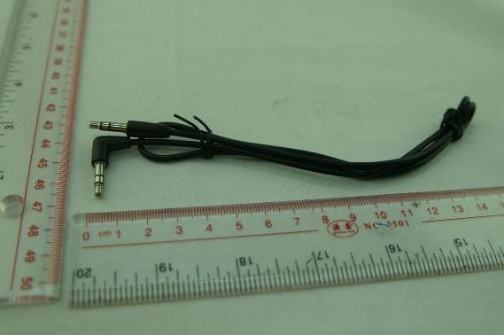
YHE-MOD39982
Aug 10, 2014iTrip Aux Bluetooth
Equipment Class
DSS - Part 15 Spread Spectrum Transmitter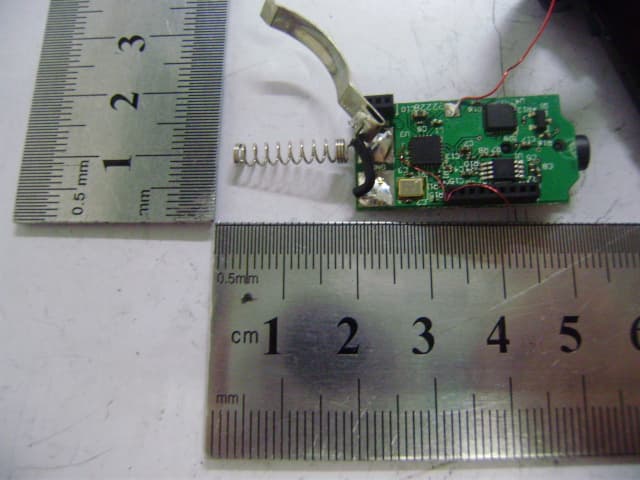
YHEP2888
Jul 31, 2011BLUETRIP DUAL CONNECT
Equipment Class
DSS - Part 15 Spread Spectrum Transmitter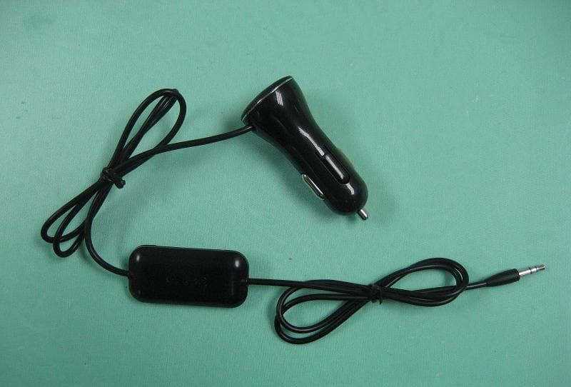
YHEP3783
May 23, 2011FM Transmitter
Equipment Class
DXX - Part 15 Low Power Communication Device Transmitter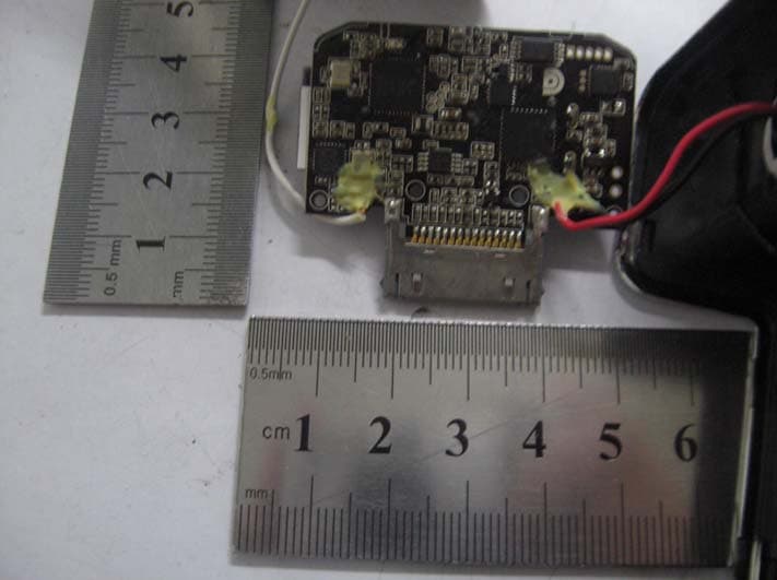
YHEP2401
Nov 07, 2010BLUETRIP
Equipment Class
DSS - Part 15 Spread Spectrum Transmitter