YJV-CHG400CHG400 MOCKINGBIRD MICROPHONE SYSTEM
Enforcement Video, LLC (d.b.a. WatchGuard Video)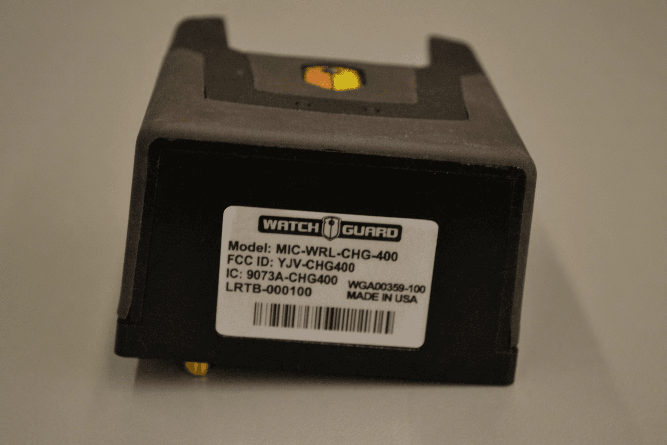
Click to zoom
Application Details
- Equipment Class
- DSS - Part 15 Spread Spectrum Transmitter
- Date of Grant
- Dec 12, 2011
- Application Purpose
- Original Equipment
- Date of Application
- Dec 12, 2011
- Equipment Note
- CHG400 MOCKINGBIRD MICROPHONE SYSTEM
- Frequency Range
- 902.25000000 - 927.50000000
- Country
- United States
Documents & Files
Document Text
Text extracted from the exhibit documents filed with the FCC. Open a document above to read the original.
Users Manual
LRT WIRELESS MICROPHONE USER GUIDE WGD00091 Revision A - 2 - WGD00091 Revision A FCC and IC Notices This equipment complies with Part 15 of the FCC rules and Industry Canada licence- exempt RSS standard(s). Any changes or modifications not expressly approved by the manufacturer could void the user's authority to operate the equipment. Cet équipement est conforme à la Partie 15 des règlements de la FCC et Industrie Canada exempts de licence standard RSS (s). Tout changement ou modification non expressément approuvée par le fabricant pourrait annuler l'autorité de l'utilisateur de faire fonctionner l'équipement. The antenna used for this device must be installed to provide a separation distance of at least 20cm from all persons and must not be co-located or operating in conjuntion with any other transmitter. This device com plies with Part 15 of the FCC rules and Industry Canada licence-exempt RSS standard(s) subject to the following two conditions: 1. This device may not cause harmful interference. 2. This device must accept all interference received, including interference that may cause undesired operation. Cet appareil est conforme à la Partie 15 des règlements de la FCC et Industrie Canada exempts de licence standard RSS (s) soumis aux deux conditions suivantes: 1. Cet appareil ne peut causer des interférences nuisibles. 2. Cet appareil doit accepter toutes les interférences reçues, y compris les interférences qui peuvent perturber le fonctionnement. WGD00091 - 3 - Revision A TABLE OF CONTENTS INTRODUCTION.......................................................................................................... 5 GENERAL OPERATION ................................................................................................ 5 INSTALLATION ........................................................................................................... 6 MOUNTING THE BASE.......................................................................................................... 6 ANTENNA CONNECTION ....................................................................................................... 6 DVR CABLE CONNECTION .................................................................................................... 7 BASE UNIT FEATURES ................................................................................................. 8 RED AND GREEN STATUS LEDS.............................................................................................. 8 BINDING A BASE WITH A TRANSMITTER ................................................................................... 8 TRANSMITTER UNIT FEATURES .................................................................................. 10 TRANSMITTER POWER ON/OFF ........................................................................................... 10 TALK/MUTE SLIDE SWITCH ................................................................................................. 10 Mute .................................................................................................. 10 STATUS INDICATORS .......................................................................................................... 11 Battery Level Indicator ..................................................................... 11 Signal Strength Indicator .................................................................. 11 Audio Status Indicator ...................................................................... 11 Mute Status ....................................................................................... 11 Backlight Status ................................................................................ 11 Vibration Mode Status ...................................................................... 12 Beeper Mode Status .......................................................................... 12 LCD BACKLIGHT CONTROL BUTTON ..................................................................................... 12 MODE BUTTON ................................................................................................................ 12 Covert Mode ..................................................................................... 13 LAPEL MICROPHONE JACK .................................................................................................. 14 TRANSMITTER BELT CLIP .................................................................................................... 14 SET UP AND OPERATION ........................................................................................... 15 BINDING THE TRANSMITTER AND BASE.................................................................................. 15 NORMAL OPERATION ........................................................................................................ 15 OUT OF RANGE ................................................................................................................ 15 LOW BATTERY WARNING ................................................................................................... 16 GUIDELINES AND RECOMMENDATIONS FOR BEST PERFORMANCE ............................ 17 - 4 - WGD00091 Revision A COMPATIBILITY................................................................................................................. 17 USING MULTIPLE WIRELESS SYSTEMS ................................................................................... 17 POTENTIAL SOURCES OF INTERFERENCE ................................................................................. 17 TECHNICAL SPECIFICATIONS ...................................................................................... 18 TROUBLESHOOTING .................................................................................................. 18 WARRANTY ............................................................................................................... 19 WGD00091 - 5 - Revision A Introduction This is the user guid…
Text truncated - open the document above for the full version.
Operational Description
MOBILE ANTENNAS Covert Antennas 16 PCTEL, Inc. WEB: www.antenna.com APDM5920U, vertical installation. The antenna can also be installed horizontally. Technical Data Maximum Power: 10 watts Polarization: Linear, horizontal or vertical Nominal Impedance: 50 ohms VSWR: < 2.0:1 Radiator Material: ABS Coax Cable: 10 ft RG-174/U cable (bottom fed) Connector SAP (female FME) Mounting Method: Normount ® Z500 tape Inside Window Glass Mount This vertical or horizontal polarization antenna is designed for inside glass mount installations operating in the 800 MHz cellular, 900 MHz trunking, 1800 MHz DCS and 1900 MHz PCS bands without the need for tuning. Its tape mount easily attaches to a vehicle’s windshield or other glass surfaces making the antenna ideal for public safety or other applications requiring an unobtrusive design. Features • Quad Band — covers 800 MHz cellular, 900 MHz trunking, 1800 MHz DCS, and 1900 MHz PCS • Low Profi le — “sleek” appearance blends well with car dash interior • Effi cient — simple mounting method allows installation in minutes without holes • Economical — one antenna serves the function of four, minimizing installa- tion and inventory requirements • Antenna can be oriented vertically or horizontally for maximum installation fl exibility Antenna Electrical Specifi cations ModelFrequency RangeGainBandwidth APDM5920U824-960/1710-1990 MHzUnity136/280 MHz Normount ® is a registered trademark of Norton, a Saint-Gobain Co. Mechanical Specifi cations ModelAntenna Dimensions APDM5920U0.5” D x 5.9” L
RF Exposure Info
Prediction of MPE limit at a given distance Equation from page 18 of OET Bulletin 65, Edition 97-01 where:S = power density P = power input to the antenna G = power gain of the antenna in the direction of interest relative to an isotropic radiator R = distance to the center of radiation of the antenna Maximum peak output power at antenna input terminal:20.83(dBm)* Maximum peak output power at antenna input terminal:121(mW) Antenna gain(maximum):-2(dBi)* Maximum antenna gain:0.630957344(numeric) Time Averaging:100(%)* Prediction distance:20(cm)* Prediction frequency:920(MHz)* MPE limit for uncontrolled exposure at prediction frequency:0.613(mW/cm^2) Power density at prediction frequency:0.015 (mW/cm^2) This equates to:0.152 W/m^2 2 4R PG S
Test Report
Nemko Test Report: 44217RUS1rev1 Applicant: WatchGuard Video 3001 Summit Ave. Plano, TX 75074 USA Equipment Under Test: MIC-WRL-CHG-400 (E.U.T.) FCC ID: YJV-CHG400 In Accordance With: FCC Part 15, Subpart C, 15.247 & Industry Canada, RSS-210, Issue 8 Frequency Hopping Transmitters Tested By: Nemko USA Inc. 802 N. Kealy Lewisville, Texas 75057-3136 TESTED BY: DATE: 15 June 2010 David Light, Senior Wireless Engineer APPROVED BY: DATE: 26 July 2011 Tom Tidwell, Telecom Direct Total Number of Pages: 37 Nemko USA, Inc. FCC PART 15, SUBPART C & Industry Canada RSS-210 FREQUENCY HOPPING SPREAD SPECTRUM TRANSMITTER EQUIPMENT: MIC-WRL-CHG-400 PROJECT NO.: 44217RUS1rev1 Page 2 of 37 Table of Contents SECTION 1. SUMMARY OF TEST RESULTS 3 SECTION 2. EQUIPMENT UNDER TEST (E.U.T.) 5 SECTION 3. CHANNEL SEPARATION 7 SECTION 4. TIME OF OCCUPANCY 10 SECTION 5. PEAK POWER OUTPUT 13 SECTION 6. SPURIOUS EMISSIONS (ANTENNA CONDUCTED) 16 SECTION 7. SPURIOUS EMISSIONS (RADIATED) 20 SECTION 8. RECEIVER SPURIOUS 25 SECTION 9. TEST EQUIPMENT LIST 26 ANNEX A - TEST DETAILS 27 ANNEX B - TEST DIAGRAMS 35 Nemko USA, Inc. FCC PART 15, SUBPART C & Industry Canada RSS-210 FREQUENCY HOPPING SPREAD SPECTRUM TRANSMITTER EQUIPMENT: MIC-WRL-CHG-400 PROJECT NO.: 44217RUS1rev1 Page 3 of 37 Section 1. Summary of Test Results Manufacturer: WatchGuard Video Model No.: MIC-WRL-CHG-400 Sample No.: 1 General: All measurements are traceable to national standards. These tests were conducted on a sample of the equipment for the purpose of demonstrating compliance with Part 15, Subpart C, Paragraph 15.247 & Industry Canada RSS-210, Issue 8 for Frequency Hopping Spread Spectrum devices. Radiated tests were conducted is accordance with ANSI C63.4-2003 and FCC Notice DA 00-705. Radiated emissions are made in a semi-anechoic chamber. A description of the test facility is on file with the FCC and Industry Canada. New Submission Production Unit Class II Permissive Change Pre-Production Unit THIS TEST REPORT RELATES ONLY TO THE ITEM(S) TESTED. THE FOLLOWING DEVIATIONS FROM, ADDITIONS TO, OR EXCLUSIONS FROM THE TEST SPECIFICATIONS HAVE BEEN MADE. See “ Summary of Test Data”. Nemko USA, Inc. authorizes the above named company to reproduce this report provided it is reproduced in its entirety, for use by the company’s employees only. This report must not be used to claim product certification, approval, or endorsement by NVLAP, NIST, or any agency of the Federal Government. Nemko USA, Inc. is a NVLAP accredited laboratory. Any use which a third party makes of this report, or any reliance on or decisions to be made based on it, are the responsibility of such third parties. Nemko USA, Inc. accepts no responsibility for damages, if any, suffered by any third party as a result of decisions made or actions based on this report. This report applies only to the items tested. Nemko USA, Inc. FCC PART 15, SUBPART C & Industry Canada RSS-210 FREQUENCY HOPPING SPREAD SPECTRUM TRANSMITTER EQUIPMENT: MIC-WRL-CHG-400 PROJECT NO.: 44217RUS1rev1 Page 4 of 37 Summary Of Test Data NAME OF TEST PARA. NO. RESULT Powerline Conducted Emissions 15.207(a)/RSS-Gen 7.2.2 NA Channel Separation 15.247(a)(1)/RSS-210 A8.1(b) Complies Time of Occupancy 15.247(a)(1)/RSS-210 A8.1(c) Complies 20 dB Occupied Bandwidth 15.247(a)(1)/RSS-210 A8.1(c) Complies Peak Power Output 15.247(b)/RSS-210 A8.4(1) Complies Spurious Emissions (Antenna Conducted) 15.247(d)(RSS-210 A8.5 NT Spurious Emissions (Radiated) 15.247(d)/RSS-210 A8.5 Complies Receiver Spurious Emissions RSS-Gen 7.2.3 Complies Footnotes: 1) The EUT is powered by 12 Vdc automotive battery. Justification for Revision: Revision 1) Updated report to current issue of RSS-210. Nemko USA, Inc. FCC PART 15, SUBPART C & Industry Canada RSS-210 FREQUENCY HOPPING SPREAD SPECTRUM TRANSMITTER EQUIPMENT: MIC-WRL-CHG-400 PROJECT NO.: 44217RUS1rev1 Page 5 of 37 Section 2. Equipment Under Test (E.U.T.) General Equipment Information Frequency Band: 902 – 928 MHz 2400 – 2483.5 MHz 5725 – 5850 MHz Operating Frequency Range: 902.25 to 927.50 MHz Modulation Type: FSK Emission Designator: 200KF1D Number of Channels: 50 to 51 Channel Spacing: 500 kHz 20 dB Bandwidth: 200 kHz Transmitter ON time: 361.62 mS in 20 seconds Input power: 12 Vdc User Frequency Adjustment: None 15.203 Antenna Restriction: The antenna installed with this radio device uses a standard SMA connector. However the use of this device is always in low enforcement vehicles and is professionally installed with the supplied antenna. Nemko USA, Inc. FCC PART 15, SUBPART C & Industry Canada RSS-210 FREQUENCY HOPPING SPREAD SPECTRUM TRANSMITTER EQUIPMENT: MIC-WRL-CHG-400 PROJECT NO.: 44217RUS1rev1 Page 6 of 37 Description of EUT Microphone system is comprised of one MIC-WRL-TRN-400 "Transmitter" component and one MIC-WRL-CHG-400 "Base" component. These two components operate as a pair and comprise the operational wireless microphone system. System Diagram Nemko USA, Inc. FCC PART 15, SUBPART C & Industry Canada RSS-210 FREQUENCY HOPPING SPREAD SPECTRUM TRANSMITTER EQUIPMENT: MIC-WRL-CHG-400 PROJECT NO.: 44217RUS1rev1 Page 7 of 37 Section 3. Channel Separation NAME OF TEST: Channel Separation PARA. NO.: 15.247(a)(1) RSS-210 A8.1(b) TESTED BY: David Light DATE: 14 June 2010 Test Results: Complies. Measurement Data: See 20 dB BW plot Measured 20 dB bandwidth: 200 kHz Channel Separation: 500 kHz Equipment Used: 1464-1082-802 Measurement Uncertainty: 1X10 -7 ppm Temperature: 22 °C Relative Humidity: 35 % Nemko USA, Inc. FCC PART 15, SUBPART C & Industry Canada RSS-210 FREQUENCY HOPPING SPREAD SPECTRUM TRANSMITTER EQUIPMENT: MIC-WRL-CHG-400 PROJECT NO.: 44217RUS1rev1 Page 8 of 37 Test Data Channel Separation Low Channel Nemko USA, Inc. FCC PART 15, SUBPART C & Industry Canada RSS-210 FREQUENCY HOPPING SPREAD SPECTRUM TRANSMITTER EQUIPMENT: MIC-WRL-CHG-400 PROJECT NO.: 44217RUS1rev1 Page 9 of 37 Test Data – 20 dB Bandwidth Mid Channel High Channel Nemko USA, Inc. FCC PART 15, SUBPART C & Industr…
Text truncated - open the document above for the full version.
Contact Information
Applicant
Jim Exner
Test Firm
Nemko Dallas, Inc.Mike Cantwell
Technical Specifications
| # | Rule Parts | Frequency Range | Power Output |
|---|---|---|---|
| 1 | 15C | 902.25 MHz - 927.5 MHz | 121.00 mW |
Other Applications from Enforcement Video, LLC (d.b.a. WatchGuard Video)
YJV-TRN420
Jun 04, 2020MIC-WRL-TRN-420
Equipment Class
DSS - Part 15 Spread Spectrum Transmitter
YJV-VST500
Mar 25, 2020WFB2
Equipment Class
DTS - Digital Transmission System
YJV-VST400
Mar 24, 2020V300
Equipment Class
DSS - Part 15 Spread Spectrum Transmitter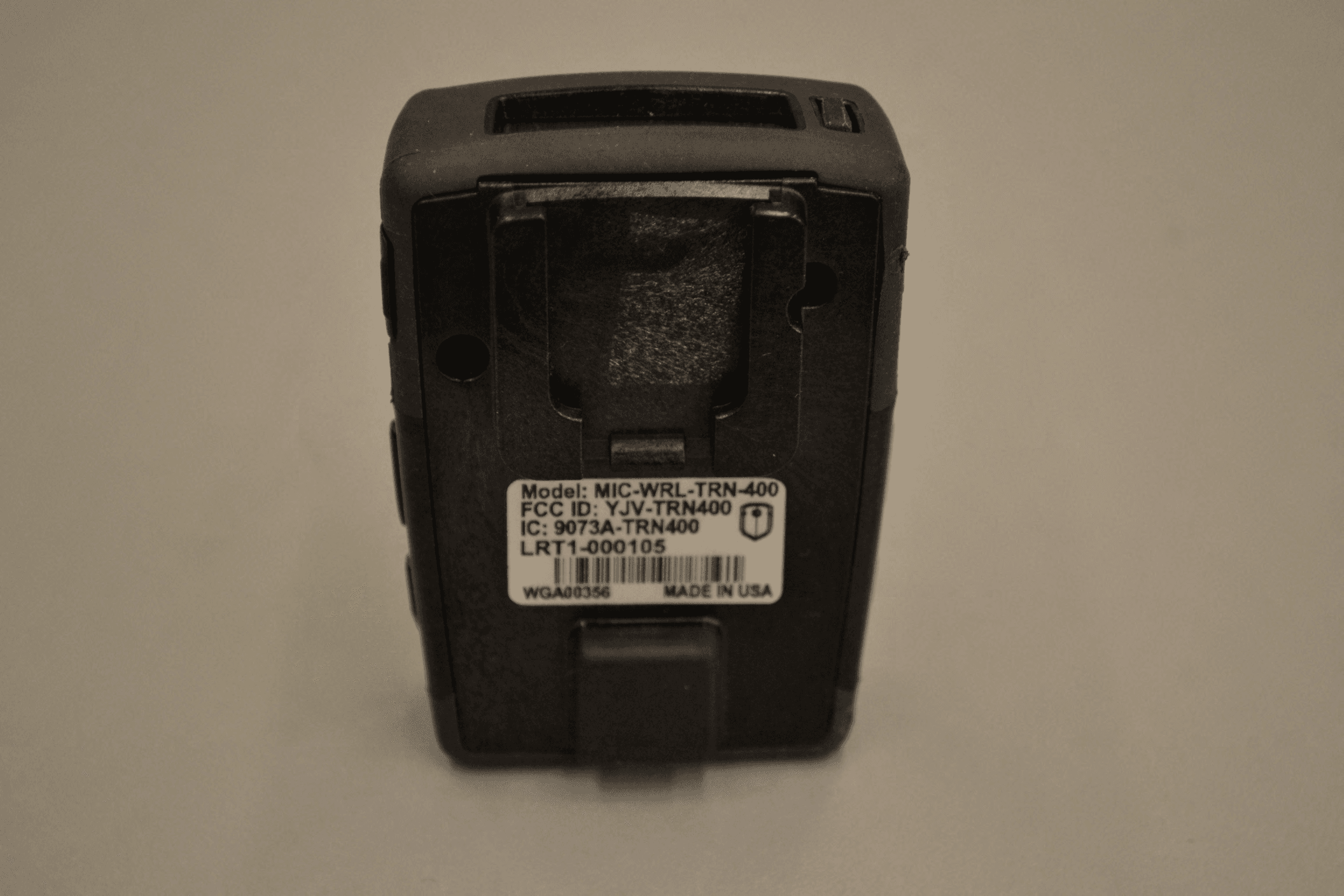
YJV-TRN400
Dec 20, 2011TRN400 MOCKINGBIRD MICROPHONE SYSTEM
Equipment Class
DSS - Part 15 Spread Spectrum Transmitter