YJV-TRN400TRN400 MOCKINGBIRD MICROPHONE SYSTEM
Enforcement Video, LLC (d.b.a. WatchGuard Video)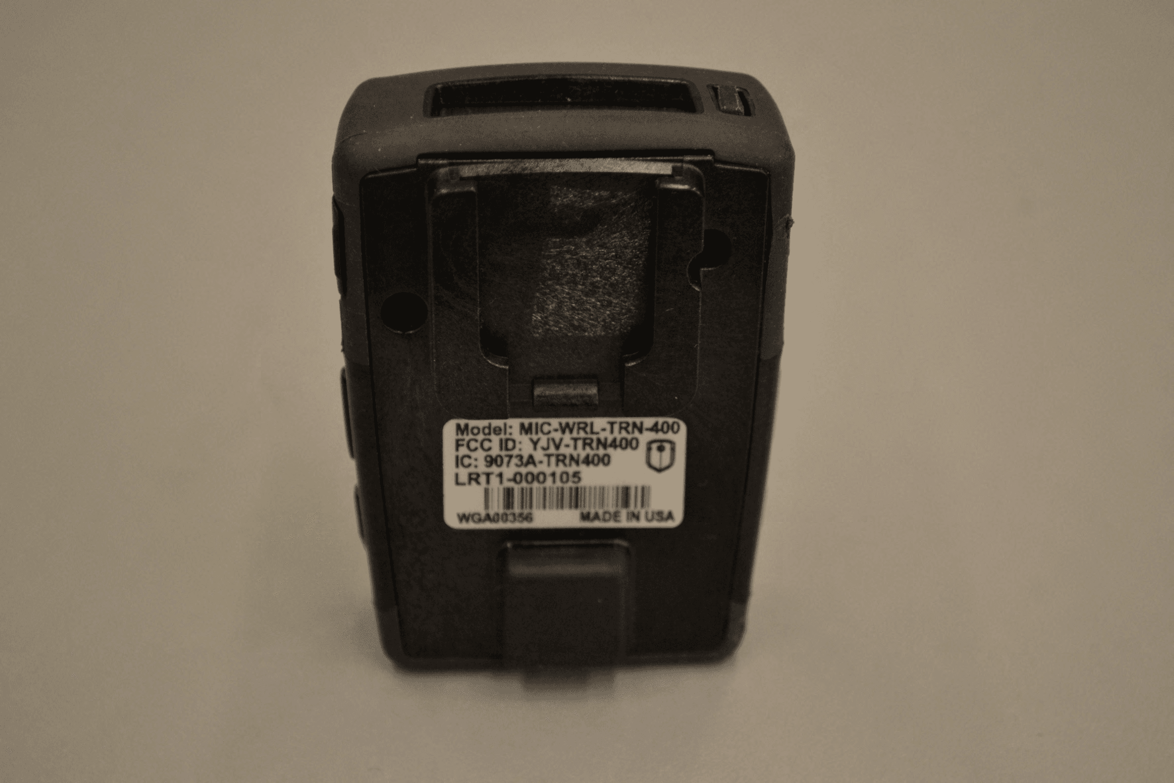
Click to zoom
Application Details
- Equipment Class
- DSS - Part 15 Spread Spectrum Transmitter
- Date of Grant
- Dec 20, 2011
- Application Purpose
- Original Equipment
- Date of Application
- Dec 20, 2011
- Equipment Note
- TRN400 MOCKINGBIRD MICROPHONE SYSTEM
- Frequency Range
- 902.25000000 - 927.50000000
- Country
- United States
Documents & Files
Document Text
Text extracted from the exhibit documents filed with the FCC. Open a document above to read the original.
Users Manual
High Fidelity Wireless Microphone USER GUIDE WGD00091 Revision B - 2 - WGD00091 Revision B FCC and IC Notices This equipment complies with Part 15 of the FCC rules and Industry Canada licence- exempt RSS standard(s). Any changes or modifications not expressly approved by the manufacturer could void the user's authority to operate the equipment. Cet équipement est conforme à la Partie 15 des règlements de la FCC et Industrie Canada exempts de licence standard RSS (s). Tout changement ou modification non expressément approuvée par le fabricant pourrait annuler l'autorité de l'utilisateur de faire fonctionner l'équipement. This device complies with Part 15 of the FCC rules and Industry Canada licence-exempt RSS standard(s) subject to the following two conditions: 1. This device may not cause harmful interference. 2. This device must accept all interference received, including interference that may cause undesired operation. Cet appareil est conforme à la Partie 15 des règlements de la FCC et Industrie Canada exempts de licence standard RSS (s) soumis aux deux conditions suivantes: 1. Cet appareil ne peut causer des interférences nuisibles. 2. Cet appareil doit accepter toutes les interférences reçues, y compris les interférences qui peuvent perturber le fonctionnement. WGD00091 - 3 - Revision B TABLE OF CONTENTS INTRODUCTION.......................................................................................................... 4 GENERAL OPERATION ................................................................................................ 4 BASE UNIT ................................................................................................................. 5 Antenna Connection............................................................................ 6 Red and Green Status LEDs ............................................................... 6 DVR Cable Connection ...................................................................... 6 SYSTEM CONTROLS AND FEATURES ............................................................................ 7 TRANSMITTER UNIT ............................................................................................................ 7 TALK/MUTE Slide Switch ................................................................ 8 Mode Button ....................................................................................... 8 LCD Backlight Control Button ........................................................... 8 Covert Mode ....................................................................................... 8 External Microphone Jack .................................................................. 9 Transmitter Power On/Off .................................................................. 9 SET UP AND OPERATION .............................................................................................. 10 Synchronizing the Transmitter and Base .......................................... 10 Normal Operation ............................................................................. 10 Out of Range ..................................................................................... 11 Low Battery Warning ....................................................................... 11 GUIDELINES AND RECOMMENDATIONS FOR BEST PERFORMANCE ............................ 12 Compatibility .................................................................................... 12 Using Multiple Wireless Systems ..................................................... 12 Potential Sources of Interference ...................................................... 12 TROUBLESHOOTING .................................................................................................. 13 WARRANTY ............................................................................................................... 16 - 4 - WGD00091 Revision B Introduction This is the user guide for the WatchGuard Video Long Range Transmitter (LRT) Wireless Microphone. The LRT Microphone is a specialized device designed to be used exclusively with WatchGuard’s family of vehicle-based digital video recorder (DVR) products. This Guide’s purpose is to describe the proper connection, installation and use of the LRT Microphone. General Operation The LRT connects directly to all WatchGuard DVR products to supply one of the audio tracks during the video recording process. The LRT microphone is a system with two primary devices; the Transmitter and the Base. The user (for example, a police officer) will wear the Transmitter device on their body. This device should be attached to the user’s belt with one of the two available spring-loaded clips. Like the DVR, the LRT Base device mounts in a vehicle using one of several brackets and attaches to the DVR using a cable. The Base device also requires an antenna connection to provide the wireless radio link to the Transmitter device. This antenna is supplied as part of the LRT microphone system and mounts to the vehicle windshield using an adhesive. Base Unit WGD00091 - 5 - Revision B - 6 - WGD00091 Revision B Antenna Connection Connect the window mount antenna at this point. Only 900MHz antennas available from WatchGuard Video should be used. Wireless performance and audio quality will be affected if a non-approved antenna is used. Warning: The RP-SMA connector should be finger tightened only. No hand tools should be used when making the antenna connection. Red and Green Status LEDs The green LED on the Base will light when communicating with the Transmitter device. The LED will light solid green when the voice recording is enabled. The LED will flash when the Base is attempting to synchronize (bind) with the Transmitter. The red LED on the Base will light only when the transmitter is inserted into the base. The LED will light red when the battery is charging and green when the battery is fully charged. As the transmitter approaches full charge, this LED will slo…
Text truncated - open the document above for the full version.
Operational Description
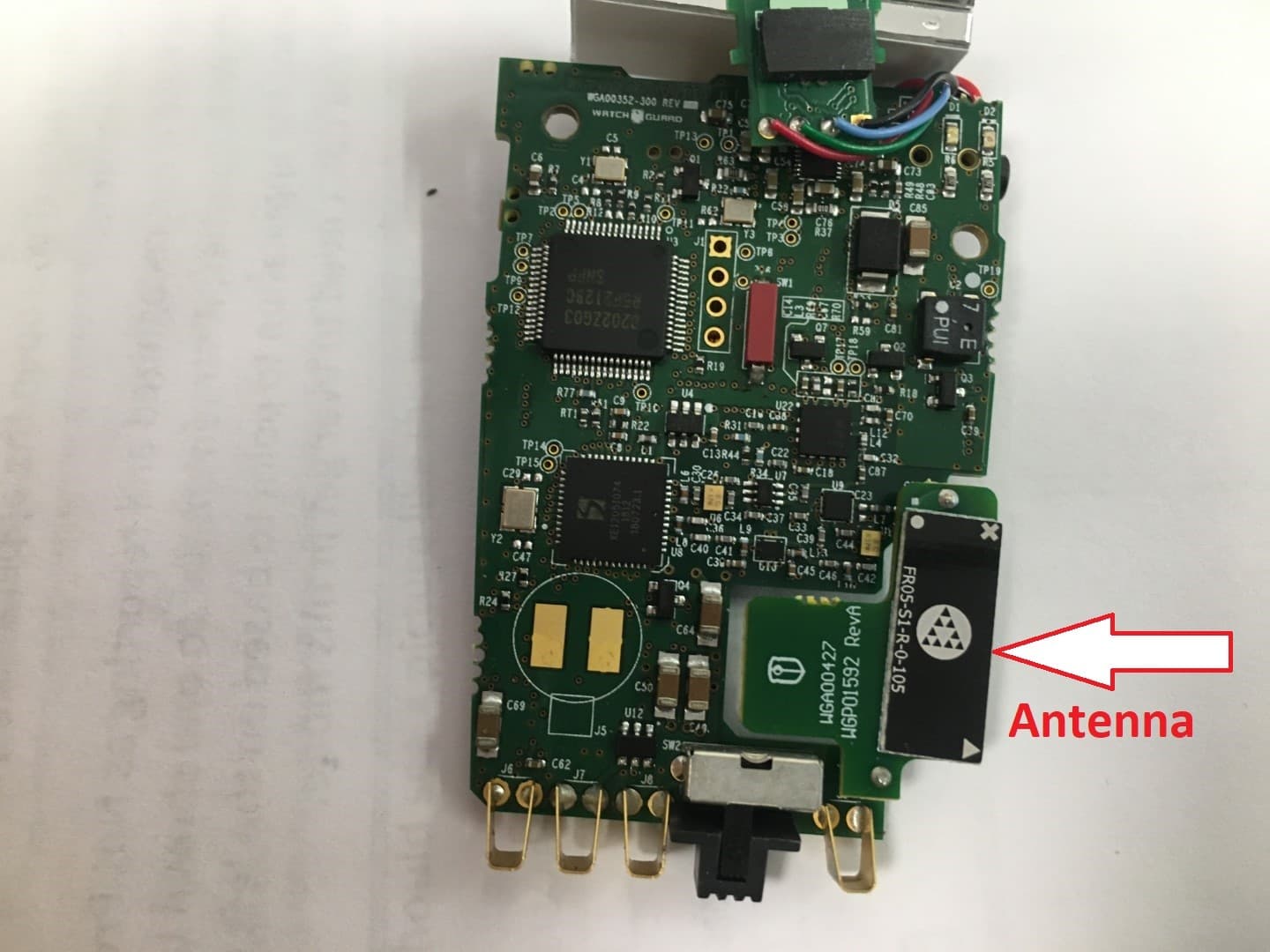
V S W R Optimised Antennas for Wireless Devices DATA SHEET · PRODUCTS & SERVICES Small SMD chip antenna for low consumption, small form-factor Zigbee TM devices Fractus specialises in enabling effective mobile communications. Using fractal technology, we design and manufacture optimised antennas to make your wireless devices more competitive. Our mission is to help our clients develop innovative products and accelerate their time to market through our expertise in antenna design, testing and manufacturing. Fractus ® EZConnect TM Zigbee TM Chip Antenna The Fractus EZConnect Zigbee Chip Antenna is a compact rectangular antenna suitable for smart home, security and other industrial devices using the 915 MHz ISM band, where low power consumption and cost are top of mind.Taking advantage of the space-filling properties of fractals, this compact monopole antenna is ideal for use within indoor (highly scattered) as well as outdoor environments. The Fractus EZConnect Zigbee Chip Antenna speeds your time to market by allowing you to easily integrate it within your industrial design (SMD mounting). 18 x 7.3 x 1 mm (image larger than actual size) Front Back P/N: FR05-S1-R-0-105 Product Benefits Small form factor Allows integration into space limited areas easily and effectively. Broad bandwidth Ensures robust performance in different PCB dimensions and plastic housing, without the need for a matching n etwork. High performance Optimises power consumption and increases device range. Omnidirectional pattern Increases device robustness due to a uniform radiation pattern. This product is protected by at least the following patents PAT. US 7,148,850, US 7,202,822 and other domestic and international patents pending 4 3.5 3 2.5 2 1.5 Frequency Range Efficiency Peak G ain VSWR Weight Temperature Impedance Dimensions 902 - 928 MHz > 40 % > 0 dBi < 2:1 0.20 g -40 to +85 °C 50 Ω unbalanced 18 x 7.3 x 1 mm 1 8 8.2 8.4 8.6 8.8 9 9.2 9.4 9.6 9.8 10 Frequency (x10 2 MHz) Measured results from a standard PCB of 121x65 mm Please contact your sales representative at [email protected] to obtain additional information. Fractus: www.fractus.com © 2010 FRACTUS, S.A. All rights reserved. Fractus and the Fractus logo are either registered trademarks or trademarks of FRACTUS, S.A. All other trademarks are the property of their respective owners. Information contained within this document is subject to change without prior notice.
RF Exposure Info
© 2011 RF Exposure Lab, LLC This report shall not be reproduced except in full without the written approval of RF Exposure Lab, LLC. 802 N. Twin Oaks Valley Road, Suite 105 • San Marcos, CA 92069 • U.S.A. TEL (760) 471-2100 • FAX (760) 471-2121 http://www.rfexposurelab.com CERTIFICATE OF COMPLIANCE SAR EVALUATION WatchGuard Video Dates of Test: December 15, 2011 3001 Summit Ave. Test Report Number: SAR.20111202 Plano, TX 75074 Revision B This wireless mobile and/or portable device has been shown to be compliant for localized specific absorption rate (SAR) for uncontrolled environment/general exposure limits specified in ANSI/IEEE Std. C95.1-1992 and had been tested in accordance with the measurement procedures specified in IEEE 1528-2003, and OET Bulletin 65 Supp. C (See test report). I attest to the accuracy of the data. All measurements were performed by myself or were made under my supervision and are correct to the best of my knowledge and belief. I assume full responsibility for the completeness of these measurements and vouch for the qualifications of all persons taking them. RF Exposure Lab, LLC certifies that no party to this application is subject to a denial of Federal benefits that includes FCC benefits pursuant to Section 5301 of the Anti-Drug Abuse Act of 1988, 21 U.S.C. 853(a). Jay M. Moulton Vice President Certificate # 2387.01 FCC ID: YJV-TRN400 IC Certificate: 9073A-TRN400 Model(s): MIC-WRL-TRN-400 Test Sample: Production Unit Serial Number: LRT1-A00226 Equipment Type: Wireless Video Control Classification: Portable Transmitter Next to Body TX Frequency Range: 902 – 928 MHz Frequency Tolerance: ± 2.5 ppm Maximum RF Output: 915 MHz – 16.7 dB Conducted Signal Modulation: FSK Antenna Type: Internal Application Type: Certification FCC Rule Parts: Part 2, 15C KDB Test Methodology: KDB 447498 Industry Canada: RSS-102, Safety Code 6 Maximum SAR Value: 1.297 W/kg Separation Distance: 0 mm FCC ID: YJV-TRN400 © 2011 RF Exposure Lab, LLC Page 2 of 64 This report shall not be reproduced except in full without the written approval of RF Exposure Lab, LLC. Table of Contents 1. Introduction ........................................................................................................................... 3 SAR Definition [5] ...................................................................................................................... 3 2. SAR Measurement Setup ..................................................................................................... 4 Robotic System ......................................................................................................................... 4 System Hardware ..................................................................................................................... 4 System Description ................................................................................................................... 4 E-Field Probe ............................................................................................................................ 5 3. Robot Specifications ............................................................................................................. 7 4. Probe and Dipole Calibration ................................................................................................ 8 5. Phantom & Simulating Tissue Specifications ........................................................................ 9 SAM Phantom ........................................................................................................................... 9 Head & Body Simulating Mixture Characterization ................................................................... 9 Device Holder ........................................................................................................................... 9 6. ANSI/IEEE C95.1 – 1992 RF Exposure Limits [2] ............................................................... 10 Uncontrolled Environment ....................................................................................................... 10 Controlled Environment .......................................................................................................... 10 7. Measurement Uncertainty ................................................................................................... 11 8. System Validation ............................................................................................................... 12 Tissue Verification ................................................................................................................... 12 Test System Verification ......................................................................................................... 12 9. SAR Test Data Summary .................................................................................................... 13 Procedures Used To Establish Test Signal ............................................................................. 13 Device Test Condition ............................................................................................................. 13 SAR Data Summary – 915 MHz Body .................................................................................... 14 SAR Data Summary – 915 MHz Body .................................................................................... 14 10. Test Equipment List ........................................................................................................ 15 11. Conclusion ...................................................................................................................... 16 12. References ...................................................................................................................... 17 Appendix A – System Validation Plots and Data ........................................................................ 18 Appendix B – SAR Test Data Plots ...............................…
Text truncated - open the document above for the full version.
RF Exposure Info
Prediction of MPE limit at a given distance Equation from page 18 of OET Bulletin 65, Edition 97-01 where:S = power density P = power input to the antenna G = power gain of the antenna in the direction of interest relative to an isotropic radiator R = distance to the center of radiation of the antenna Maximum peak output power at antenna input terminal:22.30(dBm)* Maximum peak output power at antenna input terminal:170(mW) Antenna gain(maximum):-10(dBi)* Maximum antenna gain:0.1(numeric) Time Averaging:100(%)* Prediction distance:20(cm)* Prediction frequency:920(MHz)* MPE limit for uncontrolled exposure at prediction frequency:0.613(mW/cm^2) Power density at prediction frequency:0.003(mW/cm^2) This equates to:0.034W/m^2 2 4R PG S
RF Exposure Info
© 2011 RF Exposure Lab, LLC This report shall not be reproduced except in full without the written approval of RF Exposure Lab, LLC. 802 N. Twin Oaks Valley Road, Suite 105 • San Marcos, CA 92069 • U.S.A. TEL (760) 471-2100 • FAX (760) 471-2121 http://www.rfexposurelab.com CERTIFICATE OF COMPLIANCE SAR EVALUATION WatchGuard Video Dates of Test: December 15, 2011 3001 Summit Ave. Test Report Number: SAR.20111202 Plano, TX 75074 Revision B This wireless mobile and/or portable device has been shown to be compliant for localized specific absorption rate (SAR) for uncontrolled environment/general exposure limits specified in ANSI/IEEE Std. C95.1-1992 and had been tested in accordance with the measurement procedures specified in IEEE 1528-2003, and OET Bulletin 65 Supp. C (See test report). I attest to the accuracy of the data. All measurements were performed by myself or were made under my supervision and are correct to the best of my knowledge and belief. I assume full responsibility for the completeness of these measurements and vouch for the qualifications of all persons taking them. RF Exposure Lab, LLC certifies that no party to this application is subject to a denial of Federal benefits that includes FCC benefits pursuant to Section 5301 of the Anti-Drug Abuse Act of 1988, 21 U.S.C. 853(a). Jay M. Moulton Vice President Certificate # 2387.01 FCC ID: YJV-TRN400 IC Certificate: 9073A-TRN400 Model(s): MIC-WRL-TRN-400 Test Sample: Production Unit Serial Number: LRT1-A00226 Equipment Type: Wireless Video Control Classification: Portable Transmitter Next to Body TX Frequency Range: 902 – 928 MHz Frequency Tolerance: ± 2.5 ppm Maximum RF Output: 915 MHz – 16.7 dB Conducted Signal Modulation: FSK Antenna Type: Internal Application Type: Certification FCC Rule Parts: Part 2, 15C KDB Test Methodology: KDB 447498 Industry Canada: RSS-102, Safety Code 6 Maximum SAR Value: 1.297 W/kg Separation Distance: 0 mm FCC ID: YJV-TRN400 © 2011 RF Exposure Lab, LLC Page 2 of 64 This report shall not be reproduced except in full without the written approval of RF Exposure Lab, LLC. Table of Contents 1. Introduction ........................................................................................................................... 3 SAR Definition [5] ...................................................................................................................... 3 2. SAR Measurement Setup ..................................................................................................... 4 Robotic System ......................................................................................................................... 4 System Hardware ..................................................................................................................... 4 System Description ................................................................................................................... 4 E-Field Probe ............................................................................................................................ 5 3. Robot Specifications ............................................................................................................. 7 4. Probe and Dipole Calibration ................................................................................................ 8 5. Phantom & Simulating Tissue Specifications ........................................................................ 9 SAM Phantom ........................................................................................................................... 9 Head & Body Simulating Mixture Characterization ................................................................... 9 Device Holder ........................................................................................................................... 9 6. ANSI/IEEE C95.1 – 1992 RF Exposure Limits [2] ............................................................... 10 Uncontrolled Environment ....................................................................................................... 10 Controlled Environment .......................................................................................................... 10 7. Measurement Uncertainty ................................................................................................... 11 8. System Validation ............................................................................................................... 12 Tissue Verification ................................................................................................................... 12 Test System Verification ......................................................................................................... 12 9. SAR Test Data Summary .................................................................................................... 13 Procedures Used To Establish Test Signal ............................................................................. 13 Device Test Condition ............................................................................................................. 13 SAR Data Summary – 915 MHz Body .................................................................................... 14 SAR Data Summary – 915 MHz Body .................................................................................... 14 10. Test Equipment List ........................................................................................................ 15 11. Conclusion ...................................................................................................................... 16 12. References ...................................................................................................................... 17 Appendix A – System Validation Plots and Data ........................................................................ 18 Appendix B – SAR Test Data Plots ...............................…
Text truncated - open the document above for the full version.
Contact Information
Applicant
Jim Exner
Test Firm
Nemko Dallas, Inc.Mike Cantwell
Technical Specifications
| # | Rule Parts | Frequency Range | Power Output |
|---|---|---|---|
| 1 | 15C | 902.25 MHz - 927.5 MHz | 169.00 mW |
Other Applications from Enforcement Video, LLC (d.b.a. WatchGuard Video)
YJV-TRN420
Jun 04, 2020MIC-WRL-TRN-420
Equipment Class
DSS - Part 15 Spread Spectrum Transmitter
YJV-VST500
Mar 25, 2020WFB2
Equipment Class
DTS - Digital Transmission System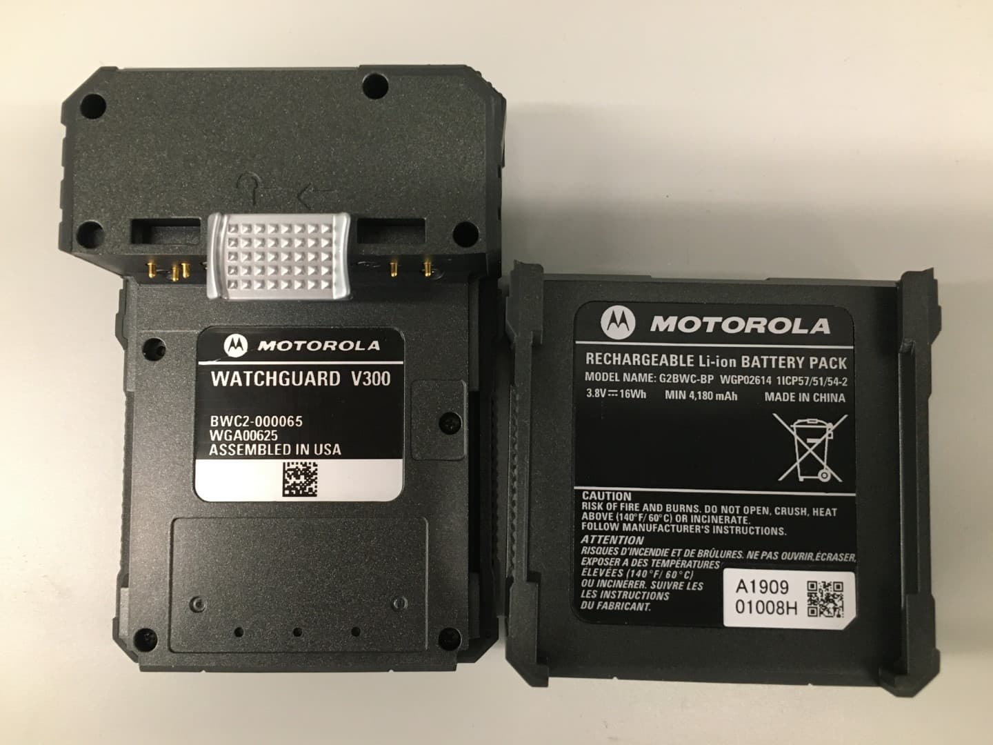
YJV-VST400
Mar 24, 2020V300
Equipment Class
DSS - Part 15 Spread Spectrum Transmitter
YJV-CHG400
Dec 12, 2011CHG400 MOCKINGBIRD MICROPHONE SYSTEM
Equipment Class
DSS - Part 15 Spread Spectrum Transmitter