YPG-MB109Dry Erase Weather Board
Oregon Scientific Global Distribution Limited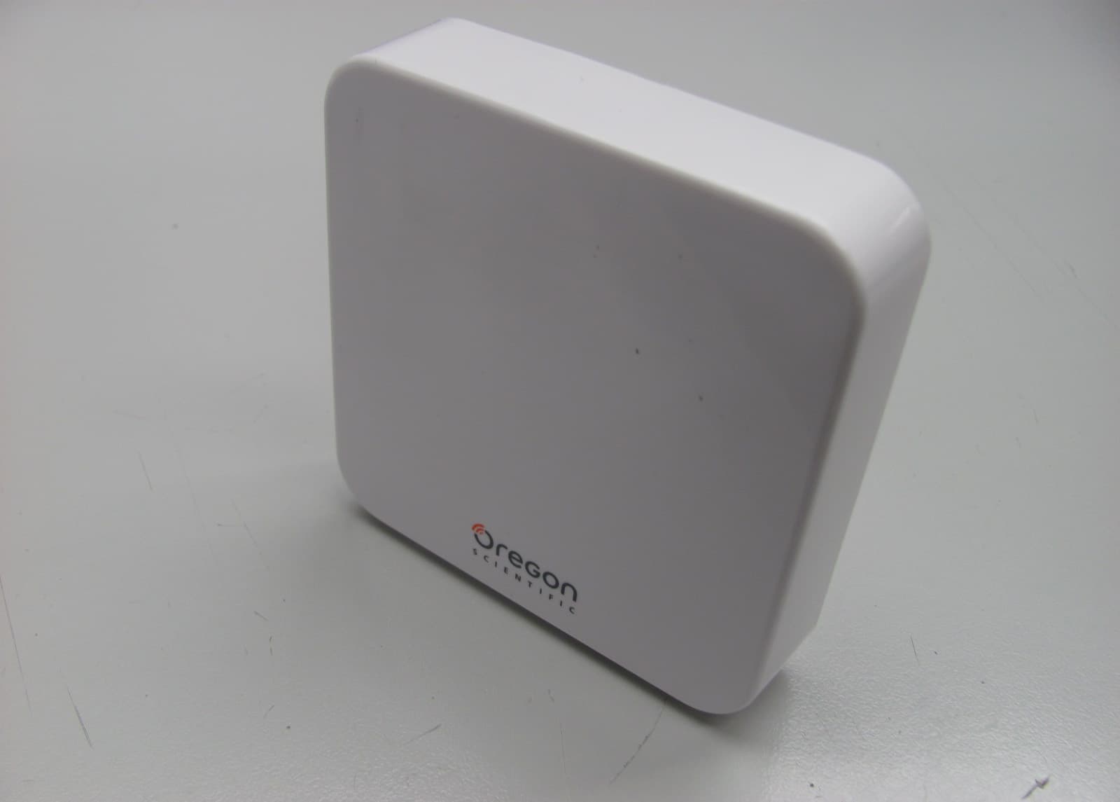
Click to zoom
Application Details
- Equipment Class
- DSC - Part 15 Security/Remote Control Transmitter
- Date of Grant
- Jan 18, 2012
- Application Purpose
- Original Equipment
- Date of Application
- Jan 17, 2012
- Equipment Note
- Dry Erase Weather Board
- Frequency Range
- 433.92000000 - 433.92000000
- Country
- Hong Kong
Documents & Files
Document Text
Text extracted from the exhibit documents filed with the FCC. Open a document above to read the original.
Users Manual
Weatherboard Model: MB108 User Manual OVERVIEW FRONT VIEW 1. Weather forecast 2. : main unit batteries low 3. Maximum or minimum temperature is displayed 4. Indoor temperature is displayed 5. : remote sensor batteries low 6. : remote sensor reception indicator 7. IN / OUT TEMP: toggle between current / indoor / outdoor temperature 8. MIN / MAX: view minimum and maximum indoor / outdoor temperature 9. Whiteboard marker tray BACK VIEW 1. Battery compartment 2. SENSOR: initiate search for sensor 3. °C / °F: select temperature unit 4. RESET: reset unit to default settings 5. Wall mount hole SENSOR 1. Battery compartment 2. Wall mount hole 3. RESET: return to default settings GETTING STARTED MAIN UNIT INSTALLATION Insert batteries: 1. Remove the battery compartment cover. 2. Insert batteries, matching the polarities (+/-). NOTE Batteries should not be exposed to excessive heat such as sunshine or fire. REMOTE SENSOR INSTALLATION 1. Using Philips screwdriver, open battery compartment door. 2. Insert batteries, matching the polarities (+/-). 3. Replace screw and close the battery door. NOTE Use alkaline batteries for longer usage and consumer grade lithium batteries in temperatures below freezing. The sensor reception icon shows the status: ICONSMEANING Main unit is searching for sensor(s) No sensor found After every sensor initialization, the main unit may take up to 4 minutes to receive the data from the sensor. If search fails, initiate another search by pressing RESET on the sensor and SENSOR on the main unit POSITIONING PRODUCT MAIN UNIT Mounting with screws: 1. Find a suitable location to mount the unit. 2. Using a pencil, mark where the screws should be using below dimensions as a guide. Horizontal 2.9 in (73.6 mm) Vertical 2.4 in (60 mm) 73.6 60.0 3. Place wall mount bracket onto wall in desired position making sure the arrow is pointing up, 4. Take out screws from packaging. Using Philips screwdriver, screw wall mount bracket onto wall. 5. Hang Weatherboard on the wall mount bracket hooks. Mounting with sticker: Recommended for flat surfaces made of glass or metal. Do not mount on wood surfaces or those with paint finishing. 1. Wipe the wall surface and the wall mount bracket where the sticker will be. 2. Peel away adhesive paper from one side of the sticker, being careful not to let the glue stick to anything. 3. Position sticker on wall mount bracket and press down firmly for about 20-30 seconds. 4. Peel away the other adhesive paper. Position wall mount bracket in desired location making sure the arrow is pointing up. Press firmly for about 20-30 seconds. 5. Hang Weatherboard on the wall mount bracket hooks. SENSOR Secure the sensor in the desired location using the wall mount hole or stand. TIP Ideal placements for the sensor would be in any location on the exterior of the home at a height of not more than 1.5 m (5 ft) and which can shield it from direct sunlight or wet conditions for an accurate reading. 1.5m (5ft) For best results: • Place the sensor within 40 m (131 ft) of the main unit. • Place the sensor out of direct sunlight and moisture. • Position the sensor so that it faces the main unit, minimizing obstructions such as doors, walls and furniture. • Place the sensor in a location with a clear view to the sky, away from metallic / electronic objects. • Position the sensor close to the main unit during cold winter months as below- freezing temperatures may affect battery performance and signal transmission. TIP The transmission range may vary depending on many factors. You may need to experiment with various locations to get the best results. TEMPERATURE To toggle temperature unit: • Slide °C / °F switch to select. To toggle between indoor / outdoor temperature display: • Press IN / OUT TEMP. To view minimum and maximum temperature records: • Press MIN / MAX repeatedly. WEATHER FORECAST This product forecasts the next 12 to 24 hours of weather forecast within a 30-50 km (19-31 mile) radius. SunnyCloudyRainy CLEANING THE WEATHERBOARD IMPORTANT Only use whiteboard markers. NEVER use permanent markers on the Weatherboard. To keep the Weatherboard in top condition, use a whiteboard eraser to wipe away ink immediately after use. RESET Press RESET to return to the default settings. TROUBLESHOOTING DISPLAYAREAPROBLEM LL.LTemperatureReading is below range HH.HTemperatureReading is above range SPECIFICATIONS MAIN UNIT TYPEDESCRIPTION L x W x H 8 x 0.9 x 9 in (203 x 23 x 228 mm) Weight 243g ( oz) without battery and wall mount bracket Tempera- ture range -5°C to 50°C (23°F to 122°F) Signal frequency 433 MHz Power 2 x UM-4 (AAA) 1.5 V batteries (not included) SENSOR TYPEDESCRIPTION L x W x H 3 x 1 x 3 in (75 x 25.6 x 76 mm) Weight 53.7g without battery Temperature range -20°C to 60°C (-4°F to 140°F) Transmis- sion range 40 m (131 ft) unob- structed Power 2 x UM-4 (AAA) 1.5 V batteries (not included) PRECAUTIONS • Do not subject the unit to excessive force, shock, dust, temperature or humidity. • Do not cover the ventilation holes with any items such as newspapers, curtains etc. • Do not immerse the unit in water. If you spill liquid over it, dry it immediately with a soft, lint-free cloth. • Do not clean the unit with abrasive or corrosive materials. • Do not tamper with the unit’s internal components. This invalidates the warranty. • Only use fresh batteries. Do not mix new and old batteries. • Images shown in this manual may differ from the actual display. • When disposing of this product, ensure it is collected separately for special treatment and not as normal household waste. • Placement of this product on certain types of wood may result in damage to its finish for which Oregon Scientific will not be responsible. Consult the furniture manufacturer’s care instructions for information. • The contents of this manual may not be reproduced without the permission of the manufacturer. • Do not dispose old batteries as unsorted municipal waste. Collection of such waste separately for sp…
Text truncated - open the document above for the full version.
External Photos
INTERTEK TESTING SERVICE Report No.: HK12010272-1 FCC ID: YPG-MB109 Equipment Photographs Model : MB 109 (External)
Internal Photos
INTERTEK TESTING SERVICE Report No.: HK12010272-1 FCC ID: YPG-MB109 Equipment Photographs Model: MB 109 (Internal) INTERTEK TESTING SERVICE Report No.: HK12010272-1 FCC ID: YPG-MB109 Equipment Photographs Model: MB 109 (Internal) INTERTEK TESTING SERVICE Report No.: HK12010272-1 FCC ID: YPG-MB109 Equipment Photographs Model: MB 109 (Internal) INTERTEK TESTING SERVICE Report No.: HK12010272-1 FCC ID: YPG-MB109 Equipment Photographs Model: MB 109 (Internal)
Operational Description
Transmitter (Sensor) FCC ID: YPG-MB109 Technical Description NTC and associated circuit form the temperature sensing circuit. S1 is a reset button for system reset. R1, R5 and Q1 act as low battery detection circuit. When the battery is low, the MCU will send a battery low signal to the receiver and display on the receiver LCD display. C7, C9, L1, L2, L3 & L4 act as antenna matching network. RF Resonator SAW1 (433.92MHz ), Q2 and associated circuit act as ASK modulator. U1 is coding MCU. Crystal XTI (32768Hz) generates system clock for the MCU (U1). The duration of each transmission is 980ms period and the silent period between each transmission is 59 seconds. The transmitter is powered by two ‘AAA’ batteries. Antenna Type: Integral, Internal Modulation: ASK (433.92MHz , single channel)
Test Report
- The test report only allows to be revised within the retention period unless further standard or the requirement was noticed. - This report is for the exclusive use of Intertek's Client and is provided pursuant to the agreement between Intertek and its Client. Intertek's responsibility and liability are limited to the terms and conditions of the agreement. Intertek assumes no liability to any party, other than to the Client in accordance with the agreement, for any loss, expense or damage occasioned by the use of this report. Only the Client is authorized to permit copying or distribution of this report and then only in its entirety. Any use of the Intertek name or one of its marks for the sale or advertisement of the tested material, product or service must first be approved in writing by Intertek. The observations and test results in this report are relevant only to the sample tested. This report by itself does not imply that the material, product, or service is or has ever been under an Intertek certification program. Intertek Testing Services Hong Kong Ltd. 2/F., Garment Centre, 576 Castle Peak Road, Kowloon, Hong Kong. Tel: (852) 2173 8888 Fax: (852) 2785 5487 Website: www.hk.intertek-etlsemko.com TEST REPORT Report No.: HK12010272-1 Oregon Scientific Global Distribution Limited Application For Certification (Original Grant) (FCC ID: YPG-MB109) Transmitter Prepared and Checked by: Approved by: Signed On File Wong Cheuk Ho, Herbert Engineer Wong Kwok Yeung, Kenneth Lead Engineer Date: January 18, 2012 INTERTEK TESTING SERVICES Report No.: HK12010272-1 FCC ID: YPG-MB109 i GENERAL INFORMATION Oregon Scientific Global Distribution Limited BRAND NAME: Oregon Scientific, MODEL: MB 109 FCC ID: YPG-MB109 Grantee: Oregon Scientific Global Distribution Limited Grantee Address: Block C, 9/F., Kaiser Estate, Phase 1, 41 Man Yue Street, Hunghom, Kowloon, Hong Kong. Contact Person: Mr. Ken Lee Tel: 852-27651812 Fax: 852-27657435 e-mail: [email protected] Manufacturer: Venture Global Limited Manufacturer Address: Unit 2506, 25/F., Star Centre, 433-451 Castle Peak Road, Kwai Chung, N.T., Hong Kong. Brand Name: Oregon Scientific Model: MB 109 Type of EUT: Transmitter Description of EUT: Dry Erase Weather Board Serial Number: N/A FCC ID: YPG-MB109 Date of Sample Submitted: January 09, 2012 Date of Test: January 11, 2012 Report No.: HK12010272-1 Report Date: January 18, 2012 Environmental Conditions: Temperature: +10 to 40°C Humidity: 10 to 90% INTERTEK TESTING SERVICES Report No.: HK12010272-1 FCC ID: YPG-MB109 ii SUMMARY OF TEST RESULT Oregon Scientific Global Distribution Limited BRAND NAME: Oregon Scientific, MODEL: MB 109 FCC ID: YPG-MB109 TEST SPECIFICATION REFERENCE RESULTS Maximum Peak Output Power 15.247(b), (c) / RSS-210 A8.4 N/A Hopping Channel Carrier Frequencies Separation 15.247(e) / RSS-210 A8.1 N/A 20dB Bandwidth of the Hopping Channel 15.247(a) / RSS-210 A8.1 N/A Number of Hopping Frequencies 15.247(e) / RSS-210 A8.1 N/A Average Time of Occupancy of Hopping Frequency 15.247(e) / RSS-210 A8.1 N/A Antenna Conducted Spurious Emissions 15.247(d) / RSS-210 A8.5 N/A Radiated Spurious Emissions 15.247(d) / RSS-210 A8.5 N/A RF Exposure Compliance 15.247(i) / RSS-Gen 5.6 N/A Transmitter Power Line Conducted Emissions 15.207 / RSS-Gen 7.2.4 N/A Transmitter Field Strength 15.227 / RSS-310 3.8 N/A Transmitter Field Strength 15.229 / RSS-210 A2.7 N/A Transmitter Field Strength, Bandwidth and Timing Requirement 15.231(a) / RSS-210 A1.1.1 N/A Transmitter Field Strength, Bandwidth and Timing Requirement 15.231(e) / RSS-210 A1.1.5 Pass Transmitter Field Strength and Bandwidth Requirement 15.239 / RSS-210 A2.8 N/A Transmitter Field Strength and Bandwidth Requirement 15.249 / RSS-210 A2.9 N/A Transmitter Field Strength and Bandwidth Requirement 15.235 / RSS-310 3.9 N/A Receiver / Digital Device Radiated Emissions 15.109 / RSS-210 2.5 N/A Digital Device Conducted Emissions 15.107 / ICES-003 N/A Note: 1. The EUT uses a permanently attached antenna which, in accordance to section 15.203, is considered sufficient to comply with the pervisions of this section. 2. Pursuant to FCC part 15 Section 15.215(c), the 20 dB bandwidth of the emission was contained within the frequency band designated (mentioned as above) which the EUT operated. The effects, if any, from frequency sweeping, frequency hopping, other modulation techniques and frequency stability over excepted variations in temperature and supply voltage were considered. INTERTEK TESTING SERVICES Report No.: HK12010272-1 FCC ID: YPG-MB109 iii Table of Contents 1.0 General Description.........................................................................................1 1.1 Product Description ........................................................................................1 1.2 Related Submittal(s) Grants............................................................................1 1.3 Test Methodology ...........................................................................................1 1.4 Test Facility ....................................................................................................1 2.0 System Test Configuration ..............................................................................2 2.1 Justification.....................................................................................................2 2.2 EUT Exercising Software................................................................................2 2.3 Special Accessories .......................................................................................2 2.4 Equipment Modification ..................................................................................2 2.5 Measurement Uncertainty...............................................................................2 2.6 Support Equipment List and Description.........................................................2 3.0 Emission Results ..............................................…
Text truncated - open the document above for the full version.
Test Report
INTERTEK TESTING SERVICES Report No.: HK12010272-1 Sample No.: 1/2 Code: FCC15C_f / Effective Date: 24 Jun 2011 ( of 16 ) Average Factor Plot – Pursuant to FCC Part 15 Section 15. 231(e) Requirement (Pass/Fail) Details of the cluster 1 Effective period of cluster 1 = 1.48ms + 21X560us + 11X280us = 16.32ms 100ms sweep contains 4 clusters of pulse train. Cluster 1 Cluster 2 Cluster 3Cluster 4 INTERTEK TESTING SERVICES Report No.: HK12010272-1 Sample No.: 1/2 Code: FCC15C_f / Effective Date: 24 Jun 2011 ( of 16 ) Average Factor Plot – Pursuant to FCC Part 15 Section 15. 231(e) Requirement (Pass/Fail) Details of the cluster 3 Effective period of cluster 3 = 1.48ms + 19X560us + 13X280us = 15.76ms Details of the cluster 2 Effective period of cluster 3 = 1.48ms + 19X560us + 13X280us = 15.76ms INTERTEK TESTING SERVICES Report No.: HK12010272-1 Sample No.: 1/2 Code: FCC15C_f / Effective Date: 24 Jun 2011 ( of 16 ) DC = (16.32 + 15.76 + 15.76 + 6.8)/100 = 0.5464 AF = 20log(0.5464) = -5.2dB Average Factor Plot – Pursuant to FCC Part 15 Section 15. 231(e) Requirement (Pass/Fail) Details of the cluster 4 Effective period of cluster 4 = 1.48ms + 6X560us + 7X280us = 6.8ms INTERTEK TESTING SERVICES Report No.: HK12010272-1 Sample No.: 1/2 Code: FCC15C_f / Effective Date: 24 Jun 2011 ( of 16 ) Average Factor Plot – Pursuant to FCC Part 15 Section 15. 231(e) Requirement (Pass/Fail) INTERTEK TESTING SERVICES Report No.: HK12010272-1 Sample No.: 1/2 Code: FCC15C_f / Effective Date: 24 Jun 2011 ( of 16 ) Average Factor Plot – Pursuant to FCC Part 15 Section 15. 231(e) Requirement (Pass/Fail)
Test Report
INTERTEK TESTING SERVICES Report No.: HK12010272-1 Sample No.: 1/2 Code: FCC15C_f / Effective Date: 24 Jun 2011 ( of 16 ) Bandwidth Plot – Pursuant to FCC Part 15 Section 15. 231(e) Requirement (Pass/Fail)
Test Report
INTERTEK TESTING SERVICES Report No.: HK12010272-1 Sample No.: 1/2 Code: FCC15C_f / Effective Date: 24 Jun 2011 ( of 16 ) Timing Plot – Pursuant to FCC Part 15 Section 15. 231(e) Requirement (Pass/Fail) INTERTEK TESTING SERVICES Report No.: HK12010272-1 Sample No.: 1/2 Code: FCC15C_f / Effective Date: 24 Jun 2011 ( of 16 ) Comment: Transmission duration is 980ms. Silence period is 59 seconds. Silence period shall be at least 30 times of transmission period according to 15.231(e). Therefore timing requirement passed. Timing Plot – Pursuant to FCC Part 15 Section 15. 231(e) Requirement (Pass/Fail)
Test Setup Photos
INTERTEK TESTING SERVICE Report No: HK12010272-1 FCC ID: YPG-MB109 Configuration Photographs Worst-Case Radiated Emissions (Front View) Model: MB 109 HK12010272-1 MB 109 A INTERTEK TESTING SERVICE Report No: HK12010272-1 FCC ID: YPG-MB109 Configuration Photographs Worst-Case Radiated Emissions (Rear View) Model: MB 109 HK12010272-1 MB 109 B
Contact Information
Applicant
Terence Chan(Project Supervisor)
Technical Contact
Intertek Testing Services Hong Kong Ltd.Terry Chan
[email protected](852) 2173 8503
2/F., Garment Centre, · Kowloon · Hong Kong
Non-Technical Contact
Intertek Testing Services Hong Kong Ltd.Terry Chan
[email protected](852) 2173 8503
Test Firm
Intertek Testing Services Hong Kong Ltd.Billy Chow
Technical Specifications
| # | Rule Parts | Frequency Range | Power Output |
|---|---|---|---|
| 1 | 15.231(e) | 433.92 MHz - 433.92 MHz | - |
Other Applications from Oregon Scientific Global Distribution Limited

YPG-SG318
Aug 25, 2014SmartGlobe Infinity
Equipment Class
DXX - Part 15 Low Power Communication Device Transmitter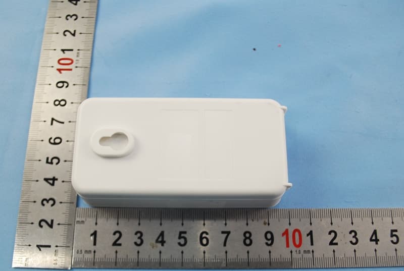
YPG-SE11-01
Aug 19, 2014jumbo wall clock
Equipment Class
DSC - Part 15 Security/Remote Control Transmitter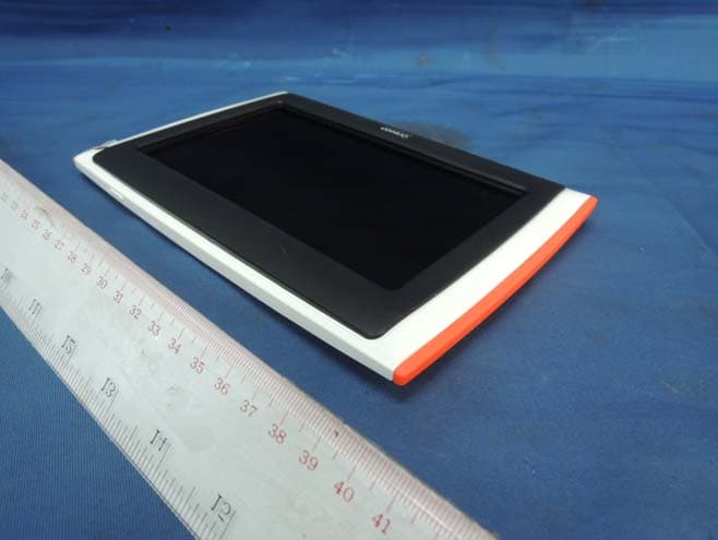
YPG-011813
Aug 29, 2013MEEP X2
Equipment Class
DTS - Digital Transmission System
YPG-WL388
Jul 29, 2013illumi Shine Wake Up Clock
Equipment Class
DTS - Digital Transmission System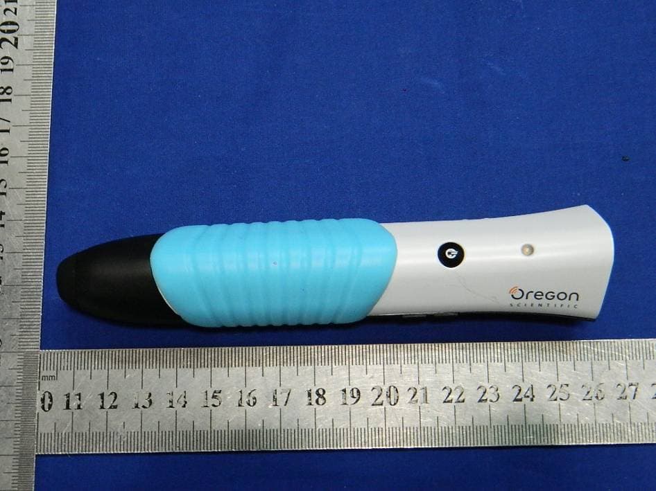
YPG-SG021813
Jul 28, 2013SmartGlobe Horizon (w/Bluetooth Pen), SmartPen
Equipment Class
DTS - Digital Transmission System