YPG-SL109Remote Sensor
Oregon Scientific Global Distribution Limited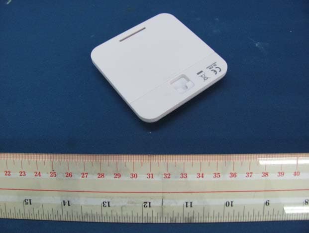
Click to zoom
Application Details
- Equipment Class
- DSC - Part 15 Security/Remote Control Transmitter
- Date of Grant
- Sep 07, 2011
- Application Purpose
- Original Equipment
- Date of Application
- Sep 07, 2011
- Equipment Note
- Remote Sensor
- Frequency Range
- 433.92000000 - 433.92000000
- Country
- Hong Kong
Documents & Files
Document Text
Text extracted from the exhibit documents filed with the FCC. Open a document above to read the original.
Users Manual
SL101 Snap Thermometer Quick Start Guide 1. A. B. C. 2. 3. 4. 5. 6. 7. 8. 9. 10. 11. 12.13.14. 15. 16.17.18.19. FRONT VIEW BACK VIEW Regions: A. B. C. 1. 2. 3. 4. 5. 6. 7. 8. 9. 10. 11. 12. 13. 14. 15. 16. 17. 18. 19. 1. 2. 1. 2. 1. 2. 1. 2. 1. 2. 1. 2. 3. 4. 5. 6. 1. 2. 3. 4. 5. 6. 1. 2. 3. 4. 5. 6. 1. 2. 3. 4. 5. 6. 1. 2. 3. 4. 5. 6. 1. 2. 3. 1. 2. 3. 1. 2. 3. 1. 2. 3. 1. 2. 3. 1. 2. 3. 1. 2. 3. 1. 2. 3. 1. 2. 3. 1. 2. 3. • • • • • • • • • • • • • • • • • • • • • • • • • • • • • • • • • • • • • • • • • • • • • • • • • • • • • • • • • • • • • • • • • • • • • 1. 2. 3. 1. 2. 3. 1. 2. 3. 1. 2. 3. 1. 2. 3. 1. 2. 1. 2. 1. 2. 1. 2. 1. 2. • • • • • Regioni: A. B. C. 1. 2. 3. 4. 5. 6. 7. 8. 9. 10. 11. 12. 13. 14. 15. 16. 17. 18. 19. Zones: A. B. C. 1. 2. 3. 4. 5. 6. 7. 8. 9. 10. 11. 12. 13. 14. 15. 16. 17. 18. 19. Regiones: A. B. C. 1. 2. 3. 4. 5. 6. 7. 8. 9. 10. 11. 12. 13. 14. 15. 16. 17. 18. 19. 1. 2. 3. 4. 5. 6. 1. 2. 3. 4. 5. 6. 1. 2. 3. 4. 5. 6. 1. 2. 3. 4. 5. 6. 1. 2. 3. 4. 5. 6. Bereich: A. B. C. 1. 2. 3. 4. 5. 6. 7. 8. 9. 10. 11. 12. 13. 14. 15. 16. 17. 18. 19. Max / Min temperature Channel Clock and Calendar SNOOZE : activate snooze alarm Ice alert indicator : remote sensor reception indicator and outdoor channel selected : sensor batteries low : main unit batteries low : indicates which reading is displayed (maximum / minimum) Indoor / outdoor temperature ALARM : alarm mode is displayed : alarm is ON Clock / calendar SET CLOCK : enter time setting; confirm and move to next setting SET ALARM : enter alarm setting; confirm alarm setting ALARM ON / OFF : turn alarm on / off + / - : increase / decrease value of the setting; toggle setting options Battery compartment ºC / ºF : select temperature unit ºC / ºF RESET : reset unit to default settings SENSOR : initiate search for sensor DISPLAY : hide or display clock / calendar information Inserire le batterie, rispettando la polarità indicata (+ e -). Premere RESET dopo ogni sostituzione di batteria. Insérez les piles, en respectant les polarités (+ et -). Appuyez sur RESET (REINITIALISER) après chaque changement de pile. Legen Sie die Batterien ein und achten Sie auf die Übereinstimmung der Polaritäten (+ und -). Drücken Sie nach jedem Batteriewechsel auf RESET. Inserte la pila haciendo coincidir la polaridad (+ / -). Pulse RESET cada vez que cambie las pilas. Insert batteries matching the polarity (+ and -). Press RESET after each battery change. TYPE L x W x H Weight Temperature range Signal frequency Power TIPO L x P x H Peso TYPE L x P x H Poids Plage de la température Fréquence du signal Alimentation TYP L x B x H Gewicht Temperaturbereich Signalfrequenz Stromversorgung Rango de temperatura Frecuencia de la señal Alimentación TIPO L x A x H Peso DESCRIPTION 80 x 90 x 83 mm (3.2 x 3.5 x 3.3 in) 120g (4.2 oz) -5 °C to 50 °C ( 23 °F to 122 °F) 433 MHz 2 x UM-4 (AAA) 1.5 V batteries DESCRIZIONE 80 x 90 x 83mm 120g DESCRIPTION 80 x 90 x 83 mm (3,2 x 3,5 x 3,3 pouces) 120 g (4,72 onces) - 5 °C à 50 °C (23 °F à 122 °F) 433 MHz 2 piles UM-4 (AAA) 1,5 V BESCHREIBUNG 80 x 90 x 83 mm 120 g -5 °C bis 50 °C (23 °F bis 122 °F) 433 MHz 2 Batterien UM-4 (AAA) 1,5 V De -5°C a 50°C (De 23°F a 122°F) 433MHz 2 pilas UM-4 (AAA) de 1,5V DESCRIPCIÓN 80 x 90 x 83mm (3,2 x 3,5 x 3,3 pulgadas) 120g (4,2 onzas) If temperature recorded falls between -2 °C to 3 °C (29°F to 37°F), LED indicator will flash and will stop flashing once the temperature is out of this range. The following information is not to be used as contact for support or sales. Please call our customer service number (listed on our website at www.oregonscientific. com), or on the warranty card for this product) for all inquiries instead. We Name: Address: Telephone No.: declare that the product Product No.: Product Name: Manufacturer / Importer: Address: Oregon Scientific, Inc. 19861 SW 95th Ave.,Tualatin, Oregon 97062 USA 1-800-853-8883 SL101 Snap Temperature Oregon Scientific Global Distribution Limited Block C, 9/F, Kaiser Estate, Phase 1, 41 Man Yue St., Hung Hom, Kowloon, Hong Kong Se la temperatura registrata scende tra i -2°C e i 3°C, l’indicatore LED lampeggia e smetterà di lampeggiare quando la temperatura sarà uscita da questa fascia. Si la température enregistrée est inférieure à -2 °C à 3 °C, (29 °F à 37 °F), le voyant LED clignotera. Il s’arrêtera de clignoter une fois la température hors de cette gamme. Wenn die aufgezeichnete Temperatur auf einen Wert zwischen -2 °C und 3 °C (29 °F und 37 °F) abfällt, blinkt der LED-Indikator; er hört auf zu blinken, sobald sich die Temperatur wieder außerhalb dieses Bereichs befindet. Si la temperatura registrada está entre los -2°C y los 3°C (29°F a 37°F), el indicador luminoso parpadeará hasta que la temperatura esté fuera de este intervalo de temperatura. Questo prodotto può funzionare con un numero massimo di 3 sensori contemporaneamente per rilevare la temperatura in diversi punti. Ce produit peut s’accompagner à tout moment de 3 sondes relevant la température en divers endroits. Dieses Produkt kann jederzeit mit bis zu 3 Sendeeinheiten betrieben werden, um Messwerte der Temperatur an unterschiedlichen Standorten zu erfassen. Este producto puede funcionar hasta con 3 sensores al mismo tiempo para capturar los registros de temperatura en varios lugares. This product can work with up to 3 sensors at any one time to capture temperature reading in various locations. Impostazione dell’ora: Pour régler l’horloge: So stellen Sie die Uhr ein: Para ajustar el reloj: To set the clock: Impostazione della sveglia: Régler l’alarme : So stellen Sie den Alarm ein: Para ajustar la alarma: To set the alarm: Selezione dell’unità di misura della temperatura: Spostare la levetta °C / °F. Per alternare le rilevazioni di ciascun sensore esterno: Toccare ripetutamente CHANNEL region (sezione centrale del display) OPPURE Toccare e tenere premuto CHANNEL region per avviare l’alternanza automatica delle rilevazioni dei canali. Per terminare, toccare CHANNEL region. ind…
Text truncated - open the document above for the full version.
External Photos
INTERTEK TESTING SERVICE Report No.: HK11051709-1 FCC ID: YPG-SL109 Equipment Photographs Model: SL109 (External) INTERTEK TESTING SERVICE Report No.: HK11051709-1 FCC ID: YPG-SL109 Equipment Photographs Model: SL109 (External)
ID Label/Location Info
OS | Innovation Product Design DepartmentSNAP SL101_White Version Scale 1:1 White Color Version - Rating Label Silkscreen Artwork RO | 14JUN2011Silkscreen Artwork_007 (US Version) SL101SL109 23.7mm 5.5mm 4.7mm 3.3mm
Internal Photos
INTERTEK TESTING SERVICE Report No.: HK11051709-1 FCC ID: YPG-SL109 Equipment Photographs Model: SL109 (Internal) INTERTEK TESTING SERVICE Report No.: HK11051709-1 FCC ID: YPG-SL109 Equipment Photographs Model: SL109 (Internal) INTERTEK TESTING SERVICE Report No.: HK11051709-1 FCC ID: YPG-SL109 Equipment Photographs Model: SL109 (Internal) INTERTEK TESTING SERVICE Report No.: HK11051709-1 FCC ID: YPG-SL109 Equipment Photographs Model: SL109 (Internal)
Operational Description
FCC ID: YPG-SL109 Technical Description: The brief circuit description is listed as follows: U1 and associated circuit on Main PCB act as MCU. U2 and associated circuit on Main PCB act as Low Battery Detector. X1 and associated circuit on Main PCB act as Clock frequency of MCU. X1 and associated circuit on RF PCB act as Oscillator. Q1 and associated circuit on RF PCB act as Modulator. L2, L3, L5 and associated circuit on RF PCB act as Antenna Matching Circuit. RT and associated circuit on Main PCB act as temperature sensor. Antenna Used: An internal, integral antenna has been used.
Test Report
INTERTEK TESTING SERVICES Report No.: HK11051709-1 Sample No.: 1/1 Code: FCC15C_d / Effective Date: 26 Jan 2010 ( of ) Average Factor Plot - Pursuant to FCC Part 15 Section 15.231(e) Requirement (Pass/Fail)
Test Report
INTERTEK TESTING SERVICES Report No.: HK11051709-1 Sample No.: 1/1 Code: FCC15C_d / Effective Date: 26 Jan 2010 ( of ) Bandwidth Plot - Pursuant to FCC Part 15 Section 15.231(e) Requirement (Pass/Fail)
Test Report
- The test report only allows to be revised within the retention period unless further standard or the requirement was noticed. - This report is for the exclusive use of Intertek's Client and is provided pursuant to the agreement between Intertek and its Client. Intertek's responsibility and liability are limited to the terms and conditions of the agreement. Intertek assumes no liability to any party, other than to the Client in accordance with the agreement, for any loss, expense or damage occasioned by the use of this report. Only the Client is authorized to permit copying or distribution of this report and then only in its entirety. Any use of the Intertek name or one of its marks for the sale or advertisement of the tested material, product or service must first be approved in writing by Intertek. The observations and test results in this report are relevant only to the sample tested. This report by itself does not imply that the material, product, or service is or has ever been under an Intertek certification program. Intertek Testing Services Hong Kong Ltd. 2/F., Garment Centre, 576 Castle Peak Road, Kowloon, Hong Kong. Tel: (852) 2173 8888 Fax: (852) 2785 5487 Website: www.hk.intertek-etlsemko.com TEST REPORT Report No.: HK11051709-1 Oregon Scientific Global Distribution Limited Application For Certification (Original Grant) (FCC ID: YPG-SL109) Transmitter Prepared and Checked by: Approved by: Signed On File Kung Wing Cheong, Steven Engineer Chan Chi Hung, Terry Assistant Supervisor Date: September 08, 2011 INTERTEK TESTING SERVICES Report No.: HK11051709-1 FCC ID: YPG-SL109 i GENERAL INFORMATION Oregon Scientific Global Distribution Limited BRAND NAME: Oregon Scientific, MODEL: SL109 FCC ID: YPG-SL109 Grantee: Oregon Scientific Global Distribution Limited Grantee Address: Block C, 9/F., Kaiser Estate, Phase 1, 41 Man Yue Street, Hung Hom, Kolwoon, Hong Kong. Contact Person: Anthony Cheng Tel: 852-2764 7873 ext. 2832 Fax: N/A e-mail: [email protected] Manufacturer: N/A Manufacturer Address: N/A Brand Name: Oregon Scientific Model: SL109 Type of EUT: Transmitter Description of EUT: Remote Sensor Serial Number: N/A FCC ID: YPG-SL109 Date of Sample Submitted: May 26, 2011 Date of Test: September 05, 2011 Report No.: HK11051709-1 Report Date: September 08, 2011 Environmental Conditions: Temperature: +10 to 40°C Humidity: 10 to 90% INTERTEK TESTING SERVICES Report No.: HK11051709-1 FCC ID: YPG-SL109 ii SUMMARY OF TEST RESULT Oregon Scientific Global Distribution Limited BRAND NAME: Oregon Scientific, MODEL: SL109 FCC ID: YPG-SL109 TEST SPECIFICATION REFERENCE RESULTS Maximum Peak Output Power 15.247(b), (c) / RSS-210 A8.4 N/A Hopping Channel Carrier Frequencies Separation 15.247(e) / RSS-210 A8.1 \ N/A 20dB Bandwidth of the Hopping Channel 15.247(a) / RSS-210 A8.1 N/A Number of Hopping Frequencies 15.247(e) / RSS-210 A8.1 N/A Average Time of Occupancy of Hopping Frequency 15.247(e) / RSS-210 A8.1 N/A Antenna Conducted Spurious Emissions 15.247(d) / RSS-210 A8.5 N/A Radiated Spurious Emissions 15.247(d) / RSS-210 A8.5 N/A RF Exposure Compliance 15.247(i) / RSS-Gen 5.5 N/A Transmitter Power Line Conducted Emissions 15.207 / RSS-Gen 7.2.2 N/A Transmitter Field Strength 15.227 / RSS-310 3.8 N/A Transmitter Field Strength 15.229 / RSS-210 A2.7 N/A Transmitter Field Strength, Bandwidth and Timing Requirement 15.231(a) / RSS-210 A1.1.1 N/A Transmitter Field Strength, Bandwidth and Timing Requirement 15.231(e) / RSS-210 A1.1.5 Pass Transmitter Field Strength and Bandwidth Requirement 15.239 / RSS-210 A2.8 N/A Transmitter Field Strength and Bandwidth Requirement 15.249 / RSS-210 A2.9 N/A Transmitter Field Strength and Bandwidth Requirement 15.235 / RSS-310 3.9 N/A Receiver / Digital Device Radiated Emissions 15.109 / ICES-003 N/A Digital Device Conducted Emissions 15.107 / ICES-003 N/A Note: 1. The EUT uses a permanently attached antenna which, in accordance to section 15.203, is considered sufficient to comply with the pervisions of this section. 2. Pursuant to FCC part 15 Section 15.215(c), the 20 dB bandwidth of the emission was contained within the frequency band designated (mentioned as above) which the EUT operated. The effects, if any, from frequency sweeping, frequency hopping, other modulation techniques and frequency stability over excepted variations in temperature and supply voltage were considered. INTERTEK TESTING SERVICES Report No.: HK11051709-1 FCC ID: YPG-SL109 iii Table of Contents 1.0 General Description....................................................................................... 1 1.1 Product Description ...................................................................................... 1 1.2 Related Submittal(s) Grants .......................................................................... 1 1.3 Test Methodology ......................................................................................... 1 1.4 Test Facility .................................................................................................. 1 2.0 System Test Configuration ............................................................................ 2 2.1 Justification................................................................................................... 2 2.2 EUT Exercising Software .............................................................................. 2 2.3 Special Accessories...................................................................................... 2 2.4 Equipment Modification................................................................................. 2 2.5 Measurement Uncertainty ............................................................................. 2 2.6 Support Equipment List and Description........................................................ 2 3.0 Emission Results ........................................................................................... 3 3.1 Field Strength Calculation ..........................…
Text truncated - open the document above for the full version.
Test Report
INTERTEK TESTING SERVICES Report No.: HK11051709-1 Sample No.: 1/1 Code: FCC15C_d / Effective Date: 26 Jan 2010 ( of ) Timing Plot - Pursuant to FCC Part 15 Section 15.231(e) Requirement (Pass/Fail) INTERTEK TESTING SERVICES Report No.: HK11051709-1 Sample No.: 1/1 Code: FCC15C_d / Effective Date: 26 Jan 2010 ( of ) Timing Plot - Pursuant to FCC Part 15 Section 15.231(e) Requirement (Pass/Fail)
Test Setup Photos
INTERTEK TESTING SERVICE Report No: HK11051709-1 FCC ID: YPG-SL109 Configuration Photographs Worst-Case Radiated Emissions (Front View) Model: SL109 INTERTEK TESTING SERVICE Report No: HK11051709-1 FCC ID: YPG-SL109 Configuration Photographs Worst-Case Radiated Emissions (Back View) Model: SL109
Contact Information
Applicant
Terence Chan(Project Supervisor)
Technical Contact
Intertek Testing Services Hong Kong LtdTerry Chan
[email protected]2173 8503
2/F Garment Centre · Kowloon · Hong Kong
Non-Technical Contact
Intertek Testing Services Hong Kong LtdTerry Chan
[email protected]2173 8503
Test Firm
Intertek Testing Services Hong Kong Ltd.Billy Chow
Technical Specifications
| # | Rule Parts | Frequency Range | Power Output |
|---|---|---|---|
| 1 | 15.231(e) | 433.92 MHz - 433.92 MHz | - |
Other Applications from Oregon Scientific Global Distribution Limited
YPG-SG318
Aug 25, 2014SmartGlobe Infinity
Equipment Class
DXX - Part 15 Low Power Communication Device Transmitter
YPG-SE11-01
Aug 19, 2014jumbo wall clock
Equipment Class
DSC - Part 15 Security/Remote Control Transmitter
YPG-011813
Aug 29, 2013MEEP X2
Equipment Class
DTS - Digital Transmission System
YPG-WL388
Jul 29, 2013illumi Shine Wake Up Clock
Equipment Class
DTS - Digital Transmission System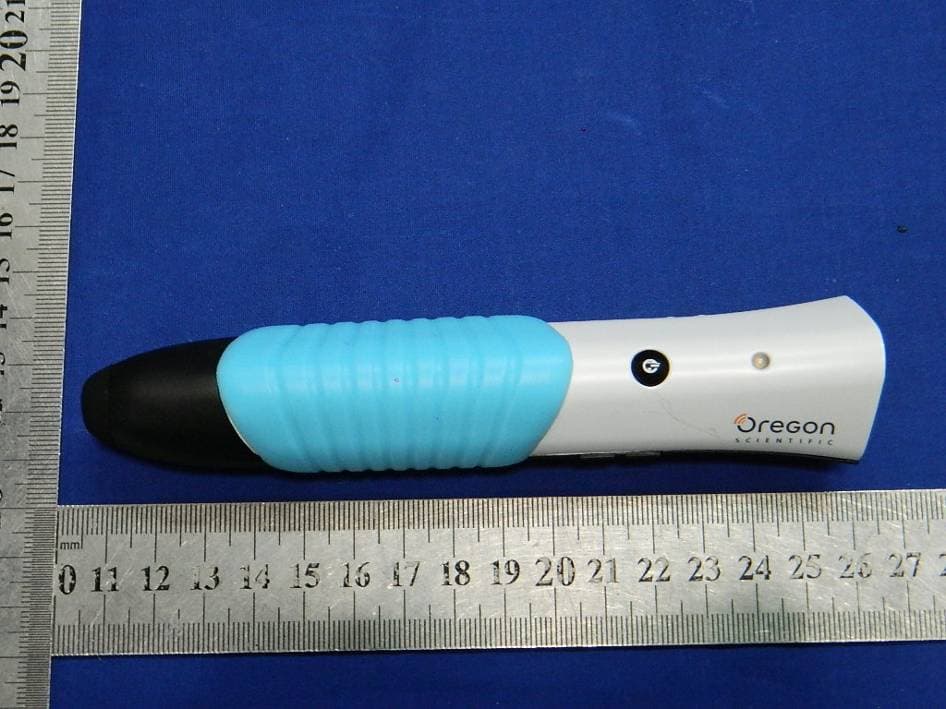
YPG-SG021813
Jul 28, 2013SmartGlobe Horizon (w/Bluetooth Pen), SmartPen
Equipment Class
DTS - Digital Transmission System