YR7AERODRP1AeroDR SYSTEM
KONICA MINOLTA, Inc.
Click to zoom
Application Details
- Equipment Class
- DTS - Digital Transmission System
- Date of Grant
- Oct 26, 2010
- Application Purpose
- Original Equipment
- Date of Application
- Oct 26, 2010
- Equipment Note
- AeroDR SYSTEM
- Frequency Range
- 5745.00000000 - 5825.00000000
- Company
- KONICA MINOLTA, Inc.
- Country
- Japan
Documents & Files
Document Text
Text extracted from the exhibit documents filed with the FCC. Open a document above to read the original.
Users Manual
Introduction Chapter 1 Safety Precautions and Warnings Chapter 2 Product Overview Chapter 3 Basic Operations Chapter 4 Troubleshooting Chapter 5 Maintenance Appendix AeroDR SYSTEM CODE NO. A20H Disclaimer (1)This manual may not be reproduced in whole or in part without the permission of Konica Mi- nolta Medical & Graphic, Inc. (2)The contents of this manual may be subject to change without prior notice. (3)Konica Minolta Medical & Graphic, Inc. is not responsible for any claims made for malfunc- tion or damage caused by installation, relocation, modification, maintenance, and repair made by anyone except Konica Minolta and contractors designated by Konica Minolta. (4)Konica Minolta Medical & Graphic, Inc. is not responsible for any claims made for malfunc- tion or damage to Konica Minolta products, caused by third-party products not installed by Konica Minolta. (5)Konica Minolta Medical & Graphic, Inc. is not responsible for any claims made for malfunc- tion or damage caused by maintenance or repair using maintenance parts other than those specifi ed by Konica Minolta. (6)Konica Minolta Medical & Graphic, Inc. is not responsible for any claims made for malfunc- tion or damage caused by not observing the precautions and operation methods described in the operation manual. (7)Konica Minolta Medical & Graphic, Inc. is not responsible for any claims made for malfunc- tion or damage caused by the environment, such as power source and installation environ- ment, that is described in the Installation Requirement or operation manual, that is not suit- able for the installation requirements of this device. (8)Konica Minolta Medical & Graphic, Inc. is not responsible for any claims for malfunction or damage caused by acts of nature such as fi res, earthquakes, fl oods, or lightning strikes. (9)Konica Minolta Medical & Graphic, Inc. is not responsible for any claims for malfunction or damage caused by using this device for any purpose other than that specifi ed for this device. (10)Diagnostic and treatment action is performed under the responsibility of the physician(s). Konica Minolta Medical & Graphic, Inc. is not responsible for any diagnostic/treatment condi- tions or diagnostic/treatment results. Trademark Company names and product names in this manual are trademarks or registered trademarks of their respective owners. Please note that ©, ® and ™ marks are omitted hereafter. Copyright © 2010 Konica Minolta Medical & Graphic, Inc. All Rights Reserved. 3 Contents Introduction . . . . . . . . . . . . . . . . 5 Application Specifi cation Regarding Usability . . 5 Structure of This Manual . . . . . . . . . . . . . . . . . . 6 Explanation of Terms . . . . . . . . . . . . . . . . . . . . . 6 Structure of Pages . . . . . . . . . . . . . . . . . . . . . . . 7 Chapter 1 Safety Precautions and Warnings . . 9 1.1 Alert Symbols . . . . . . . . . . . . . . . . . . . . . 10 1.2 Warning Notice (Signal Word) . . . . . . . . . 10 1.3 Warning Labels . . . . . . . . . . . . . . . . . . . . 11 1.3.1 AeroDR Detector . . . . . . . . . . . . . . . . 11 1.4 Safety Precautions . . . . . . . . . . . . . . . . . 12 1.4.1 Precautions Before Usage . . . . . . . . . 12 1.4.2 Precautions for Usage . . . . . . . . . . . . 12 1.4.3 Precautions Regarding Electromagnetic Waves . . . . . . . . . . . 13 1.4.4 Precautions Regarding Wireless . . . . 18 1.5 Precautions for Installing, Moving, and Storing . . . . . . . . . . . . . . . . . . . . . . . . . . . 21 1.6 Cautions Regarding Care and Maintenance of the Device . . . . . . . . . . . 21 1.7 Precautions for Parts Replacement and Regular Maintenance . . . . . . . . . . . . . . . 22 Chapter 2 Product Overview . . . . . . . . . . 23 2.1 Overview of This Device . . . . . . . . . . . . . 24 2.1.1 Functions and Features . . . . . . . . . . . 24 2.1.2 System Confi guration Example . . . . . 24 2.1.3 System Connection Example . . . . . . 24 2.2 Component Names and Functions . . . . . 25 2.2.1 AeroDR Detector . . . . . . . . . . . . . . . . 25 2.2.2 AeroDR Interface Unit . . . . . . . . . . . . 26 2.2.3 AeroDR Generator Interface Unit. . . . 27 2.2.4 AeroDR Battery Charger . . . . . . . . . . 28 2.2.5 AeroDR Access Point. . . . . . . . . . . . . 28 2.2.6 AeroDR UF Cable . . . . . . . . . . . . . . . 29 2.2.7 AeroDR I/F Cable. . . . . . . . . . . . . . . . 29 Chapter 3 Basic Operations . . . . . . . . . . . 31 3.1 Startup and Shutdown . . . . . . . . . . . . . . . 32 3.1.1 Power ON . . . . . . . . . . . . . . . . . . . . . 32 3.1.2 Power OFF. . . . . . . . . . . . . . . . . . . . . 33 3.2 Operation of AeroDR Detector. . . . . . . . . 34 3.2.1 Exposure . . . . . . . . . . . . . . . . . . . . . . 34 3.2.2 AeroDR Detector Orientation . . . . . . . 34 3.2.3 Precautions for Exposure. . . . . . . . . . 34 3.3 Charging . . . . . . . . . . . . . . . . . . . . . . . . . 35 3.3.1 Using the AeroDR Battery Charger . . 35 3.3.2 Using the AeroDR I/F Cable. . . . . . . . 35 3.3.3 Charging Time Guide . . . . . . . . . . . . . 36 3.3.4 AeroDR Detector Charging Display . . 36 3.4 Selection and Registration of AeroDR Detector . . . . . . . . . . . . . . . . . . . . . . . . . . 37 3.4.1 Registering the AeroDR Detector. . . . 37 3.4.2 Selecting the AeroDR Detector . . . . . 37 3.5 Gain Calibration. . . . . . . . . . . . . . . . . . . . 38 3.6 Status Display . . . . . . . . . . . . . . . . . . . . . 39 3.6.1 AeroDR Detector . . . . . . . . . . . . . . . . 39 3.6.2 AeroDR Interface Unit . . . . . . . . . . . . 40 3.6.3 AeroDR Generator Interface Unit. . . . 41 3.6.4 AeroDR Battery Charger . . . . . . . . . . 42 Chapter 4 Troubleshooting . . . . . . . . . . . 43 4.1 Error Display and Solutions . . . . . . . . . . . 44 4.2 Action to Be Taken When AeroDR Detector Is Malfunctioning . . . . . . . . . . . . 46 4.3 Fixing Problems. . . . . . . . . . . . . . . . . . . . 46 4.3.1 Phenomena or Conditions That Could Be Malfunctions . . . . . . . . . . . . . . . . . 46 4.3.2 Conditions That Are Not Malfunctions (Corrective …
Text truncated - open the document above for the full version.
Cover Letter(s)
Subject: Letter of Model name variation Dear Underwriters Laboratories, This document confirms that KONICA MINOLTA MEDICAL & GRAPHIC, INC. was advised that the following items need to be provided to the test report. This EUT AeroDR SYSTEM is portable FPD, and it applies to the X-Ray image information reading system for the medical Digital Radiography. The AeroDR SYSTEM have two model name for the High quality image and standard quality image and assigned as follows. Model Name AeroDR P-11: High image Quality AeroDR P-12: Standard image Quality Sincerely yours, KONICA MINOLTA MEDICAL & GRAPHIC, INC.
External Photos
Outline Photograph 460.2mm 384.2mm 15.9mm
ID Label/Location Info
ID Label Location 460.2mm 384.2mm 15.9mm ID Label is located on this surface.
ID Label/Location Info
KONICAMINOLTA Medical & Graphic Inc. ID Label for Overseas (without Japan) FCC ID : YR7AERODRP1IC : 1048H-AERODRP1 This device complies with Part 15 of FCC Rules and RSS-Gen of IC Rules. Operation is subject to the following twoconditions: (1) this device may not cause interference, and (2) this device must accept any interference, includinginterference that may cause undesired operation of this device. This Class A digital apparatus complies with Canadian ICES-003.CMIIT ID: XXXXYZNNNN KONICA MINOLTA MEDICAL & GRAPHIC INC.Made in Japan 1 Sakura-machi, Hino-shi, Tokyo 191-8511 Japan XXXXXXXX 해당무선설비는운용중전파혼신가능성이있음 Product Name: AeroDR SYSTEMMODEL: AeroDR P-11DATE:Serial No.:
ID Label/Location Info
KONICAMINOLTA Medical & Graphic Inc. ID Label for Overseas (without Japan) FCC ID : YR7AERODRP1IC : 1048H-AERODRP1 This device complies with Part 15 of FCC Rules and RSS-Gen of IC Rules. Operation is subject to the following twoconditions: (1) this device may not cause interference, and (2) this device must accept any interference, includinginterference that may cause undesired operation of this device. This Class A digital apparatus complies with Canadian ICES-003.CMIIT ID: XXXXYZNNNN KONICA MINOLTA MEDICAL & GRAPHIC INC.Made in Japan 1 Sakura-machi, Hino-shi, Tokyo 191-8511 Japan XXXXXXXX 해당무선설비는운용중전파혼신가능성이있음 Product Name: AeroDR SYSTEMMODEL: AeroDR P-12DATE:Serial No.:
Internal Photos
JRC Confidential 1/2 WLAN Module CMN-751A Photographs JRC Confidential 2/2
RF Exposure Info
Test report No. : 30DE0169-HO-01-A-R1 Page : 2 of 82 FCC ID : YR7AERODRP1 Issued date : September 16, 2010 Revised date : October 26, 2010 UL Japan, Inc. Head Office EMC Lab. 4383-326 Asama-cho, Ise-shi, Mie-ken 516-0021 JAPAN Telephone : +81 596 24 8116 Facsimile : +81 596 24 8124 CONTENTS PAGE SECTION 1: Customer information ..................................................................................................... 3 SECTION 2: Equipment under test (E.U.T.)........................................................................................ 3 2.1 Identification of E.U.T................................................................................................ 3 2.2 Product Description .................................................................................................... 3 SECTION 3 : Test standard information.............................................................................................. 4 3.1 Requirements for compliance testing defined by the FCC................................................... 4 3.2 Procedure and result................................................................................................... 5 3.3 Exposure limit........................................................................................................... 5 3.4 Test Location............................................................................................................ 6 3.5 Confirmation before SAR testing.................................................................................. 6 3.6 Confirmation after SAR testing..................................................................................... 8 3.7 Measurement procedure.............................................................................................. 9 3.8 Test setup of EUT...................................................................................................... 9 SECTION 4 : Operation of E.U.T. during testing .............................................................................. 10 4.1 Operating modes for SAR testing................................................................................ 10 SECTION 5 : Test surrounding ........................................................................................................... 11 5.1 Measurement uncertainty........................................................................................... 11 SECTION 6 : Confirmation before testing ......................................................................................... 12 6.1 Correlation of Output Power between EMC and SAR tests............................................... 12 6.2 Peak and Average power for SAR testing...................................................................... 14 SECTION 7 : Measurement results ..................................................................................................... 16 7.1 BODY SAR 5180-5320MHz...................................................................................... 16 7.2 BODY SAR 5745-5825MHz...................................................................................... 17 APPENDIX 1 : Photographs of test setup .........................................................................................................................18 1. Photograph of EUT ...................................................................................................................................... 19 2. Position of antenna....................................................................................................................................... 19 3. Photograph of test setup.............................................................................................................................. 20 APPENDIX 2 : SAR Measurement data ...........................................................................................................................22 1. Evaluation procedure................................................................................................................................... 23 2. Measurement data (Body SAR 5180-5320MHz band).......................................................................... 24 3. Measurement data (Body SAR 5745-5825MHz band) .......................................................................... 35 APPENDIX 3 : Test instruments .......................................................................................................................................44 1. Equipment used ............................................................................................................................................. 45 2. Dosimetry assessment setup....................................................................................................................... 46 3. Configuration and peripherals.................................................................................................................... 47 4. System components ..................................................................................................................................... 48 5. Test system specifications .......................................................................................................................... 50 6. Simulated Tissues Composition (5GHz).................................................................................................. 51 7. Simulated Tissue Liquid Parameter confirmation (5GHz).................................................................... 51 8. System validation data(5GHz) ................................................................................................................... 53 9. Validation uncertainty................................................................................................................................. 54 10. Validation Measurement data..............................................................…
Text truncated - open the document above for the full version.
RF Exposure Info
Test report No. : 30DE0169-HO-01-A-R1 Page : 22 of 82 FCC ID : YR7AERODRP1 Issued date : September 16, 2010 Revised date : October 26, 2010 UL Japan, Inc. Head Office EMC Lab. 4383-326 Asama-cho, Ise-shi, Mie-ken 516-0021 JAPAN Telephone : +81 596 24 8116 Facsimile : +81 596 24 8124 APPENDIX 2 : SAR Measurement data Test report No. : 30DE0169-HO-01-A-R1 Page : 23 of 82 FCC ID : YR7AERODRP1 Issued date : September 16, 2010 Revised date : October 26, 2010 UL Japan, Inc. Head Office EMC Lab. 4383-326 Asama-cho, Ise-shi, Mie-ken 516-0021 JAPAN Telephone : +81 596 24 8116 Facsimile : +81 596 24 8124 1. Evaluation procedure The evaluation was performed with the following procedure: Step 1: Measurement of the E-field at a fixed location above the ear point or central position of flat phantom was used as a reference value for assessing the power drop. Step 2: The SAR distribution at the exposed side of head or body position was measured at a distance of each device from the inner surface of the shell. The area covered the entire dimension of the antenna of EUT and the horizontal grid spacing was 15 mm x 15 mm . Based on these data, the area of the maximum absorption was determined by spline interpolation. Step 3: Around this point found in the Step 2 (area scan), a volume of 28mm x 28mm x 22.5mm was assessed by measuring 8 x 8 x 10 points for IEEE802.11a(5G). And for any secondary peaks found in the Step2 which are within 2dB of maximum peak (level more than ambient noise (> 0.012 W/kg)) and not with this Step3 (Zoom scan) is repeated. On the basis of this data set, the spatial peak SAR value was evaluated under the following procedure: (1). The data at the surface were extrapolated, since the center of the dipoles is 1mm away from the tip of the probe and the distance between the surface and the lowest measuring point is 1mm. Therefore minimum distance of probe sensor from surface was set to the 2mm. The extrapolation was based on a least square algorithm [4]. A polynomial of the fourth order was calculated through the points in z-axes. This polynomial was then used to evaluate the points between the surface and the probe tip. (2). The maximum interpolated value was searched with a straightforward algorithm. Around this maximum the SAR values averaged over the spatial volumes (1 g or 10 g) were computed by the 3D-Spline interpolation algorithm. The 3D-Spline is composed of three one-dimensional splines with the “Not a knot"-condition (in x, y and z-directions) [4], [5]. The volume was integrated with the trapezoidal-algorithm. One thousand points (10 x 10 x 10) were interpolated to calculate the average. (3). All neighboring volumes were evaluated until no neighboring volume with a higher average value was found. Step 4: Re-measurement of the E-field at the same location as in Step 1. Test report No. : 30DE0169-HO-01-A-R1 Page : 24 of 82 FCC ID : YR7AERODRP1 Issued date : September 16, 2010 Revised date : October 26, 2010 UL Japan, Inc. Head Office EMC Lab. 4383-326 Asama-cho, Ise-shi, Mie-ken 516-0021 JAPAN Telephone : +81 596 24 8116 Facsimile : +81 596 24 8124 2. Measurement data (Body SAR 5180-5320MHz band) AeroDR P-11/Body/Main antenna/Front/11a BPSK 6Mbps/5260MHz Duty Cycle: 1:1 Medium: M5200 Medium parameters used: f = 5300 MHz; σ = 5.65 mho/m; ε r = 46.6; ρ = 1000 kg/m 3 Phantom section: Flat Section DASY4 Configuration: - Probe: EX3DV3 - SN3507; ConvF(4.22, 4.22, 4.22); Calibrated: 2010/02/19 - Sensor-Surface: 2mm (Mechanical Surface Detection) - Phantom: Flat Phantom ELI4.0 - Measurement SW: DASY4, V4.7 Build 80; Postprocessing SW: SEMCAD, V1.8 Build 186 Area Scan (101x201x1): Measurement grid: dx=10mm, dy=10mm Maximum value of SAR (interpolated) = 1.67 mW/g Zoom Scan (8x8x10)/Cube 0: Measurement grid: dx=4mm, dy=4mm, dz=2.5mm Reference Value = 0.730 V/m; Power Drift = -0.128 dB Peak SAR (extrapolated) = 2.87 W/kg SAR(1 g) = 0.709 mW/g; SAR(10 g) = 0.171 mW/g Maximum value of SAR (measured) = 1.37 mW/g Test Date = 06/18/10 Ambient Temperature = 24.0 degree.C. Liquid Temperature = Before 23.0 degree.C. , After 23.0 degree.C. Test report No. : 30DE0169-HO-01-A-R1 Page : 25 of 82 FCC ID : YR7AERODRP1 Issued date : September 16, 2010 Revised date : October 26, 2010 UL Japan, Inc. Head Office EMC Lab. 4383-326 Asama-cho, Ise-shi, Mie-ken 516-0021 JAPAN Telephone : +81 596 24 8116 Facsimile : +81 596 24 8124 AeroDR P-11/Body/Main antenna/Front/11a 16QAM 24Mbps /5260MHz Duty Cycle: 1:1 Medium: M5200 Medium parameters used: f = 5300 MHz; σ = 5.65 mho/m; ε r = 46.6; ρ = 1000 kg/m 3 Phantom section: Flat Section DASY4 Configuration: - Probe: EX3DV3 - SN3507; ConvF(4.22, 4.22, 4.22); Calibrated: 2010/02/19 - Sensor-Surface: 2mm (Mechanical Surface Detection) - Phantom: Flat Phantom ELI4.0 - Measurement SW: DASY4, V4.7 Build 80; Postprocessing SW: SEMCAD, V1.8 Build 186 Area Scan (101x201x1): Measurement grid: dx=10mm, dy=10mm Maximum value of SAR (interpolated) = 1.86 mW/g Zoom Scan (8x8x10)/Cube 0: Measurement grid: dx=4mm, dy=4mm, dz=2.5mm Reference Value = 0.798 V/m; Power Drift = 0.121 dB Peak SAR (extrapolated) = 3.25 W/kg SAR(1 g) = 0.795 mW/g; SAR(10 g) = 0.192 mW/g Maximum value of SAR (measured) = 1.56 mW/g Test Date = 06/18/10 Ambient Temperature = 24.0 degree.C. Liquid Temperature = Before 23.0 degree.C. , After 23.0 degree.C. Test report No. : 30DE0169-HO-01-A-R1 Page : 26 of 82 FCC ID : YR7AERODRP1 Issued date : September 16, 2010 Revised date : October 26, 2010 UL Japan, Inc. Head Office EMC Lab. 4383-326 Asama-cho, Ise-shi, Mie-ken 516-0021 JAPAN Telephone : +81 596 24 8116 Facsimile : +81 596 24 8124 AeroDR P-11/Body/Main antenna/Front/11a 16QAM 24Mbps /5180MHz Duty Cycle: 1:1 Medium: M5200 Medium parameters used: f = 5200 MHz; σ = 5.47 mho/m; ε r = 46.6; ρ = 1000 kg/m 3 Phantom section: Flat Section DASY4 Configuration: - Probe: EX3DV3 - SN3507; ConvF(4.41, 4.41, 4.41); Calibrated: 2010/02/19 - Sensor-Surface: 2mm (Mechanical Surface Detection) - Phantom: Flat Phantom ELI4.0 - M…
Text truncated - open the document above for the full version.
RF Exposure Info
Test report No. : 30DE0169-HO-01-A-R1 Page : 44 of 82 FCC ID : YR7AERODRP1 Issued date : September 16, 2010 Revised date : October 26, 2010 UL Japan, Inc. Head Office EMC Lab. 4383-326 Asama-cho, Ise-shi, Mie-ken 516-0021 JAPAN Telephone : +81 596 24 8116 Facsimile : +81 596 24 8124 APPENDIX 3 : Test instruments Test report No. : 30DE0169-HO-01-A-R1 Page : 45 of 82 FCC ID : YR7AERODRP1 Issued date : September 16, 2010 Revised date : October 26, 2010 UL Japan, Inc. Head Office EMC Lab. 4383-326 Asama-cho, Ise-shi, Mie-ken 516-0021 JAPAN Telephone : +81 596 24 8116 Facsimile : +81 596 24 8124 1. Equipment used Control No. Instrument Manufacturer Model No Serial No Test Item Calibration Date * Interval(month) MAT-22 Attenuator(10dB) DC- 18GHz Orient Microwave BX10-0476-00 - Power Measurement 2010/03/01* 12 MPM-09 Power Meter Anritsu ML2495A 6K00003348 Power Measurement 2009/09/09 * 12 MPSE-12 Power sensor Anritsu MA2411B 011598 Power Measurement 2009/09/09 * 12 MPM-01 Power Meter Agilent E4417A GB41290639 SAR 2010/02/16 * 12 MPSE-01 Power Sensor Agilent E9300B US40010300 SAR 2010/02/11 * 12 MPSE-03 Power sensor Agilent E9327A US40440576 SAR 2010/02/19 * 12 MAT-15 Attenuator(30dB) Agilent 8498A US40010300 SAR 2010/02/24 * 12 MSG-10 Signal Generator Agilent N5181A MY47421098 SAR 2009/06/30 * 24 MRFA-08 Pre Amplifier TSJ TCBP0206 - SAR 2010/03/19 * 12 MHDC-12 Dual Directional Coupler Hewlett Packard 772D 2839A0016 SAR Pre Check MNA-01 Network Analyzer Agilent/HP E8358A US41080381 SAR 2009/08/28 * 12 MDPK-01 Dielectric probe kit Agilent 85070D SAR Pre Check MNCK-01 Type N Calibration Kit Agilent 85032F MY41495257 SAR 2009/08/28 * 12 MPB-03 Dosimetric E-Field Probe Schmid&Partner Engineering AG EX3DV3 3507 SAR 2010/02/19 * 12 MDAE-01 Data Acquisition Electronics Schmid&Partner Engineering AG DAE3 V1 509 SAR 2009/07/08* 12 COTS-MSTW-16 DASY4 Schmid&Partner Engineering AG DASY4 V4.7 Build71 - SAR - COTS-MSTW-17 S-Parameter Network Analyzer Agilent - - SAR - MDA-08 Dipole Antenna Schmid&Partner Engineering AG D5GHzV2 1020 SAR 2009/08/19 * 24 MPF-02 2mmOval Flat Phantom ERI 4.0 Schmid&Partner Engineering AG QD VA 001B (ERI4.0) 1045 SAR - MOS-05 Thermo-Hygrometer Custom CTH-190 810201 SAR 2010/04/21 * 12 MOS-10 Digtal thermometer HANNA Checktemp-2 MOS-10 SAR 2010/02/05* 12 MBM-13 Barometer Sunoh SBR121 837 SAR 2008/03/14 * 36 Muscle 5800MHz Daily check Target value ± 5 to 10% SAR room Daily check Ambient Noise<0.012W/kg The expiration date of the calibration is the end of the expired month. As for some calibrations performed after the tested dates, those test equipment have been controlled by means of an unbroken chains of calibrations. Test report No. : 30DE0169-HO-01-A-R1 Page : 46 of 82 FCC ID : YR7AERODRP1 Issued date : September 16, 2010 Revised date : October 26, 2010 UL Japan, Inc. Head Office EMC Lab. 4383-326 Asama-cho, Ise-shi, Mie-ken 516-0021 JAPAN Telephone : +81 596 24 8116 Facsimile : +81 596 24 8124 2. Dosimetry assessment setup These measurements were performed with the automated near-field scanning system DASY4 from Schmid & Partner Engineering AG (SPEAG). The system is based on a high precision robot (working range greater than 0.9 m), which positions the probes with a positional repeatability of better than +/- 0.02 mm. Special E- and H-field probes have been developed for measurements close to material discontinuity, the sensors of which are directly loaded with a Schottky diode and connected via highly resistive lines to the data acquisition unit. The SAR measurements were conducted with the dosimetry probe EX3DV3, SN: 3507(manufactured by SPEAG), designed in the classical triangular configuration and optimized for dosimetric evaluation. The probe has been calibrated according to the procedure described in [2] with accuracy of better than +/-10%. The spherical isotropy was evaluated with the procedure described in [3] and found to be better than +/-0.25 dB. The phantom used was the SAM Twin Phantom as described in FCC supplement C, IEEE P1528 and CENELEC EN50361. Test report No. : 30DE0169-HO-01-A-R1 Page : 47 of 82 FCC ID : YR7AERODRP1 Issued date : September 16, 2010 Revised date : October 26, 2010 UL Japan, Inc. Head Office EMC Lab. 4383-326 Asama-cho, Ise-shi, Mie-ken 516-0021 JAPAN Telephone : +81 596 24 8116 Facsimile : +81 596 24 8124 3. Configuration and peripherals The DASY4 system for performing compliance tests consist of the following items: 1. A standard high precision 6-axis robot (Stäubli RX family) with controller and software. An arm extension for accommodating the data acquisition electronics (DAE). 2. A dosimetric probe, i.e., an isotropic E-field probe optimized and calibrated for usage in tissue simulating liquid. The probe is equipped with an optical surface detector system. 3. A data acquisition electronic (DAE), which performs the signal amplification, signal multiplexing, AD-conversion, offset measurements, mechanical surface detection, collision detection, etc. The unit is battery powered with standard or rechargeable batteries. The signal is optically transmitted to the EOC. 4. The Electro-optical converter (EOC) performs the conversion between optical and electrical of the signals for the digital communication to the DAE and for the analog signal from the optical surface detection. The EOC is connected to the measurement server. 5. The function of the measurement server is to perform the time critical tasks such as signal filtering, control of the robot operation and fast movement interrupts. 6. A probe alignment unit which improves the (absolute) accuracy of the probe positioning. 7. A computer operating Windows 2000. 8. DASY4 software. 9. Remote control with teaches pendant and additional circuitry for robot safety such as warning lamps, etc. 10. The 2mm Flat phantom ERI4.0 11. The device holder for handheld mobile phones. 12. Tissue simulating liquid mixed according to the given recipes. 13. Validation dipole kits allowing to validate the proper fu…
Text truncated - open the document above for the full version.
Test Report
Test report No. : 30DE0169-SH-01 -A Page : 2 of 30 Issued date : September 27, 2010 FCC ID : YR7AERODRP1 UL Japan, Inc. Shonan EMC Lab. 1-22-3 Megumigaoka, Hiratsuka-shi, Kanagawa-ken, 259-1220 JAPAN Telephone: +81 463 50 6400 Facsimile: +81 463 50 6401 Table of Contents Page 1 Applicant Information 3 2 Equipment under test (E.U.T.) 3 3 Test specification, procedures and results 4 4 System test configuration 7 5 6dB bandwidth & Occupied bandwidth (99%) 8 6 Maximum peak output power 8 7 Out of band emissions (Antenna port conducted) 8 8 Out of band emissions (Radiated) 9 9 Peak power density 10 Contents of Appendixes 11 APPENDIX 1: Photographs of test setup 12 APPENDIX 2: Test data 14 APPENDIX 3: Test instruments 30 Test report No. : 30DE0169-SH-01 -A Page : 3 of 30 Issued date : September 27, 2010 FCC ID : YR7AERODRP1 UL Japan, Inc. Shonan EMC Lab. 1-22-3 Megumigaoka, Hiratsuka-shi, Kanagawa-ken, 259-1220 JAPAN Telephone: +81 463 50 6400 Facsimile: +81 463 50 6401 1 Applicant information Company Name : KONICA MINOLTA MEDICAL & GRAPHIC, INC. Address : 1 Sakura-Machi, Hino-Shi, Tokyo, 191-8511 Japan Telephone Number : +81-42-589-8429 Facsimile Number : +81-42-589-8053 Contact Person : Masayoshi Inoue 2 Equipment under test (E.U.T.) 2.1 Identification of E.U.T. Type of Equipment : AeroDR SYSTEM Model No. : AeroDR P-11 Serial No. : 11 Rating : DC15V Country of Mass-production : Japan Condition of EUT : Engineering prototype (Not for Sale: This sample is equivalent to mass-produced items.) Modification of EUT : No modification by the test lab. Receipt Date of Sample : May 25, 2010 2.2 Product description Model: AeroDR P-11 (referred to as the EUT in this report) is a AeroDR SYSTEM. The similar models of the EUT are as follows AeroDR P-11:High image Quality AeroDR P-12:Standard image Quality Equipment type : Transceiver Frequency of operation : 5180-5320MHz *1 5745-5825MHz Clock frequency : 32.768kHz, 26MHz Bandwidth & channel spacing : Bandwidth : 18MHz Channel spacing : 20MHz Type of modulation : 11a : OFDM Antenna type : Planar Inverted F Antenna Antenna gain with cable loss : +3.78dBi Antenna connector type : U.FL ITU code : D1D, G1D Operation temperature range : +10 to +30 deg.C. *1) Refer to 30DE0169-SH-01-B, FCC part 15E (FCC15.407) report.. FCC Part15.31 (e) This EUT provides stable voltage (DC3.3V) constantly to RF part regardless of input voltage. Therefore, this EUT complies with the requirement. FCC Part15.203 Antenna requirement It is impossible for end users to replace the antenna, because the antenna is mounted inside of the EUT. Therefore, the equipment complies with the antenna requirement of Section 15.203. Test report No. : 30DE0169-SH-01 -A Page : 4 of 30 Issued date : September 27, 2010 FCC ID : YR7AERODRP1 UL Japan, Inc. Shonan EMC Lab. 1-22-3 Megumigaoka, Hiratsuka-shi, Kanagawa-ken, 259-1220 JAPAN Telephone: +81 463 50 6400 Facsimile: +81 463 50 6401 3 Test specification, procedures and results 3.1 Test specification Test specification : FCC Part 15 Subpart C: 2010, final revised on January 22, 2010 and effective March 1, 2010 Title : FCC 47CFR Part15 Radio Frequency Device Subpart C Intentional Radiators Section 15.207 Conducted limits Section 15.209 Radiated emission limits, general requirements Section 15.247 Operation within the bands 902-928MHz, 2400-2483.5MHz, and 5725-5850MHz 3.2 Procedures & Results ItemTest Procedure SpecificationRemarksDeviationWorst Margin Results Conducted Emission ANSI C63.4:2003 7. AC powerline conducted emission measurements FCC 15.207 - N/A *1 N/A N/A 6dB Bandwidth "Guidance on Measurement for Digital Transmission Systems Section 15.247" & ANSI C63.4:2003 13. Measurement of intentional radiators FCC 15.247 (a)(2) & 15.209 ConductedN/A Complied Maximum Peak Output Power "Guidance on Measurement for Digital Transmission Syst…
Text truncated - open the document above for the full version.
Contact Information
Applicant
Ken Nagami(Assistant Manager)
Technical Contact
UL Japan, Inc.Tatsuya Arai
[email protected]81-463-50-6400
1-22-3 Megumigaoka, Hiratsuka-shi · Kanagawa-ken · Japan
Test Firm
UL Japan, Inc. Shonan EMC EMC Lab.Tetsuya Hashimoto
Technical Specifications
| # | Rule Parts | Frequency Range | Power Output |
|---|---|---|---|
| 1 | 15C | 5.75 GHz - 5.83 GHz | 74.30 mW |
Other Applications from KONICA MINOLTA, Inc.
YR7SKR3000P9
Jul 07, 2024SKR 3000
Equipment Class
NII - Unlicensed National Information Infrastructure TX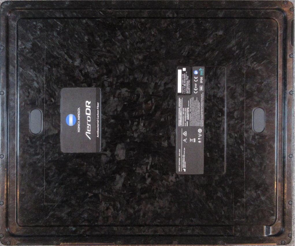
YR7SKR3000P8
Feb 23, 2022SKR 3000
Equipment Class
DTS - Digital Transmission System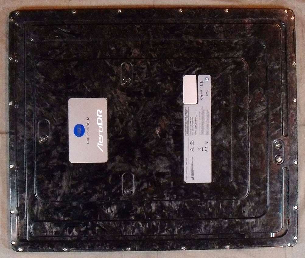
YR7SKR3000P7
May 30, 2021SKR 3000
Equipment Class
NII - Unlicensed National Information Infrastructure TX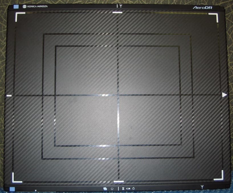
YR7AERODRP5
Sep 03, 2014AeroDR SYSTEM 2
Equipment Class
NII - Unlicensed National Information Infrastructure TX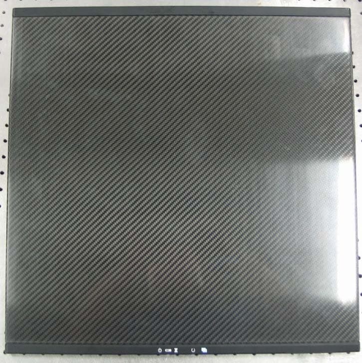
YR7AERODRP2
Dec 27, 2011AeroDR SYSTEM
Equipment Class
DTS - Digital Transmission System