YR7AERODRP5AeroDR SYSTEM 2
KONICA MINOLTA, Inc.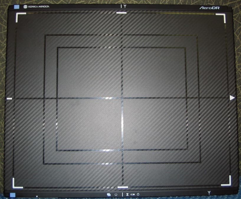
Click to zoom
Application Details
- Equipment Class
- NII - Unlicensed National Information Infrastructure TX
- Date of Grant
- Sep 03, 2014
- Application Purpose
- Original Equipment
- Date of Application
- Sep 03, 2014
- Equipment Note
- AeroDR SYSTEM 2
- Frequency Range
- 5745.00000000 - 5825.00000000
- Company
- KONICA MINOLTA, Inc.
- Country
- Japan
Documents & Files
Document Text
Text extracted from the exhibit documents filed with the FCC. Open a document above to read the original.
Users Manual
0197 Operation Manual EN01 A45YBD01EN01 20131220CT DIRECTDIGITIZERAeroDRSYSTEM2 OperationManual SYSTEM 2 DIRECT DIGITIZER 3 Contents Chapter 3 General Operations . . . . . . . . . 45 3.1 Startup and shutdown . . . . . . . . . . . . . . . 46 3.1.1 Startup sequence of this device .. . . .46 3.1.2 Startup of this device . . . . . . . . . . . . .46 3.1.3 Shutdown sequence of this device . .48 3.1.4 Shutdown of this device .. . . . . . . . . .49 3.2 Operation of AeroDR Detector. .. . . . . . .51 3.2.1 Exposure . .. . . . . . . . . . . . . . . . . . . .51 3.2.2 AeroDR Detector orientation . .. . . . .52 3.2.3 Precautions for exposure .. . . . . . . . .52 3.3 Charging of AeroDR Detector . . . . . . . . .56 3.3.1 Charging with AeroDR Battery Charger . .. . . . . . . . . . . . . . .56 3.3.2 Charging with AeroDR Battery Charger2 . .. . . . . . . . . . . . . . . . . . . .57 3.3.3 Charging with the wired cable . .. . . .59 3.3.4 Charging time guide .. . . . . . . . . . . . .59 3.3.5 AeroDR Detector charging display. . . 59 3.4 Registration and selection of the AeroDR Detector. . . . . . . . . . . . . . . . . . . . . . . . . . 60 3.4.1 Registration with AeroDR Battery Charger . .. . . . . . . . . . . . . . . . . . . . .60 3.4.2 Registration with AeroDR Battery Charger2 . .. . . . . . . . . . . . . . . . . . . .60 3.4.3 Registration with the wired cable .. . .61 3.4.4 Selection of the AeroDR Detector . ..61 3.4.5 Manual selection of the AeroDR Detector . . . . . . . . . . . . . . . . . . . . . . .62 3.5 Calibration. .. . . . . . . . . . . . . . . . . . . . . .63 3.6 Position to affix AeroDR D etector identification label .. . . . . . . . . . . . . . . . .64 Chapter 4 Status (LED) Display . . . . . . . . 65 4.1 LED display of respective devices. .. . . .66 4.1.1 AeroDR Detector . .. . . . . . . . . . . . . .66 4.1.2 AeroDR Interface Unit . . . . . . . . . . . . 67 4.1.3 AeroDR Interface Unit2 . .. . . . . . . . .68 4.1.4 AeroDR Generator Interface Unit . . . . 69 4.1.5 AeroDR Battery Charger . . . . . . . . . . 70 4.1.6 AeroDR Battery Charger2 . . . . . . . . . 71 4.1.7 Access Point . .. . . . . . . . . . . . . . . . .72 Chapter 5 Troubleshooting . . . . . . . . . . . 73 5.1 Support flow during trouble . . . . . . . . . . . 74 5.2 Various problems and countermeasures. .76 5.2.1 AeroDR Detector . .. . . . . . . . . . . . . .76 5.2.2 AeroDR Interface Unit . . . . . . . . . . . . 78 Introduction . . . . . . . . . . . . . . . . 5 Introduction. .. . . . . . . . . . . . . . . . . . . . . . . . . . . .6 Indications for Use . .. . . . . . . . . . . . . . . . . . . . .6 Summary of usability specifications (for IEC/EN 60601-1-6, IEC/EN 62366) .. . . . . .7 Disclaimer. . . . . . . . . . . . . . . . . . . . . . . . . . . . . . 7 Trademark . .. . . . . . . . . . . . . . . . . . . . . . . . . . .8 AeroDR SYSTEM name correspondence table ..8 Term description .. . . . . . . . . . . . . . . . . . . . . . . .8 Structure of pages . .. . . . . . . . . . . . . . . . . . . . .9 Chapter 1 Safety Precautions & Warnings . . 11 1.1 Symbols relating to safety. .. . . . . . . . . .12 1.1.1 Safety alert symbol . .. . . . . . . . . . . .12 1.1.2 Warning notice (signal words) . .. . . .12 1.1.3 Description of graphic symbols . .. . .12 1.2 Warning labels. .. . . . . . . . . . . . . . . . . . .13 1.2.1 AeroDR Detector . .. . . . . . . . . . . . . .13 1.2.2 AeroDR Battery Charger . .. . . . . . . .14 1.2.3 AeroDR Battery Charger2 . .. . . . . . .14 1.3 Safety precautions. .. . . . . . . . . . . . . . . .15 1.3.1 Precautions before usage . .. . . . . . .15 1.3.2 Precautions for usage . .. . . . . . . . . .15 1.3.3 Precautions regarding electromagnetic waves . .. . . . . . . . .18 1.3.4 Precautions regarding wireless communication .. . . . . . . . . . . . . . . . .23 1.3.5 Precautions for installing, moving, and storing .. . . . . . . . . . . . . . . . . . . .25 1.3.6 P recautions regarding maintenance ..26 1.3.7 Precautions on service life .. . . . . . . .27 1.3.8 Pediatric patients’ use; . . . . . . . . . . . .27 1.4 R&TTE DECLARATION of CONFORMITY. .28 Chapter 2 Product Overview . . . . . . . . . . 31 2.1 Overview of this device . . . . . . . . . . . . . . 32 2.1.1 Functions . . . . . . . . . . . . . . . . . . . . . .32 2.1.2 System configuration and connection examples .. . . . . . . . . . .32 2.2 Component names and functions . . . . . .36 2.2.1 AeroDR Detector . .. . . . . . . . . . . . . .36 2.2.2 AeroDR Interface Unit . .. . . . . . . . . .37 2.2.3 AeroDR Interface Unit2 . .. . . . . . . . .38 2.2.4 AeroDR Generator Interface Unit. . . . 39 2.2.5 AeroDR Battery Charger . .. . . . . . . .40 2.2.6 AeroDR Battery Charger2 . .. . . . . . .41 2.2.7 Access Point . . . . . . . . . . . . . . . . . . . 42 2.2.8 AeroDR I/F Cable . . . . . . . . . . . . . . . . 43 2.2.9 AeroDR UF Cable . .. . . . . . . . . . . . .43 Contents 4 5.2.3 AeroDR Interface Unit2 .. . . . . . . . . .78 5.2.4 AeroDR Battery Charger .. . . . . . . . .79 5.2.5 AeroDR Battery Charger2 . . . . . . . . . 79 5.2.6 Access Point .. . . . . . . . . . . . . . . . . .79 5.2.7 Image processing controller/Images . .80 Chapter 6 Maintenance . . . . . . . . . . . . . . . 81 6.1 Maintenance and inspection items . . . . .82 6.1.1 Maintenance schedule . . . . . . . . . . . .82 6.1.2 Cleaning . . . . . . . . . . . . . . . . . . . . . . .82 6.1.3 Disinfection o f t he A eroDR D etector . . 84 6.1.4 Consumables . . . . . . . . . . . . . . . . . . .84 Chapter 7 Specifications . . . . . . . . . . . . . 85 7.1 Specifications . . . . . . . . . . . . . . . . . . . . .86 7.1.1 AeroDR Detector .. . . . . . . . . . . . . . .86 7.1.2 AeroDR Interface Unit .. . . . . . . . . . .89 7.1.3 AeroDR Interface Unit2 .. . . . . . . . . .89 7.1.4 AeroDR Generator Interface Unit. . . . 90 7.1.5 AeroDR Battery Charger .. . . . . . . . .90 7.1.6 AeroDR Battery Charger2 .. . . . . . . .91 7.1.7 Access Point .. . . . . . . . . . . . . . . . . .91 7.1.8 AeroDR I/F Cable. . . . . . . . . . . . . . . . 92 7.1.9 …
Text truncated - open the document above for the full version.
Users Manual
45 Chapter 3 General Operations This chapter describes general operation methods of this device. 46 3 .1 Startup and shutdown 3 .1 .2 Startup of this device The startup methods of this device are as follows. AeroDR Interface Unit, AeroDR Generator Interface Unit and Access Point • The startup methods of the AeroDR Interface Unit, AeroDR Generator Interface Unit and Ac- cess Point are as follows. 1 Turn the power switch of the AeroDR In- terface Unit on, and confirm that the LED (green) lights . Power switchLED (green) 2 When the power switch of the AeroDR Interface Unit is turned on, power is also supplied to the AeroDR Generator Inter- face Unit, and the LED (green) will flash . LED (green) HINT ••••••••••••••••••••••••••••••••••••• • In Aero Sync mode, the AeroDR Generator Interface Unit is not used. ••••••••••••••••••••••••••••••••••••••••••••••••••••• Normally, this device is used with the power on. When not used for more than 1 day, operate the start- up/shutdown as follows. Reference ••••••••••••••••••••••••••••••••••••• •Refer to the "Operation Manual" of the image processing controller regarding on/off for the image processing controller. ••••••••••••••••••••••••••••••••••••••••••••••••••••• 3 .1 .1 Startup sequence of this device The startup sequence of this device is as follows. When using AeroDR Interface Unit 1AeroDR Interface Unit AeroDR Generator Interface Unit Access Point 2 Image processing controller 3AeroDR Detector 4 AeroDR Battery Charger/ AeroDR Battery Charger2 Confirm that the AeroDR Detector is ready for use on the image processing controller. When using AeroDR Interface Unit2 1AeroDR Interface Unit2 Access Point 2 Image processing controller 3AeroDR Detector 4 AeroDR Battery Charger/ AeroDR Battery Charger2 Confirm that the AeroDR Detector is ready for use on the image processing controller . 3.1 Startup and shutdown 47 Chapter 3 3 When the power switch of the AeroDR Interface Unit is turned on, power is sup- plied to the Access Point, and the LED (umber) on the Access Point will light . LED (umber) AeroDR Interface Unit2 and Access Point • The startup methods of the AeroDR Interface Unit2 and Access Point are as follows. 1 Turn the power switch of the AeroDR In- terface Unit2 on, and confirm that the De- tector Connection LED (green) and Gen- erator Interface LED (green) light . Power switch Detector Connection LED (green) Generator Interface LED (green) HINT ••••••••••••••••••••••••••••••••••••• • It takes time for the Generator Interface LED (green) to light. ••••••••••••••••••••••••••••••••••••••••••••••••••••• 2 When the power switch of the AeroDR Interface Unit2 is turned on, power is sup- plied to the Access Point, and the LED (umber) on the Access Point will light . LED (umber) Image processing controller • Start the image processing controller by turning the power switch of the image processing con- troller on. AeroDR Detector • If the AeroDR Detector is inserted into the Aero- DR Battery Charger/AeroDR Battery Charger2 with a wireless connection, the AeroDR Detector should be removed. • For a wired connection, confirm that the AeroDR UF Cable or the AeroDR I/F Cable is connected securely to the wired connection connector of the AeroDR Detector . • Next, press the power switch of the AeroDR De- tector for 2 seconds and turn it on, and confirm that the LED (green) is slowly flashing or lit. LED (green) Power switch AeroDR Battery Charger • When the power cable is connected to the wall outlet, power of the AeroDR Battery Charger is turned on. Co nfirm th at th e LE D (g reen) is sl owly fla shing. LED (green) 3.1 Startup and shutdown 48 AeroDR Battery Charger2 • Turn the power switch of the AeroDR Battery Ch arger2 on , an d co nfirm th at th e LE D (g reen) is slowly flashing. LED (green) Power switch 3 .1 .3 Shutdown sequence of this device The startup sequence of this device is as follows. When using AeroDR Interface Unit 1AeroDR Detector 2Image processing controller 3AeroDR Interface Unit AeroDR Generator Interface Unit Access Point 4 AeroDR Battery Charger/ AeroDR Battery Charger2 When using AeroDR Interface Unit2 1AeroDR Detector 2Image processing controller 3AeroDR Interface Unit2 Access Point 4 AeroDR Battery Charger/ AeroDR Battery Charger2 3.1 Startup and shutdown 49 Chapter 3 3 .1 .4 Shutdown of this device The shutdown methods of this device are as follows. AeroDR Detector • Press the power switch of the AeroDR Detector for 5 seconds to turn it off, and confirm that the LED (green) is turned off. LED (green) Power switch Image processing controller • Turn the power switch of the image processing controller off, and shutdown the image process- ing controller . AeroDR Interface Unit, AeroDR Generator Interface Unit and Access Point • The shutdown methods of the AeroDR Interface Unit, AeroDR Generator Interface Unit and Ac- cess Point are as follows. 1 Turn the power switch of the AeroDR In- terface Unit off, and confirm that the LED (green) is turned off . 2 When the power switch of the AeroDR Interface Unit is turned off, power supply to the AeroDR Generator Interface Unit is terminated . The LED (green) will turn off on the AeroDR Generator Interface Unit . LED (green) HINT ••••••••••••••••••••••••••••••••••••• • In Aero Sync mode, the AeroDR Generator Interface Unit is not used. ••••••••••••••••••••••••••••••••••••••••••••••••••••• 3 When the power switch of the AeroDR In- terface Unit is turned off, power supply to Access Point is terminated . The LED (um- ber) on the Access Point will turn off . LED (umber) 3.1 Startup and shutdown 50 AeroDR Interface Unit2 and Access Point • The shutdown methods of the AeroDR Interface Unit2 and Access Point are as follows. 1 T urn the power switch of the AeroDR In- terface Unit2 off, and confirm that the De- tector Connection LED (green) and Gener- ator Interface LED (green) are turned off . Power switch Detector Connection LED (green) Generator Interface LED (green) 2 W hen the…
Text truncated - open the document above for the full version.
External Photos
Outline Photograph (AeroDR P-51) 383.7 mm 460.2mm 15.9mm
ID Label/Location Info
EUT outside view (Back side) ID Label Location ID Label graphic
Internal Photos
EUT outside view (Back side) EUT internal view (Back side) RF Module Main Antenna Location Sub Antenna Location EUT outside view (Front side) Main Antenna Location Sub Antenna Location
Internal Photos
JRC Confidential WLAN Module CMN-867 Photographs 1/1
RF Exposure Info
Test report No. : 10279740H-A-R1 Page : 2 of 186 FCC ID : YR7AERODRP5 Issued date : August 19, 2014 Revised date : September 2, 2014 UL Japan, Inc. Ise EMC Lab. 4383-326 Asama-cho, Ise-shi, Mie-ken 516-0021 JAPAN Telephone: +81 596 24 8999 Facsimile: +81 596 24 8124 REVISION HISTORY Original Test Report No.: 10279740H-A Revision Test report No. Date Page revised Contents - (Original) 10279740H-A August 19, 2014 - - 1 10279740H-A-R1 September 2, 2014 P. 179, 180 Correction of Appendix 4 clause1 and 2 Test report No. : 10279740H-A-R1 Page : 3 of 186 FCC ID : YR7AERODRP5 Issued date : August 19, 2014 Revised date : September 2, 2014 UL Japan, Inc. Ise EMC Lab. 4383-326 Asama-cho, Ise-shi, Mie-ken 516-0021 JAPAN Telephone: +81 596 24 8999 Facsimile: +81 596 24 8124 CONTENTS PAGE SECTION 1: Customer information .................................................................................................... 4 SECTION 2: Equipment under test (E.U.T.) ...................................................................................... 4 2.1 Identification of E.U.T. ....................................................................................................................................... 4 2.2 Product description ............................................................................................................................................. 4 SECTION 3 : Test standard information ............................................................................................ 5 3.1 Test Specification ............................................................................................................................................... 5 3.2 Procedure ............................................................................................................................................................ 5 3.3 Exposure limit .................................................................................................................................................... 6 3.4 Test Location ...................................................................................................................................................... 6 SECTION 4 : Test result ....................................................................................................................... 7 4.1 Stand-alone SAR result....................................................................................................................................... 7 SECTION 5 : Description of the operating mode ............................................................................... 8 5.1 Output power operating modes ........................................................................................................................... 8 5.2 Output power measurement results ..................................................................................................................... 9 5.3 SAR testing operating modes ............................................................................................................................. 17 5.4 Confirmation after SAR testing .......................................................................................................................... 19 SECTION 6 SAR test exclusion considerations .................................................................................. 20 6.1 Standalone SAR test exclusion considerations ................................................................................................... 20 SECTION 7: Description of the Body setup ........................................................................................ 26 7.1 Test position for Body setup ............................................................................................................................... 26 SECTION 8 : Test surrounding ........................................................................................................... 27 8.1 Measurement uncertainty ................................................................................................................................... 27 SECTION 9 : Measurement results ..................................................................................................... 29 9.1 WLAN Body SAR (2.4G) .................................................................................................................................. 29 9.2 WLAN Body SAR (5G) ..................................................................................................................................... 32 SECTION 10 Test instruments ............................................................................................................. 41 APPENDIX 1 : SAR Measurement data ............................................................................................. 42 1. Evaluation procedure ................................................................................................................................. 42 2. Measurement data ...................................................................................................................................... 43 APPENDIX2 : System Check ............................................................................................................... 104 1. System check result Body 2450MHz ......................................................................................................... 104 2. System Check Dipole (D2450V2,S/N:713) ............................................................................................... 107 3. System check result Body 5200MHz ......................................................................................................... 115 4. System check result Body 5300MHz ......................................................................................................... 118 5. System check result Body 5600MHz .........................................…
Text truncated - open the document above for the full version.
RF Exposure Info
Test report No. : 10279740H-A-R1 Page : 134 of 186 FCC ID : YR7AERODRP5 Issued date : August 19, 2014 Revised date : September 2, 2014 UL Japan, Inc. Ise EMC Lab. 4383-326 Asama-cho, Ise-shi, Mie-ken 516-0021 JAPAN Telephone: +81 596 24 8999 Facsimile: +81 596 24 8124 7. System Check Dipole (D5GHzV2,S/N:1020) Test report No. : 10279740H-A-R1 Page : 135 of 186 FCC ID : YR7AERODRP5 Issued date : August 19, 2014 Revised date : September 2, 2014 UL Japan, Inc. Ise EMC Lab. 4383-326 Asama-cho, Ise-shi, Mie-ken 516-0021 JAPAN Telephone: +81 596 24 8999 Facsimile: +81 596 24 8124 Test report No. : 10279740H-A-R1 Page : 136 of 186 FCC ID : YR7AERODRP5 Issued date : August 19, 2014 Revised date : September 2, 2014 UL Japan, Inc. Ise EMC Lab. 4383-326 Asama-cho, Ise-shi, Mie-ken 516-0021 JAPAN Telephone: +81 596 24 8999 Facsimile: +81 596 24 8124 Test report No. : 10279740H-A-R1 Page : 137 of 186 FCC ID : YR7AERODRP5 Issued date : August 19, 2014 Revised date : September 2, 2014 UL Japan, Inc. Ise EMC Lab. 4383-326 Asama-cho, Ise-shi, Mie-ken 516-0021 JAPAN Telephone: +81 596 24 8999 Facsimile: +81 596 24 8124 Test report No. : 10279740H-A-R1 Page : 138 of 186 FCC ID : YR7AERODRP5 Issued date : August 19, 2014 Revised date : September 2, 2014 UL Japan, Inc. Ise EMC Lab. 4383-326 Asama-cho, Ise-shi, Mie-ken 516-0021 JAPAN Telephone: +81 596 24 8999 Facsimile: +81 596 24 8124 Test report No. : 10279740H-A-R1 Page : 139 of 186 FCC ID : YR7AERODRP5 Issued date : August 19, 2014 Revised date : September 2, 2014 UL Japan, Inc. Ise EMC Lab. 4383-326 Asama-cho, Ise-shi, Mie-ken 516-0021 JAPAN Telephone: +81 596 24 8999 Facsimile: +81 596 24 8124 Test report No. : 10279740H-A-R1 Page : 140 of 186 FCC ID : YR7AERODRP5 Issued date : August 19, 2014 Revised date : September 2, 2014 UL Japan, Inc. Ise EMC Lab. 4383-326 Asama-cho, Ise-shi, Mie-ken 516-0021 JAPAN Telephone: +81 596 24 8999 Facsimile: +81 596 24 8124 Test report No. : 10279740H-A-R1 Page : 141 of 186 FCC ID : YR7AERODRP5 Issued date : August 19, 2014 Revised date : September 2, 2014 UL Japan, Inc. Ise EMC Lab. 4383-326 Asama-cho, Ise-shi, Mie-ken 516-0021 JAPAN Telephone: +81 596 24 8999 Facsimile: +81 596 24 8124 Test report No. : 10279740H-A-R1 Page : 142 of 186 FCC ID : YR7AERODRP5 Issued date : August 19, 2014 Revised date : September 2, 2014 UL Japan, Inc. Ise EMC Lab. 4383-326 Asama-cho, Ise-shi, Mie-ken 516-0021 JAPAN Telephone: +81 596 24 8999 Facsimile: +81 596 24 8124 Test report No. : 10279740H-A-R1 Page : 143 of 186 FCC ID : YR7AERODRP5 Issued date : August 19, 2014 Revised date : September 2, 2014 UL Japan, Inc. Ise EMC Lab. 4383-326 Asama-cho, Ise-shi, Mie-ken 516-0021 JAPAN Telephone: +81 596 24 8999 Facsimile: +81 596 24 8124 Test report No. : 10279740H-A-R1 Page : 144 of 186 FCC ID : YR7AERODRP5 Issued date : August 19, 2014 Revised date : September 2, 2014 UL Japan, Inc. Ise EMC Lab. 4383-326 Asama-cho, Ise-shi, Mie-ken 516-0021 JAPAN Telephone: +81 596 24 8999 Facsimile: +81 596 24 8124 Test report No. : 10279740H-A-R1 Page : 145 of 186 FCC ID : YR7AERODRP5 Issued date : August 19, 2014 Revised date : September 2, 2014 UL Japan, Inc. Ise EMC Lab. 4383-326 Asama-cho, Ise-shi, Mie-ken 516-0021 JAPAN Telephone: +81 596 24 8999 Facsimile: +81 596 24 8124 Test report No. : 10279740H-A-R1 Page : 146 of 186 FCC ID : YR7AERODRP5 Issued date : August 19, 2014 Revised date : September 2, 2014 UL Japan, Inc. Ise EMC Lab. 4383-326 Asama-cho, Ise-shi, Mie-ken 516-0021 JAPAN Telephone: +81 596 24 8999 Facsimile: +81 596 24 8124 Test report No. : 10279740H-A-R1 Page : 147 of 186 FCC ID : YR7AERODRP5 Issued date : August 19, 2014 Revised date : September 2, 2014 UL Japan, Inc. Ise EMC Lab. 4383-326 Asama-cho, Ise-shi, Mie-ken 516-0021 JAPAN Telephone: +81 596 24 8999 Facsimile: +81 596 24 8124 Test report No. : 10279740H-A-R1 Page : 148 of 186 FCC ID : YR7AERODRP5 Issued date : August 19, 2014 Revised date : September 2, 2014 UL Japan, Inc. Ise EMC Lab. 4383-326 Asama-cho, Ise-shi, Mie-ken 516-0021 JAPAN Telephone: +81 596 24 8999 Facsimile: +81 596 24 8124 Test report No. : 10279740H-A-R1 Page : 149 of 186 FCC ID : YR7AERODRP5 Issued date : August 19, 2014 Revised date : September 2, 2014 UL Japan, Inc. Ise EMC Lab. 4383-326 Asama-cho, Ise-shi, Mie-ken 516-0021 JAPAN Telephone: +81 596 24 8999 Facsimile: +81 596 24 8124 Test report No. : 10279740H-A-R1 Page : 150 of 186 FCC ID : YR7AERODRP5 Issued date : August 19, 2014 Revised date : September 2, 2014 UL Japan, Inc. Ise EMC Lab. 4383-326 Asama-cho, Ise-shi, Mie-ken 516-0021 JAPAN Telephone: +81 596 24 8999 Facsimile: +81 596 24 8124 8. System check uncertainty The uncertainty budget has been determined for the DASY5 measurement system according to the SPEAG documents[2] and is given in the following Table. Repeatability Budget for System Check <0.3 – 3GHz range Body> Probability(ci)vi distribution1 gor veff Probe calibration± 1.8Normal11± 1.8∞ Axial isotropy of the probe ± 0.0Rectangular√31 ±0.0∞ Spherical isotropy of the probe ± 0.0Rectangular√30 ±0.0∞ Boundar y effects± 0.0Rectangular√31 ±0.0∞ Probe linearit y± 0.0Rectangular√31 ±0.0∞ Detection limit± 0.0Rectan gular√31 ±0.0∞ Modulation res ponse± 0.0Rectangular√31 ±0.0∞ Readout electronics± 0.0Normal11± 0.0∞ Res ponse time± 0.0Rectangular√31 ±0.0∞ Inte gration time± 0.0Rectangular√31 ±0.0∞ RF ambient Noise± 0.0Rectan gular√31 ±0.0∞ RF ambient± 0.0Rectan gular√31 ±0.0∞ Probe Positioner± 0.4Rectan gular√31 ±0.2∞ Probe positioning± 2.9Rectangular√31 ±1.7∞ Max.SAR Eval.± 0.0Rectan gular√31 ±0.0∞ Deviation of± 0.0Normal √31 ±0.0∞ Dipole Axis to Li quid Distance ±2.0Normal√31 ±1.2∞ Input power and SAR drift meas. ± 3.4Rectangular√31 ±2.0∞ Phantom uncertaint y± 4.0Rectangular√31 ±2.3∞ Algorithm for correcting SAR for deviations in permittivity and conductivit y ± 1.9Normal11± 1.9∞ Liquid conductivity (meas.) ± 5.0Rectangular10.78+ 3.9∞ Liquid permittivit y (meas.) ± 5.0Rectangular10.26- 1.3∞ Liquid conductivity - temp.unc (below 2deg.C.) ± 1.7Re…
Text truncated - open the document above for the full version.
RF Exposure Info
Test report No. : 10279740H-A-R1 Page : 157 of 186 FCC ID : YR7AERODRP5 Issued date : August 19, 2014 Revised date : September 2, 2014 UL Japan, Inc. Ise EMC Lab. 4383-326 Asama-cho, Ise-shi, Mie-ken 516-0021 JAPAN Telephone: +81 596 24 8999 Facsimile: +81 596 24 8124 3. Dosimetric E-Field Probe Calibration (EX3DV4, S/N: 3922) Test report No. : 10279740H-A-R1 Page : 158 of 186 FCC ID : YR7AERODRP5 Issued date : August 19, 2014 Revised date : September 2, 2014 UL Japan, Inc. Ise EMC Lab. 4383-326 Asama-cho, Ise-shi, Mie-ken 516-0021 JAPAN Telephone: +81 596 24 8999 Facsimile: +81 596 24 8124 Test report No. : 10279740H-A-R1 Page : 159 of 186 FCC ID : YR7AERODRP5 Issued date : August 19, 2014 Revised date : September 2, 2014 UL Japan, Inc. Ise EMC Lab. 4383-326 Asama-cho, Ise-shi, Mie-ken 516-0021 JAPAN Telephone: +81 596 24 8999 Facsimile: +81 596 24 8124 Test report No. : 10279740H-A-R1 Page : 160 of 186 FCC ID : YR7AERODRP5 Issued date : August 19, 2014 Revised date : September 2, 2014 UL Japan, Inc. Ise EMC Lab. 4383-326 Asama-cho, Ise-shi, Mie-ken 516-0021 JAPAN Telephone: +81 596 24 8999 Facsimile: +81 596 24 8124 Test report No. : 10279740H-A-R1 Page : 161 of 186 FCC ID : YR7AERODRP5 Issued date : August 19, 2014 Revised date : September 2, 2014 UL Japan, Inc. Ise EMC Lab. 4383-326 Asama-cho, Ise-shi, Mie-ken 516-0021 JAPAN Telephone: +81 596 24 8999 Facsimile: +81 596 24 8124 Test report No. : 10279740H-A-R1 Page : 162 of 186 FCC ID : YR7AERODRP5 Issued date : August 19, 2014 Revised date : September 2, 2014 UL Japan, Inc. Ise EMC Lab. 4383-326 Asama-cho, Ise-shi, Mie-ken 516-0021 JAPAN Telephone: +81 596 24 8999 Facsimile: +81 596 24 8124 Test report No. : 10279740H-A-R1 Page : 163 of 186 FCC ID : YR7AERODRP5 Issued date : August 19, 2014 Revised date : September 2, 2014 UL Japan, Inc. Ise EMC Lab. 4383-326 Asama-cho, Ise-shi, Mie-ken 516-0021 JAPAN Telephone: +81 596 24 8999 Facsimile: +81 596 24 8124 Test report No. : 10279740H-A-R1 Page : 164 of 186 FCC ID : YR7AERODRP5 Issued date : August 19, 2014 Revised date : September 2, 2014 UL Japan, Inc. Ise EMC Lab. 4383-326 Asama-cho, Ise-shi, Mie-ken 516-0021 JAPAN Telephone: +81 596 24 8999 Facsimile: +81 596 24 8124 Test report No. : 10279740H-A-R1 Page : 165 of 186 FCC ID : YR7AERODRP5 Issued date : August 19, 2014 Revised date : September 2, 2014 UL Japan, Inc. Ise EMC Lab. 4383-326 Asama-cho, Ise-shi, Mie-ken 516-0021 JAPAN Telephone: +81 596 24 8999 Facsimile: +81 596 24 8124 Test report No. : 10279740H-A-R1 Page : 166 of 186 FCC ID : YR7AERODRP5 Issued date : August 19, 2014 Revised date : September 2, 2014 UL Japan, Inc. Ise EMC Lab. 4383-326 Asama-cho, Ise-shi, Mie-ken 516-0021 JAPAN Telephone: +81 596 24 8999 Facsimile: +81 596 24 8124 Test report No. : 10279740H-A-R1 Page : 167 of 186 FCC ID : YR7AERODRP5 Issued date : August 19, 2014 Revised date : September 2, 2014 UL Japan, Inc. Ise EMC Lab. 4383-326 Asama-cho, Ise-shi, Mie-ken 516-0021 JAPAN Telephone: +81 596 24 8999 Facsimile: +81 596 24 8124 Test report No. : 10279740H-A-R1 Page : 168 of 186 FCC ID : YR7AERODRP5 Issued date : August 19, 2014 Revised date : September 2, 2014 UL Japan, Inc. Ise EMC Lab. 4383-326 Asama-cho, Ise-shi, Mie-ken 516-0021 JAPAN Telephone: +81 596 24 8999 Facsimile: +81 596 24 8124 4. Dosimetric E-Field Probe Calibration (EX3DV4, S/N: 3825) Test report No. : 10279740H-A-R1 Page : 169 of 186 FCC ID : YR7AERODRP5 Issued date : August 19, 2014 Revised date : September 2, 2014 UL Japan, Inc. Ise EMC Lab. 4383-326 Asama-cho, Ise-shi, Mie-ken 516-0021 JAPAN Telephone: +81 596 24 8999 Facsimile: +81 596 24 8124 Test report No. : 10279740H-A-R1 Page : 170 of 186 FCC ID : YR7AERODRP5 Issued date : August 19, 2014 Revised date : September 2, 2014 UL Japan, Inc. Ise EMC Lab. 4383-326 Asama-cho, Ise-shi, Mie-ken 516-0021 JAPAN Telephone: +81 596 24 8999 Facsimile: +81 596 24 8124 Test report No. : 10279740H-A-R1 Page : 171 of 186 FCC ID : YR7AERODRP5 Issued date : August 19, 2014 Revised date : September 2, 2014 UL Japan, Inc. Ise EMC Lab. 4383-326 Asama-cho, Ise-shi, Mie-ken 516-0021 JAPAN Telephone: +81 596 24 8999 Facsimile: +81 596 24 8124 Test report No. : 10279740H-A-R1 Page : 172 of 186 FCC ID : YR7AERODRP5 Issued date : August 19, 2014 Revised date : September 2, 2014 UL Japan, Inc. Ise EMC Lab. 4383-326 Asama-cho, Ise-shi, Mie-ken 516-0021 JAPAN Telephone: +81 596 24 8999 Facsimile: +81 596 24 8124 Test report No. : 10279740H-A-R1 Page : 173 of 186 FCC ID : YR7AERODRP5 Issued date : August 19, 2014 Revised date : September 2, 2014 UL Japan, Inc. Ise EMC Lab. 4383-326 Asama-cho, Ise-shi, Mie-ken 516-0021 JAPAN Telephone: +81 596 24 8999 Facsimile: +81 596 24 8124 Test report No. : 10279740H-A-R1 Page : 174 of 186 FCC ID : YR7AERODRP5 Issued date : August 19, 2014 Revised date : September 2, 2014 UL Japan, Inc. Ise EMC Lab. 4383-326 Asama-cho, Ise-shi, Mie-ken 516-0021 JAPAN Telephone: +81 596 24 8999 Facsimile: +81 596 24 8124 Test report No. : 10279740H-A-R1 Page : 175 of 186 FCC ID : YR7AERODRP5 Issued date : August 19, 2014 Revised date : September 2, 2014 UL Japan, Inc. Ise EMC Lab. 4383-326 Asama-cho, Ise-shi, Mie-ken 516-0021 JAPAN Telephone: +81 596 24 8999 Facsimile: +81 596 24 8124 Test report No. : 10279740H-A-R1 Page : 176 of 186 FCC ID : YR7AERODRP5 Issued date : August 19, 2014 Revised date : September 2, 2014 UL Japan, Inc. Ise EMC Lab. 4383-326 Asama-cho, Ise-shi, Mie-ken 516-0021 JAPAN Telephone: +81 596 24 8999 Facsimile: +81 596 24 8124 Test report No. : 10279740H-A-R1 Page : 177 of 186 FCC ID : YR7AERODRP5 Issued date : August 19, 2014 Revised date : September 2, 2014 UL Japan, …
Text truncated - open the document above for the full version.
Contact Information
Applicant
Ken Nagami(Assistant Manager)
Technical Contact
UL Japan, Inc.Masanori Nishiyama
[email protected]81-596-24-8999
4383-326 Asama-cho, Ise-shi · Mie-ken · Japan
Test Firm
UL Japan, Inc. Head office EMC Lab.Tetsuya Hashimoto
Technical Specifications
| # | Rule Parts | Frequency Range | Power Output |
|---|---|---|---|
| 3 | 15E | 5.75 GHz - 5.83 GHz | 7.20 mW |
Other Applications from KONICA MINOLTA, Inc.
YR7SKR3000P9
Jul 07, 2024SKR 3000
Equipment Class
NII - Unlicensed National Information Infrastructure TX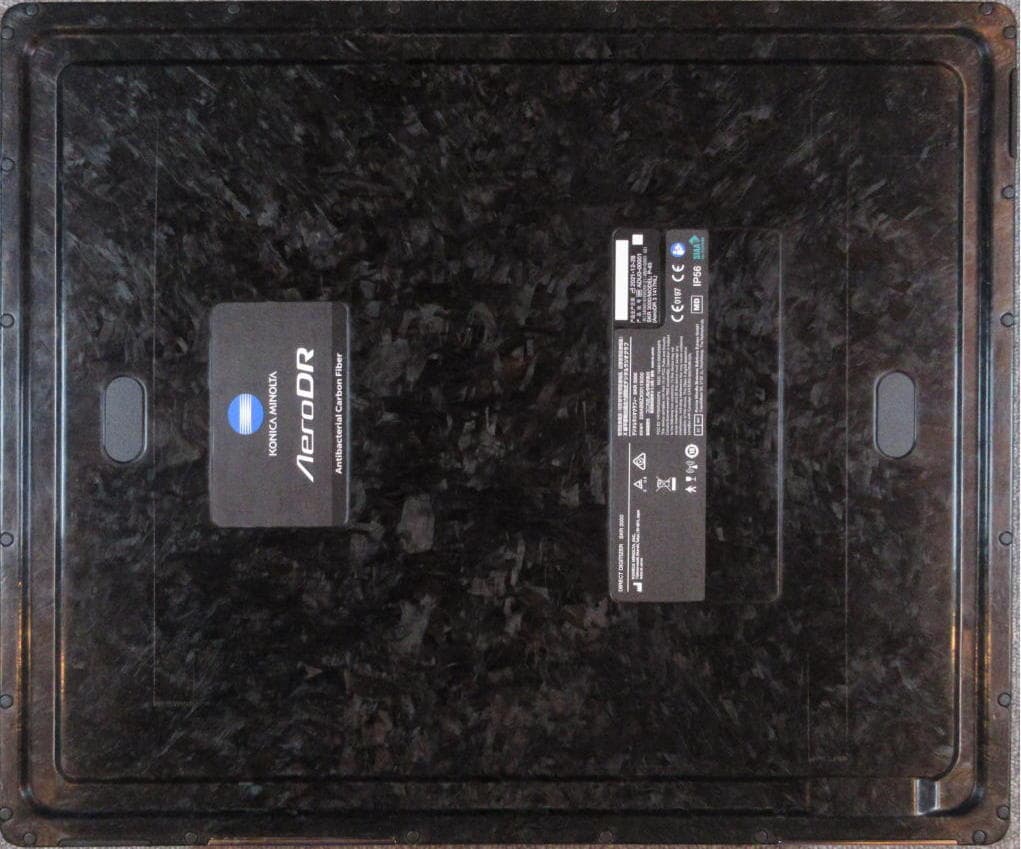
YR7SKR3000P8
Feb 23, 2022SKR 3000
Equipment Class
DTS - Digital Transmission System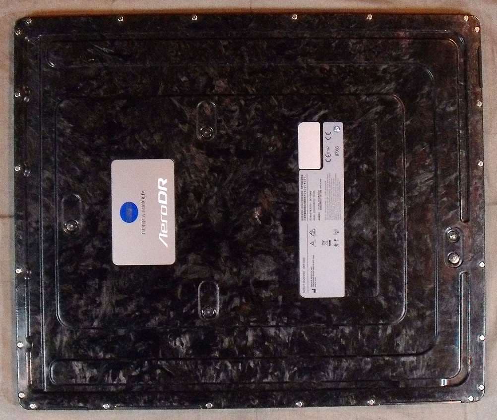
YR7SKR3000P7
May 30, 2021SKR 3000
Equipment Class
NII - Unlicensed National Information Infrastructure TX
YR7AERODRP2
Dec 27, 2011AeroDR SYSTEM
Equipment Class
DTS - Digital Transmission System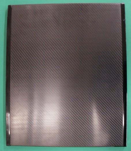
YR7AERODRP1
Oct 26, 2010AeroDR SYSTEM
Equipment Class
DTS - Digital Transmission System