YVAUG1000RA902-928 MHz ISM BAND REPEATER
Green Badge LLC d/b/a UgMO Technologies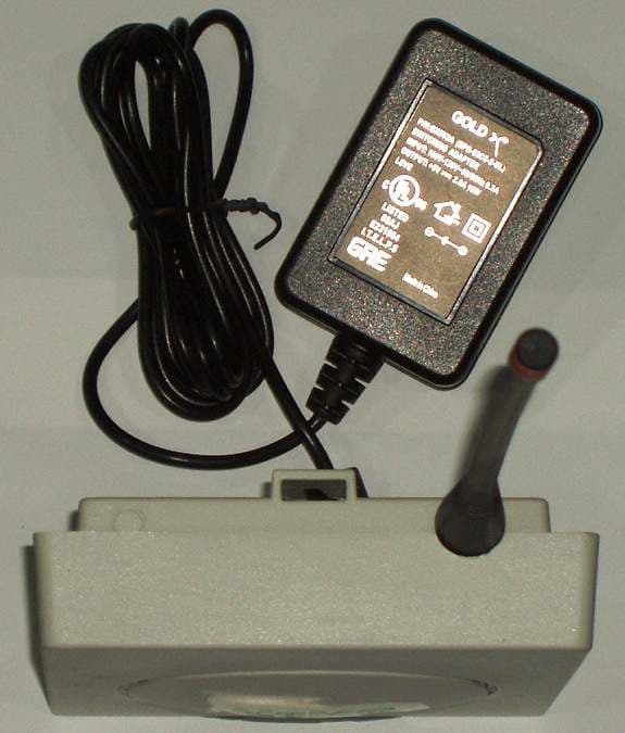
Click to zoom
Application Details
- Equipment Class
- DSS - Part 15 Spread Spectrum Transmitter
- Date of Grant
- Jul 18, 2013
- Application Purpose
- Original Equipment
- Date of Application
- Jul 18, 2013
- Equipment Note
- 902-928 MHz ISM BAND REPEATER
- Frequency Range
- 903.05300000 - 927.49200000
- Country
- United States
Documents & Files
Document Text
Text extracted from the exhibit documents filed with the FCC. Open a document above to read the original.
Users Manual
Quick Installation & Start Guide The UgMO UG1000R-A Repeater is part of the UG1000 f amily of products. The Repeater extends range and helps form a multihop above ground mesh network between controllers, bridges and other repeaters of the UG1000 product family. • Remote configuration and alert reporting • Software upgradeable to allow for future feature expansion UG1000 Wireless Repeater The UG1000R-A Wireless Repeater serves as a range e xtender. This device is able to join an above grou nd multihop mesh network which then allows signals from undergr ound sensors to travel above ground and reach contr ollers (UG1000C-A), other repeaters and Bridges (UG1000B o r UG1000B-A). The UG1000R-A is typically installed outdoors and i s wall mounted. The Repeater is powered using a wa ll wart that is supplied with the unit. The external power supply is connected to the repeater per the following diag ram. Figure 1 Wirirng Diagram for the Repeater A repeater after powering up joins an existing abov e ground Unet. This implies a controller or bridge must already be present in the network for the repeater to be able to join the network. + - Once powered, a red LED on the front of the Repeate r will aluminate followed by a series of Green LEDs as the bridge searches the area for any existing hardware or netw orks. The LEDs are very helpful in determining the current state and operation of the bridge. Regulatory Notices FCC ID: YVAUG1000RA; IC ID: 10216A-UG1000RA M/N: UG1000R-A This device complied with Part 15 of the FCC Rules and Industry Canada License Exempt RSS Standard(s). Operation is subject to the following two conditions: (1) This device may not cause harmful interference, and (2) This device must accept any interference receiv ed, including interference that may cause undesired operation. This equipment has been tested and found to comply with the limits for Class B Digital Device, pursuant to Part 15 of the FCC Rules. These limits are designed to provide reasonable pro tection against harmful interference in a residenti al installation. • This device may only be used with the approved inte rnal antenna that is shipped with the unit and inst alled per installation instructions. The use of any other antennas will i nvalidate the unit’s FCC Part 15 certification. • To reduce potential radio interference to other use rs, the antenna type and its gain should be so chose n that the equivalent isotropically radiated power (e.i.r.p.) is not more than that permitted for successful communication. Operating the device with the supplied antenna will ensure that this req uirement is met. This equipment generates and can radiate radio freq uency energy and, if not installed and used in accor dance with the instructions, may cause harmful interference to radio communicati ons. However, there is no guarantee that interferenc e will not occur in a particular installation. If this equipment does cause harmful interference t o radio or television reception, which can be determ ined by turning the equipment off and on, the user is encouraged to try to correct the interference by one or more of the following measures. • Reorient or relocate the receiving antenna • Increase the separation between the equipment and r eceiver • Connect the equipment into an outlet on a circuit d ifferent from that to which the receiver is connect ed • Consult the dealer or an experienced radio/TV techn ician for help Any changes or modifications not expressly approved by the party responsible for compliance could void the user’s authority to operate the equipment. A separation distance of 20 cm should be observed to maintain compliance with the FCC’s RF exposure guidelines set out in OET Bulletin 65. This Class B digital apparatus complies with Canadi an ICES-003. Cet appareil numérique de la classe B est conforme à la norme NMB-003 du Canada.
Cover Letter(s)
UgMO Technologies 840 First Avenue, Suite 300 King of Prussia, PA 19406 Phone 484 690 0570 Fax 510 688 2429 Email: [email protected] www.ugmo.com May 17, 2013 Timco Engineering, Inc. 849 N.W. State Road 45 P.O. Box 370 Newberry, Florida 32669 Re: Confidentiality Request Regarding Application for Certification of FCC ID: YVAUG1000RA Dear Sir: Pursuant to Sections 0.457 and 0.459 of the Commission’s Rules, we hereby request confidential treatment of information accompanying this application as outlined below: Exhibit Type File Name Schematic Diagram Block Diagram Operating Description Schematic_Diagram.pdf Block_Diagram.pdf Description.pdf The above materials contain trade secrets and proprietary information not customarily released to the public. The public disclosure of these materials may be harmful to the applicant and provide unjustified benefits to its competitors. The applicant understands that pursuant to Section 0.457 of the Rules, disclosure of this application and all accompanying documentation will not be made before the date of the Grant for this application. Sincerely, Kathy Sohrabi, Ph.D. Vice President of Engineering UgMO Technologies
Cover Letter(s)
UgMO Technologies 840 First Avenue, Suite 300 King of Prussia, PA 19406 Phone 484 690 0570 Fax 510 688 2429 Email: [email protected] www.ugmo.com May 17, 2013 Timco Engineering, Inc. 849 N.W. State Road 45 P.O. Box 370 Newberry, Florida 32669 Re: Letter of Agency for FCC & Industry Canada Compliance Testing Please be advised that I appoint Peter J. Walsh, NCE of Walshire Labs, LLC to act as our agent in the preparation of this application for equipment certification of the Model UG1000R-A, (FCC ID: YVAUG1000RA and IC: 10216A-UG1000RA). I certify that submitted documents properly describe the device or system for which equipment certification is sought. I also certify that each unit manufactured, imported or marketed, as defined in Federal Communication Commission’s regulations will have affixed to it a label identical to that submitted for approval with this application. For instances where our authorized agent signs the application for certification on our behalf, I acknowledge that all responsibility for complying with the conditions of certification still resides with Green Badge LLC D/B/A UgMO Technologies, 840 First Avenue, Suite 300, King of Prussia, PA 19406. Dated this: 17 th day May 2013 By: Kathy Sohrabi (Signature) (Printed Name) Title: Vice President of Engineering Email: [email protected] On behalf of: Green Badge LLC, D/B/A UgMO Technologies Telephone: 484 690 0570
External Photos
UgMO Technologies External Photographs Exhibit FCC ID: YVAUG1000RA IC: 10216A-UG1000RA Page 1 of 4 Photo 1 – Front View UgMO Technologies External Photographs Exhibit FCC ID: YVAUG1000RA IC: 10216A-UG1000RA Page 2 of 4 Photo 2 – Back View UgMO Technologies External Photographs Exhibit FCC ID: YVAUG1000RA IC: 10216A-UG1000RA Page 3 of 4 Photo 3 – Top Side View UgMO Technologies External Photographs Exhibit FCC ID: YVAUG1000RA IC: 10216A-UG1000RA Page 4 of 4 Photo 4 – Bottom/Sides View
ID Label/Location Info
UgMO Technologies ID Label Photograph Exhibit FCC ID: YVAUG1000RA IC: 10216A-UG1000RA Page 1 of 1 Photo 1 – Sample Label and Location Photo 2 – Close Up of the Label
Internal Photos
UgMO Technologies Internal Photographs Exhibit FCC ID: YVAUG1000RA IC: 10216A-UG1000RA Page 1 of 5 Photo 1 – Top View of the Radio Board UgMO Technologies Internal Photographs Exhibit FCC ID: YVAUG1000RA IC: 10216A-UG1000RA Page 2 of 5 Photo 2 – Bottom View of the Radio Board UgMO Technologies Internal Photographs Exhibit FCC ID: YVAUG1000RA IC: 10216A-UG1000RA Page 3 of 5 Photo 3 – Top View of the Main Board UgMO Technologies Internal Photographs Exhibit FCC ID: YVAUG1000RA IC: 10216A-UG1000RA Page 4 of 5 Photo 4 – Bottom Top View of the Main Board UgMO Technologies Internal Photographs Exhibit FCC ID: YVAUG1000RA IC: 10216A-UG1000RA Page 5 of 5 Photo 5 – Top View with the Cover Removed
Operational Description
UgMO Technologies Antenna Description Exhibit FCC ID: YVAUG1000RA IC: 10216A-UG1000RA Page 1 of 1 The radio board includes an integrated Printed Circuit Board (PCB) trace antenna with a nominal gain of -2.0 dBi. The PCB antenna employs a topology that is compact and supports an omni- directional radiation pattern. Due to the mounting position of the device, the antenna polarization is vertical.
RF Exposure Info
UgMO Technologies MPE Calculation Exhibit FCC ID: YVA1000RA IC: 10216A-UG1000RA Page 1 of 2 Prediction of MPE Limit for a Specified Distance Reference: OET Bulletin 65, Edition 97-01 The power density formula is as follows: Table 1 – MPE Calculation for OET Bulletin 65 Compliance Maximum peak output power at antenna terminal: 20.55 (dBm) Maximum peak output power at antenna terminal: 113.50 (mW) Antenna Gain (typical): -2.00 (dBi) Maximum Antenna Gain: 0.63 (numeric) Prediction Distance: 20.00 (cm) Prediction Frequency: 903.05 (MHz) MPE Limit for Uncontrolled Exposure at Prediction Frequency: 0.60 (mW/cm 2 ) Power Density at the Prediction Frequency: 0.0142 (mW/cm 2 ) Maximum Allowable Antenna Gain: 14.26 (dBi) Margin of Compliance at 20 cm: 16.26 (dB) UgMO Technologies MPE Calculation Exhibit FCC ID: YVA1000RA IC: 10216A-UG1000RA Page 2 of 2 Table 2 – RSS-102 Duty Cycle Correction Calculation Total Frequency Hopping Period: 20 seconds Channel Occupancy Period: 0.3604 seconds Number of Channels: 50 seconds Cumulative On Time for Transmission: 18.02 seconds Duty Cycle: 0.901 Duty Cycle Correction Factor: -0.9 dB Table 3 – MPE Calculation for RSS-102 Compliance Maximum peak output power at antenna terminal: 20.55 (dBm) Maximum peak output power at antenna terminal: 113.50 (mW) Antenna Gain (typical): -2.90 (dBi) Maximum Antenna Gain: 0.51 (numeric) Prediction Distance: 20.00 (cm) Prediction Frequency: 903.05 (MHz) MPE Limit for Uncontrolled Exposure at Prediction Frequency: 0.60 (mW/cm 2 ) Power Density at the Prediction Frequency: 0.0116 (mW/cm 2 ) Maximum Allowable Antenna Gain: 14.26 (dBi) Margin of Compliance at 20 cm: 17.16 (dB)
Test Report
Walshire Labs, LLC 8545 126 th Avenue North Largo, FL 33773 USA Telephone: (727) 530'8637 47 C.F.R. Part 15 FCC Rules, Subpart C & Industry Canada RSS'GEN Issue 3 & RSS'210 Issue 8 Test Results for the Augusta Irrigation Controller Repeater Unit Equipment: Augusta Repeater Unit Client: Green Badge LLC D/B/A UgMO Technologies Address: 840 First Ave., Suite 300 King of Prussia, PA 19406 Test Report Number: FCCIR'UGMO'06'04'13 Date: July 12, 2013 Total Number of Pages: 62 NVLAP LAP Code: 20012570 FCC Test Site Registration Number: 830450 Industry Canada Site Number 7868A71 Test Report ID: FCCIR7UGMO706704713 Title: UgMO Augusta Repeater Unit – FCC ID: YVAUG1000RA IC: 10216A-UG1000RA FCC Part 15 / RSS7210 Test Report Page: 2 of 62 Table of Contents 1 IDENTIFICATION SUMMARY..........................................................................................................................4 1.1 TEST REPORT...............................................................................................................................................4 1.2 TESTING LABORATORY..................................................................................................................................4 1.3 LIMITS AND RESERVATIONS...........................................................................................................................4 1.4 CLIENT INFORMATION....................................................................................................................................5 1.5 DATES..........................................................................................................................................................5 1.6 DEVICE UNDER TEST (DUT)..........................................................................................................................5 2 GENERAL INFORMATION..............................................................................................................................6 2.1 PRODUCT DESCRIPTION................................................................................................................................6 2.2 INTERFACE CABLE DETAILS...........................................................................................................................6 2.3 PERIPHERAL DEVICES...................................................................................................................................6 2.4 TEST METHODOLOGY....................................................................................................................................6 2.5 TEST FACILITY..............................................................................................................................................6 2.6 DEVIATIONS..................................................................................................................................................6 3 SYSTEM TEST CONFIGURATION..................................................................................................................7 3.1 JUSTIFICATION..............................................................................................................................................7 3.2 SPECIAL ACCESSORIES.................................................................................................................................7 3.3 EQUIPMENT MODIFICATIONS..........................................................................................................................8 4 CONDUCTED EMISSIONS DATA...................................................................................................................9 4.1 TEST PROCEDURE......................................................................................................................................10 4.2 MEASURED DATA........................................................................................................................................11 4.3 CONDUCTED EMISSIONS TEST INSTRUMENTATION........................................................................................14 4.4 CONDUCTED EMISSIONS PHOTOGRAPHS......................................................................................................14 5 RADIATED EMISSIONS DATA......................................................................................................................16 5.1 TEST PROCEDURE......................................................................................................................................19 5.2 TEST DATA.................................................................................................................................................20 5.3 TEST INSTRUMENTATION USED, RADIATED MEASUREMENT...........................................................................24 5.4 FIELD STRENGTH CALCULATION..................................................................................................................24 5.5 RADIATED EMISSIONS PHOTOGRAPHS..........................................................................................................25 6 ANTENNA REQUIREMENT...........................................................................................................................29 6.1 TEST PROCEDURE......................................................................................................................................29 6.2 TEST DATA.................................................................................................................................................29 6.3 ANTENNA PHOTOGRAPHS............................................................................................................................30 7 BANDWIDTH DATA.......................................................................................................................................31 7.1 TEST PROCEDURE.....................................................................…
Text truncated - open the document above for the full version.
Test Setup Photos
UgMO Technologies Test Set-up Photographs Exhibit FCC ID: YVAUG1000RA IC: 10216A-UG1000RA Page 1 of 6 Photo 1 – Front View of the Radiated Emissions Test Set-up UgMO Technologies Test Set-up Photographs Exhibit FCC ID: YVAUG1000RA IC: 10216A-UG1000RA Page 2 of 6 Photo 2 – Rear View of the Radiated Emissions Test Set-up 30 - 1000 MHz UgMO Technologies Test Set-up Photographs Exhibit FCC ID: YVAUG1000RA IC: 10216A-UG1000RA Page 3 of 6 Photo 3 – Rear View of the Radiated Emissions Test Set-up 1 – 10 GHz UgMO Technologies Test Set-up Photographs Exhibit FCC ID: YVAUG1000RA IC: 10216A-UG1000RA Page 4 of 6 Photo 4 – Rear View of the Radiated Emissions Test Set-up with the Loop Antenna UgMO Technologies Test Set-up Photographs Exhibit FCC ID: YVAUG1000RA IC: 10216A-UG1000RA Page 5 of 6 Photo 5 – Antenna Port Conducted Test Set-up UgMO Technologies Test Set-up Photographs Exhibit FCC ID: YVAUG1000RA IC: 10216A-UG1000RA Page 6 of 6 Photo 6 – AC Mains Conducted Emissions Test Set-up
Contact Information
Applicant
Kathy Sohrabi(Vice President of Engineering)
Test Firm
Walshire Labs, LLCPeter Walsh
Technical Specifications
| # | Rule Parts | Frequency Range | Power Output |
|---|---|---|---|
| 1 | 15C | 903.053 MHz - 927.492 MHz | 114.00 mW |
Other Applications from Green Badge LLC d/b/a UgMO Technologies
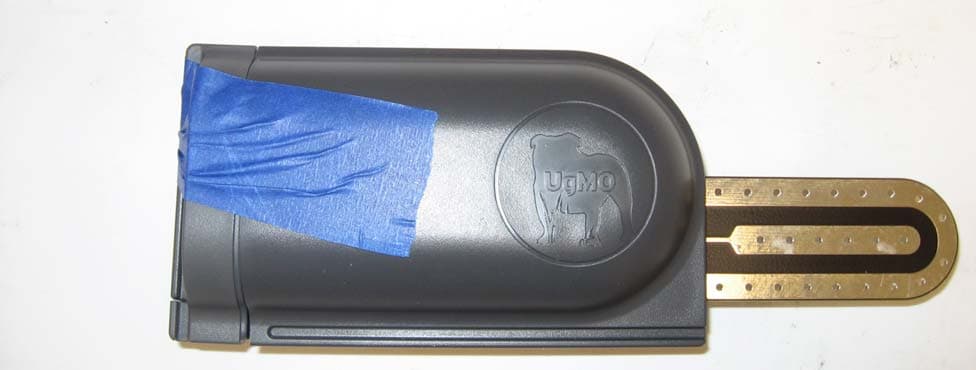
YVAUG400S
Dec 19, 2013Wireless Ground Sensor
Equipment Class
DSC - Part 15 Security/Remote Control Transmitter
YVAUG1000BA
Jul 18, 2013902-928 MHz ISM BAND BRIDGE
Equipment Class
DSS - Part 15 Spread Spectrum Transmitter
YVAUG1000R
Sep 16, 2012902 - 928 MHz ISM BAND REPEATER
Equipment Class
DSS - Part 15 Spread Spectrum Transmitter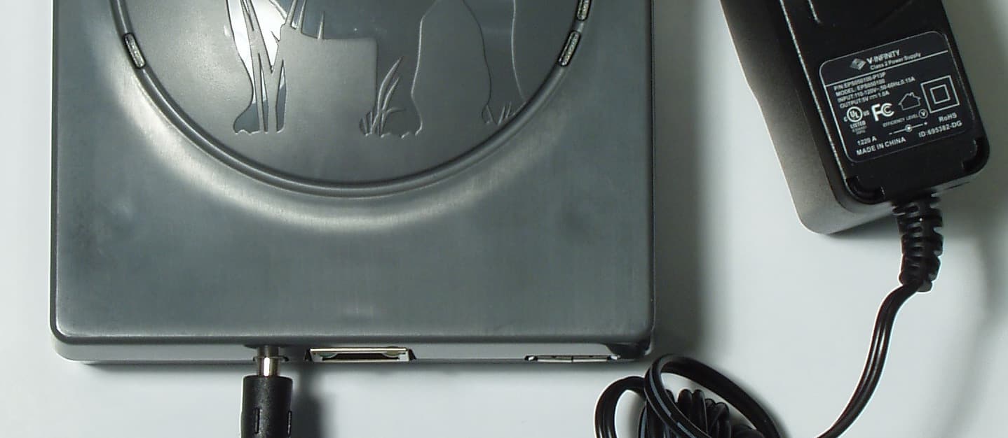
YVAUG1000B
Sep 10, 2012902 - 928 MHZ ISM BAND BRIDGE
Equipment Class
DSS - Part 15 Spread Spectrum Transmitter
YVAUG1000C
Sep 04, 2012902-928 MHz FREQUENCY HOPPING IRRIGATION CONTROLLER
Equipment Class
DSS - Part 15 Spread Spectrum Transmitter