YVAUG400SWireless Ground Sensor
Green Badge LLC d/b/a UgMO Technologies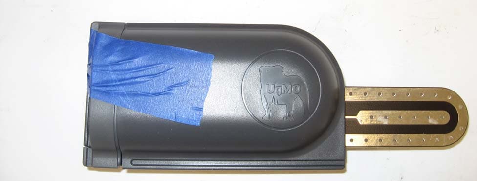
Click to zoom
Application Details
- Equipment Class
- DSC - Part 15 Security/Remote Control Transmitter
- Date of Grant
- Dec 19, 2013
- Application Purpose
- Original Equipment
- Date of Application
- Dec 19, 2013
- Equipment Note
- Wireless Ground Sensor
- Frequency Range
- 434.00000000 - 434.00000000
- Country
- United States
Documents & Files
Document Text
Text extracted from the exhibit documents filed with the FCC. Open a document above to read the original.
Users Manual
UgMO UG400S User Manual Introduction UgMO™ monitors soil moisture in the root zones of your plants. UgMO saves water and improves plant health by limiting overwatering for lawns and ornamental plantings. The UG400S paired with UG1000 controllers or PH100‐B devices will enable water savings using smart irrigation algorithms. UgMO wireless sensors have a patented electronic moisture and optional salinity sensing circuit and low power radio signal. Two uniquely configured batteries (supplied and installed) provide an operating life of up to 5 years. UgMO devices are weather resistant for outdoor use. Wireless Sensors are buried at depths from 1” to 4” according to plant and soil types and operate at distances up to 600 feet, depending on soil type, depth, and line of site to the Base Station. UgMO sensors are easy to install, effective and long lasting. It is not uncommon for a typical home to reduce water use by as much as 45%. UgMO UG400S sensor is a new generation of wireless sensors that is designed to be compatible with the existing ProHome and UG1000 product line. The UG400S is a direct replacement for PH100‐WS sensors. The device is intended for installation underground. It has a on/off switch that is activated by means of turning the battery door one quarter turn. The device will not sense anything for the first minute after power up, allowing the device to be inserted in position underground. Compatibility UG400S is compatible with PH100-R, PH100-B and UG1000 devices. Installing the Sensor Place the sensors on top of the ground in the corresponding zones that they represent for the associated above ground UgMO device (Refer to manuals for UgMO PhoMO and UG1000 devices for more detail). The ideal location in each zone is between sprinkler heads, in the driest part of the zone and with the clearest line of sight to the above ground device when at all possible. The sensors should be placed perpendicular to the above ground device, so that the broad side of the sensor body is facing in the direction of the device. Once all sensors are placed on top of the ground in the correct zones, go back to the above ground device and restart it (if a PH100‐B device) or start the sensor pairing activity. 3. Go back to the zone one sensor. Dig a hole using a small shovel or a hole‐cutter approximately one and quarter times the length of the sensor and three times the width (keeping in mind the orientation. Burry the sensor and ensure it is heard at the intended Base Station or Controller. Placement of The Sensor 1. Using a 1.5” putty knife or something similar, create a horizontal slit in the soil, so the center of the slit is 1.5” to 1.75” below the top of the soil and within the root zone of the plant. 2. Take some dirt from the hole and perform a field test to identify the soil’s physical properties which will be used later for setting the zone Wetness Settings (field test instruction can be found in the manual in Appendix B). 3. Turn the sensor on using the turn switch at the back side of the sensor. Ensure steps 4 – 6 are completed within 1 minute of powering on of the sensor. Make sure the whisker is attached to the sensor body prior to powering on of the sensor. 4. Insert the sensor blade into the slit you created without wiggling or applying any side‐to‐side pressure on the sensor blade. 5. Place the whisker, loop side down so that the top is out of the ground at a level that is close to the length of the grass or where it can be covered by a thin layer of mulch, (If sensor is located in a planting bed). 6. Bury the sensor and whisker, making sure to pack the soil firmly as you fill the hole and place the turf cap back on. Operations Once the sensor is installed it will require no intervention from user, with the exception of change of battery. The device reports its battery level. Notices This device complies with Part 15 of the FCC Rules. Operation is subject to the following two conditions: (1) This device may not cause harmful interference, and (2) This device must accept any interference received, including interference that may cause undesired operation. This equipment has been tested and found to comply with the limits for Class B Digital Device, pursuant to Part 15 of the FCC Rules. These limits are designed to provide reasonable protection against harmful interference in a residential installation. This equipment generates and can radiate radio frequency energy and, if not installed and used in accordance with the instructions, may cause harmful interference to radio communications. However, there is no guarantee that interference will not occur in a particular installation. If this equipment does cause harmful interference to radio or television reception, which can be determined by turning the equipment off and on, the user is encouraged to try to correct the interference by one or more of the following measures. Reorient or relocate the receiving antenna Increase the separation between the equipment and receiver Connect the equipment into an outlet on a circuit different from that to which the receiver is connected Consult the dealer or an experienced radio/TV technician for help Any changes or modifications not expressly approved by the party responsible for compliance could void the user’s authority to operate the equipment Les changements ou modifications non approuvés expressément par la partie responsable de la conformité pourrait annuler l'autorité de l'utilisateur à faire fonctionner l'équipement. This device complies with Industry Canada licence‐exempt RSS standard(s). Operation is subject to the following two conditions: (1) this device may not cause interference, and (2) this device must accept any interference, including interference that may cause undesired operation of the device. Le présent appareil est conforme aux CNR d'Industrie Canada applicables aux appareils radio exempts de licence. L'exploitation est autorisée aux deux conditions suivantes : (1) l'ap…
Text truncated - open the document above for the full version.
ID Label/Location Info
NWA: 11 00 00 3C SN: 2 ‐ 009 ‐ 0008DE ‐ 03 ‐ G1 ‐ 00 ‐ 8a Made in USA by UgMO ©2012 This device complies with Part 15 of the FCC Rules.Operation is subject to the following two conditions:(1) This device may not cause harmful interference(2) This device must accept any interference receivedincluding interference that may cause undesired operation. M/N: UG400S FCC ID: YVAUG400S 2.2 inch 0.375 inch 2.2 inch Label 1 • All labels should use THT B422 material from Brady or similar. • UL recognized or listed. RoHS compliant. • Appropriate for use outdoors. • WEE compliant. Label 2 • Same as label 1. 0.375 inch Label position: The labels are places at the bottom of the sensor enclosure. See the assembly Drawing excerpt on next page. Label Location At the bottom of the enclosure
Test Report
Nemko USA, Inc. 2210 Faraday Ave, Suite 150 Carlsbad, CA 92008 Phone (760) 444-3500 Fax (760) 444-3005 FCC Part 15 Subpart C, 15.231: 20/11/2013 Certification Test Report In Accordance With: FCC Part 15 Subpart C, 15.231& 15.231(e) Applicant: Advanced Sensor Technology 840 First Ave, Suite 300 King of Prussia, PA 19406 Equipment Under Test (EUT): Moisture sensor Model: Cypress systems FCC ID: YVAUG400S IC: 10216A-UG400S Tested By: Nemko USA Inc. 2210 Faraday Avenue, Suite 150 Carlsbad, CA 92008 Test Report Number: 2013 08226596 FCC Date: September 3, 2013 Project Number 43834 NEX Number 149167 Total Number of Pages: 29 Nemko USA, Inc. 2210 Faraday Avenue, Suite 150, Carlsbad, CA 92008 Phone (760) 444-3500 Fax (760) 444-3005 Report Number: 2013 08226596 FCC FCC ID: YVAUG400S Specification: FCC Part 15 Subpart C, 15.231(e) Page 2 of 29 Applicant Affirmation Kathy Sohrabi, PhD representing Advanced Sensor Technology hereby affirms: a) That he/she has reviewed and concurs that the test shown in this report are reflective of the operational characteristics of the device for which certification is sought; b) That the device in this test report will be representative of production units; c) That all changes (in hardware and software/firmware) to the subject device will be reviewed. d) That any changes impacting the attributes, functionality or operational characteristics documented in this report will be communicated to the body responsible for approving (certifying) the subject equipment. Kathy Sohrabi, PhD Printed name of official Signature of official 840 First Ave, Suite 300 August 26, 2013 King of Prussia, PA 19406 Date +1 484.524.3468 [email protected] Telephone number Email address of official NOTE—This affirmation must be signed by the responsible party before it is submitted to a regulatory body for approval. Nemko USA, Inc. 2210 Faraday Avenue, Suite 150, Carlsbad, CA 92008 Phone (760) 444-3500 Fax (760) 444-3005 Report Number: 2013 08226596 FCC FCC ID: YVAUG400S Specification: FCC Part 15 Subpart C, 15.231(e) Page 3 of 29 Section 1. Summary of Test Results 1.1 General All measurements are traceable to national standards These tests were conducted on a sample of the equipment for the purpose of demonstrating compliance with Part 15; Subpart C. Radiated tests were conducted is accordance with ANSI C63.4-2003. Radiated emissions are made on an open area test site. A description of the test facility is on file with the FCC and Industry Canada. The assessment summary is as follows: Apparatus Assessed: Moisture sensor Model: Cypress systems Specification: FCC Part 15 Subpart C, 15.231 Date Received in Laboratory: August 26, 2013 Compliance Status: Complies Exclusions: None Non-compliances: None Nemko USA, Inc. 2210 Faraday Avenue, Suite 150, Carlsbad, CA 92008 Phone (760) 444-3500 Fax (760) 444-3005 Report Number: 2013 08226596 FCC FCC ID: YVAUG400S Specification: FCC Part 15 Subpart C, 15.231(e) Page 4 of 29 1.2 Report Release History REVISION DATE COMMENTS - January 13, 2010 Prepared By: Kevin Marquess - January 13, 2010 Initial Release: Alan Laudani Note that the results contained in this report relate only to the items tested and were obtained in the period between the date of initial receipt of samples and the date of issue of the report. This test report has been completed in accordance with the requirements of ISO/IEC 17025. Nemko USA Inc. authorizes the applicant to reproduce this report provided it is reproduced in its entirety and for use by the company’s employees only. Any use which a third party makes of this report, or any reliance on or decisions to be made based on it, are the responsibility of such third parties. Nemko USA Inc. accepts no responsibility for damages, if any, suffered by any third party as a result of decisions made or actions based on this report. Kevin Marquess, Senior RF/EMC Engineer Alan Laudani, Senior RF/EMC Engineer Nemko USA, Inc. 2210 Faraday Avenue, Suite 150, Carlsbad, CA 92008 Phone (760) 444-3500 Fax (760) 444-3005 Report Number: 2013 08226596 FCC FCC ID: YVAUG400S Specification: FCC Part 15 Subpart C, 15.231(e) Page 5 of 29 TABLE OF CONTENTS Section 1. Summary of Test Results .......................................................................... 2 1.1 General ............................................................................................................. 3 1.2 Report Release History ..................................................................................... 4 Section 2: Equipment Under Test .................................................................................... 6 2.1 EUT description ................................................................................................. 6 2.2 Technical Specifications of the EUT .................................................................. 6 Section 3: Test Conditions ............................................................................................... 7 3.1 Specifications .................................................................................................... 7 3.2 Deviations From Laboratory Test Procedures ................................................... 7 3.3 Test Environment .............................................................................................. 7 3.3 Test Equipment ................................................................................................. 7 Section 4: Observations .................................................................................................. 8 4.1 Modifications Performed During Assessment .................................................... 8 4.2 Record Of Technical Judgements ..................................................................... 8 4.3 EUT Parameters Affecting Compliance ............................................................. 8 4.4 Tests Deleted ...................................................................................................…
Text truncated - open the document above for the full version.
Contact Information
Applicant
Kathy Sohrabi(Vice President of Engineering)
Test Firm
Nemko USA, Inc. - San Diego EMC DivisionJan Blomgren
[email protected]760-444-3500
Technical Specifications
| # | Rule Parts | Frequency Range | Power Output |
|---|---|---|---|
| 1 | 15.231,15.231(e) | 434 MHz - 434 MHz | - |
Other Applications from Green Badge LLC d/b/a UgMO Technologies
YVAUG1000BA
Jul 18, 2013902-928 MHz ISM BAND BRIDGE
Equipment Class
DSS - Part 15 Spread Spectrum Transmitter
YVAUG1000RA
Jul 18, 2013902-928 MHz ISM BAND REPEATER
Equipment Class
DSS - Part 15 Spread Spectrum Transmitter
YVAUG1000R
Sep 16, 2012902 - 928 MHz ISM BAND REPEATER
Equipment Class
DSS - Part 15 Spread Spectrum Transmitter
YVAUG1000B
Sep 10, 2012902 - 928 MHZ ISM BAND BRIDGE
Equipment Class
DSS - Part 15 Spread Spectrum Transmitter
YVAUG1000C
Sep 04, 2012902-928 MHz FREQUENCY HOPPING IRRIGATION CONTROLLER
Equipment Class
DSS - Part 15 Spread Spectrum Transmitter