Z5J-REACH9771Mobile Phone
REACH Tech (Xiamen) Co., Ltd.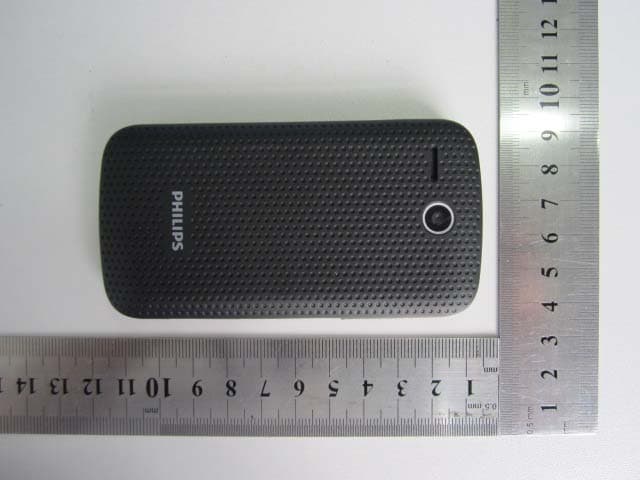
Click to zoom
Application Details
- Equipment Class
- DTS - Digital Transmission System
- Date of Grant
- Oct 28, 2012
- Application Purpose
- Original Equipment
- Date of Application
- Oct 23, 2012
- Equipment Note
- Mobile Phone
- Frequency Range
- 2412.00000000 - 2462.00000000
- Country
- China
Documents & Files
Document Text
Text extracted from the exhibit documents filed with the FCC. Open a document above to read the original.
Users Manual
Your phone Headphone Side volume key Micro-SD card Power key Charger/Micro USB port connector Touch screen Home Menu Back Searc Loudspeaker Camera Front camera Your phone 1 Home screen You may activate functions of this device by operations on the touch screen. There are five main screens, which could be switched by sliding to the left or the right. Tap [Home Key] in any interface to go back to the main screen. Tap an application icon on the main screen to start that application. Tap Apps Panel to find all applications. Your phone’s home screen consists of the following areas: Status Application icons Apps Panel Your phone 2 Keys Learn about the main keys: Key Definition Function Power key -Press to turn on/off the screen display. -Press and hold to access the Phone options, choose Silent, Airplane mode, Power off or Mobile Data. Menu key -Open options menu available on the current screen. -Hide the onscreen options menu while it's opened. Home key -Return to the home screen. -Press and hold to open the list of recent applications. Back key -Back to the previous screen or exit. -Hide the onscreen keyboard while it’s opened. Search key -Open the search input box. Volume key -Volume up/down. -Press to turn to silent mode while there is a call. Notification When you g the Notificat notification o received. Th switch betwe To open the the status ba If you have s down the sc You can als Home scre e n Panel get a new notificatio tions panel to see w or new information he Notifications pan een recently-opene e Notifications pane ar, then slide your f several notification creen to see them a o open the Notifica en by tapping> on, you can open what event you have nel lets you quickly ed apps. el, press and hold finger downward. s, you can scroll all. ations panel on the Notifications. Status Icon Icons F Y r Y r F Y G b r C C n Function Your phone will not receiving a call. Your phone will vib receiving a call. Flight mode activat Your phone is conn GSM/WCDAM netw bars are shown the reception is. Call in progress. Call on hold. Your phone 3 t ring when rate when ted. nected to a work. The more e better the Your phone 4 You have a missed call. New SMS or MMS. WLAN is activated. The bars indicate the battery level. Connect to PC. Bluetooth is activated. The alarm clock is activated. The headset is plugged into the phone. Indicate the memory card is used. Error occurred or caution required. Table of contents 5 Table of contents GETTING STARTED ................................... 6 Install SIM/UIM Card and Battery ........ 6 Insert a Memory Card .......................... 8 Charging the Battery ........................... 8 Turn Your Phone On and Off ............... 9 Password ............................................. 9 BASIC FUNCTION .................................... 10 Calls ................................................... 10 Messaging ......................................... 11 Email .................................................. 12 MULTIMEDIA ............................................ 14 Camera .............................................. 14 Music ................................................. 15 FM Player .......................................... 16 Apps .................................................. 16 SEARCH AND WEB ................................. 18 Search settings ................................. 18 Web browser ..................................... 18 INTERNET CONNECTIONS .................... 19 Bluetooth ........................................... 19 WLAN ................................................ 20 SETTINGS ................................................ 21 Sound setting .................................... 21 Screen settings ................................. 21 Security setting.................................. 22 SAFETY & PRECAUTION ....................... 23 Safety Notice ..................................... 23 Care and maintenance ...................... 24 Trouble Shooting ............................... 25 Environmental Instructions ................ 26 Getting started 6 Getting started Install SIM/UIM Card and Battery Always turn off your device before installing or replacing the SIM card and battery . Battery performance depends on many factors, including network configuration, signal strength, the temperature of the environment in which you operate your device, the features and/or settings you select and use, items attached to connecting ports, and your voice, data, and other program usage patterns. To reduce risk of fire or burns: - Do not attempt to open, disassemble, or service the battery pack. - Do not crush, puncture, short external contacts, or dispose of in fire or water. - Do not expose to temperatures above 60°C (140°F). - Replace only with the battery pack designated for this product. - Recycle or dispose of used battery as stipulated by local regulations. Remove The Rear Cover: (1) If the phone is on, press and hold on/off key for 3 seconds to turn it off. (2) Hold the device with the front panel facing down, and remove the rear cover. Remove the Battery: (3) Lift up as indicated in the mark and remove the battery Gettting started 7 (4) Insert the SIM card: (5) Place the SIM card in the phone with the gold-colored contacts facing down. Insert the Battery: (6) Make sure the battery contacts are facing correctly, and push the other side of the battery gently until it is completely fixed in the battery slot. (7) Replace the battery cover. Make sure the battery contacts are facing correctly. Getting starte Insert a M Insert the M (1) Inse gold direc Remove th (2) Sligh of sl Reco card, and o ed 8 Memory Card Micro SD Card ert into the slot with den contacts facing ction as indicated in he Micro SD Card htly pull the Micro S lot. ommend to use origina or Micro SD card of S a other leading brands. P the side of the up; push in the n the picture. SD card to take out lly equipped Micro SD an Disk or Kingston Please confirm the compa Please …
Text truncated - open the document above for the full version.
Cover Letter(s)
Date: Oct 15, 2012 To: Federal Communications Commission, Authorization & Evaluation Division, 7435 Oakland Mills Road, Columbia, MD 21046 To Whom It May Concern: The REACH Tech (Xiamen) Co.,Ltd., the undersigned, hereby authorizes Mr.Wu Xuewen from Shenzhen Morlab Communications Technology Co.,Ltd., to act on the behalf of the REACH Tech (Xiamen) Co.,Ltd. solely in matters relating to the application for an FCC equipment authorization for FCC ID #Z5J-REACH9771 including the signing of documents in connection with this Application. Necessary acts carried out by REACH Tech (Xiamen) Co.,Ltd. on our behalf of the REACH Tech (Xiamen) Co., Ltd. in connection with the Application shall have the same effect as acts of the REACH Tech (Xiamen) Co.,Ltd. The REACH Tech (Xiamen) Co.,Ltd. also hereby certify that no party to this application is subject to a denial of benefits, including FCC benefits, pursuant to Section 5301 of the Anti-Drug Abuse Act of 1988, 21 U.S.C. 853(a). Thank you for your attention to this matter. Yours Sincerely, Xiaowen Tang Quality Manager REACH Tech (Xiamen) Co.,Ltd.
Cover Letter(s)
Date: Oct 15, 2012 To: Federal Communications Commission, Authorization & Evaluation Division, 7435 Oakland Mills Road, Columbia, MD 21046 Re: REACH Tech (Xiamen) Co.,Ltd. FCC ID: Z5J-REACH9771 FCC Certification Confidentiality Request Gentlemen: This letter is to comply with 47 CFR 0.457 and 0.459 pertaining to confidentiality material. REACH Tech (Xiamen) Co.,Ltd. requests that the following documents regarding this submission for FCC ID: Z5J-REACH9771 be kept confidential: Exhibit Type File Name Block Diagram CONF APPENDIX Z5J-REACH9771_Block Diagram.pdf Schematics CONF APPENDIX Z5J-REACH9771_Schematics.pdf Operational Description CONF APPENDIX Z5J-REACH9771_Operational Description.pdf Part list CONF APPENDIX Z5J-REACH9771_BOM.pdf Tune-Up-Procedure CONF APPENDIX Z5J-REACH9771_Tune up procedure.pdf Those documents contain detailed system and equipment description and related information about the product which REACH Tech (Xiamen) Co.,Ltd. considers to be confidential proprietary, a custom design and, otherwise, not releasable to the general public. Since this design is a basis form which future technological products will evolve, REACH Tech (Xiamen) Co.,Ltd.considers this information would be of benefit to its competitors, and that the disclosure of the information in these documents would give competitors an unfair advantage in the market. Yours Sincerely, Xiaowen Tang Quality Manager REACH Tech (Xiamen) Co.,Ltd.
External Photos
External Photos
ID Label/Location Info
Date: Oct. 18, 2012 Equipment Authorization Division Office of Engineering and Technology Federal Communications Commission 7435 Oakland Mills Road Columbia, MD 21046 Ref: FCC ID: Z5J-REACH9771 Dear Sirs: REACH Tech (Xiamen) Co., Ltd. requests acceptance of the labeling proposal described below for cell phone bearing FCC identifier Z5J-REACH9771. The subject cell phone are compact handheld models as shown in figure 1, authorized under 47CFR Part 22H&24E&27L for GSM&WCDMA mobile services. Figure 1. Because the majority of the cell phone housing is composed of display, speaker, operating controls and a removable battery pack, there is extremely limited space available to attach the required label carrying the FCC identifier. Attaching the label to the battery pack is not acceptable because the battery pack is a removable item. For this reason, REACH Tech (Xiamen) Co., Ltd. placing the label carrying the FCC identifier inside the battery compartment as shown in figure 2. Figure 2. The consumer packaging for these models includes the battery pack as a separate item, NOT installed on the radio. As such, the FCC identifier will be readily visible to the user before the battery pack is installed and whenever the battery pack is removed or replaced. In this location, the label will also be protected from physical abuse and remain readable for the anticipated life of the device. The consumer packaging for these models is a "gift box" which does not allow the transceiver to be seen at time of purchase. In order to meet the requirements of 47CFR Part 2.925 (d), REACH Tech (Xiamen) Co., Ltd. will add the FCC identifier " Z5J-REACH9771 " to the outside of the consumer "gift box" packaging. Thank you for your attention to this matter. Yours Sincerely, Xiaowen Tang Quality Manager REACH Tech (Xiamen) Co.,Ltd.
ID Label/Location Info
FCC ID: Z5J-REACH9771 Label Label Location
Internal Photos
Internal Photos
Test Report
SZ12090024W02 Page 2 of 44 DIRECTORY 1. GENERAL INFORMATION .................................................................................................... 3 1.1. EUT Description ....................................................................................................................... 3 1.2. Test Standards and Results ........................................................................................................ 4 1.3. Facilities and Accreditations ..................................................................................................... 5 2. 47 CFR PART 15C REQUIREMENTS .................................................................................... 6 2.1. Peak Output Power.................................................................................................................... 6 2.2. Bandwidth ................................................................................................................................. 8 2.3. Conducted Spurious Emissions ............................................................................................... 13 2.4. Power spectral density (PSD) ................................................................................................. 21 2.5. Band Edge ............................................................................................................................... 26 2.6. Conducted Emission ............................................................................................................... 32 2.7. Radiated Emission................................................................................................................... 35 Change History Issue Date Reason for change 1.0 Sep 22, 2012 First edition SZ12090024W02 Page 3 of 44 1. General Information 1.1. EUT Description EUT Type ............................. : REACH9771 Serial No. .............................. : n.a Hardware Version ................. : 9771 V3.1 Software Version .................. : Applicant .............................. : Manufacturer ........................ : E9771-eng 2.3.5 GRJ90 eng.Root.20120825.052322.test-keys Reach Tec(Xiamen) CO.,LTD 5th Floor, 51#, Wang Hai Road, Software Park II, Xiamen, Fujian Province Reach Tec(Xiamen) CO.,LTD 5th Floor, 51#, Wang Hai Road, Software Park II, Xiamen, Fujian Province Frequency Range .................. : 802.11b/g -20MHz: 2.412GHz - 2.462GHz Channel Number................... : 11 Modulation Type .................. : DSSS, OFDM Antenna Type ........................ : PIFA Antenna Antenna Gain ........................ : 0dBi Note 1: The EUT is a REACH9771, it contains WIFI Module operating at 2.4GHz ISM band;It supports 802.11b, 802.11g, and they are all tested in this report. Note 2: The frequencies allocated is F(MHz)=2412+5*(n-1) (1<=n<=11). The lowest, middle, highest channel numbers of the EUT used and tested in this report are separately 1 (2412MHz), 6 (2437MHz) and 11 (2462MHz). Note 3: For a more detailed description, please refer to Specification or User’s Manual supplied by the applicant and/or manufacturer. SZ12090024W02 Page 4 of 44 1.2. Test Standards and Results The objective of the report is to perform testing according to 47 CFR Part 15 Subpart C (Wi-Fi, 2.4GHz ISM band radiators) for the EUT FCC ID Certification: No. Identity Document Title 1 47 CFR Part 15 (10-1-09 Edition) Radio Frequency Devices Test detailed items/section required by FCC rules and results are as below: No. Section Description Result 1 15.247(a) Number of Hopping Frequency (n.a) 2 15.247(b) Peak Output Power PASS 3 15.247(a) Bandwidth PASS 4 15.247(a) Carrier Frequency Separation (n.a) 5 15.247(a) Time of Occupancy (Dwell time) (n.a) 6 15.247(c) Conducted Spurious Emission PASS 7 15.247(c) Band Edge PASS 8 15.207 Conducted Emission PASS 9 15.209 15.247(c) Radiated Emission PASS 10 15.247(d) Power spectral density (PSD) PASS The tests of Conducted Emission and Radiated Emission were performed according to the method of measurements prescribed in ANSI C63.4 2009. These RF tests were performed according to the method of measurements prescribed in KBD558074. SZ12090024W02 Page 5 of 44 1.3. Facilities and Accreditations 1.3.1. Facilities Shenzhen Morlab Communications Technology Co., Ltd. Morlab Laboratory is a testing organization accredited by China National Accreditation Service for Conformity Assessment (CNAS) according to ISO/IEC 17025. The accreditation certificate number is L3572. All measurement facilities used to collect the measurement data are located at 3/F, Electronic Testing Building, Shahe Road, Xili, Nanshan District, Shenzhen, 518055 P. R. China. The test site is constructed in conformance with the requirements of ANSI C63.7, ANSI C63.4 and CISPR Publication 22; the FCC registration number is 741109. 1.3.2. Test Environment Conditions During the measurement, the environmental conditions were within the listed ranges: Temperature (°C): 15 - 35 Relative Humidity (%): 30 -60 Atmospheric Pressure (kPa): 86-106 SZ12090024W02 Page 6 of 44 2. 47 CFR Part 15C Requirements 2.1. Peak Output Power 2.1.1. Requirement According to FCC section 15.247(b)(3), For systems using digital modulation in the 902-928 MHz, 2400-2483.5 MHz, and 5725-5850 MHz bands: The maximum peak conducted output power of the intentional radiator shall not exceed1 Watt. 2.1.2. Test Description The measured output power was calculated by the reading of the Power Meter and calibration. A. Test Setup: The EUT (Equipment under the test) which is powered by the Battery, is coupled to the Power Meter; the RF load attached to the EUT antenna terminal is 50Ohm; the path loss as the factor is calibrated to correct the reading. B. Equipments List: Description ManufacturerModel Serial No. Cal. Date Power Meter Agilent E4418B MY45100845 2012.02 SZ12090024W02 Page 7 of 44 2.1.3. Test Result The lowest, middle and highest channels are selected to perform testing to verify the conducted RF output peak …
Text truncated - open the document above for the full version.
Test Setup Photos
Test Setup Photos 1. CE 2.RE 3. CSE
Contact Information
Applicant
Xiaolin Zhu(VP)
Technical Contact
Shenzhen Morlab Communications Technology Co.,LtdXuewen Wu
[email protected]86-755-86120298
FL.3,Electronic Testing Bld, Shahe Rd, Nanshan · China
Non-Technical Contact
Shenzhen Morlab Communications Technology Co.,LtdXuewen Wu
Test Firm
Shenzhen Morlab Communications Technology Co.,LtdShu Luan
Technical Specifications
| # | Rule Parts | Frequency Range | Power Output |
|---|---|---|---|
| 1 | 15C | 2.41 GHz - 2.46 GHz | 8.00 mW |
Other Applications from REACH Tech (Xiamen) Co., Ltd.
May 13, 2014
Equipment Class
DTS - Digital Transmission System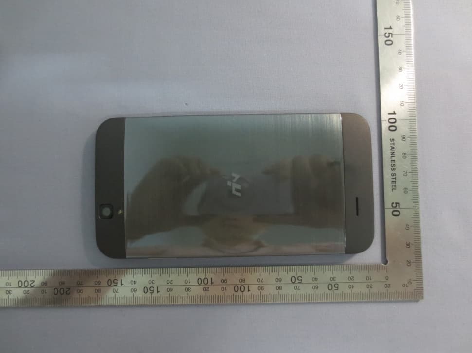
Z5JREACH-Q887R
Apr 21, 2014Smart phone
Equipment Class
DSS - Part 15 Spread Spectrum Transmitter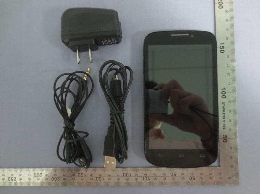
Z5JREACH-Q882
Dec 12, 2013Smart phone
Equipment Class
DSS - Part 15 Spread Spectrum Transmitter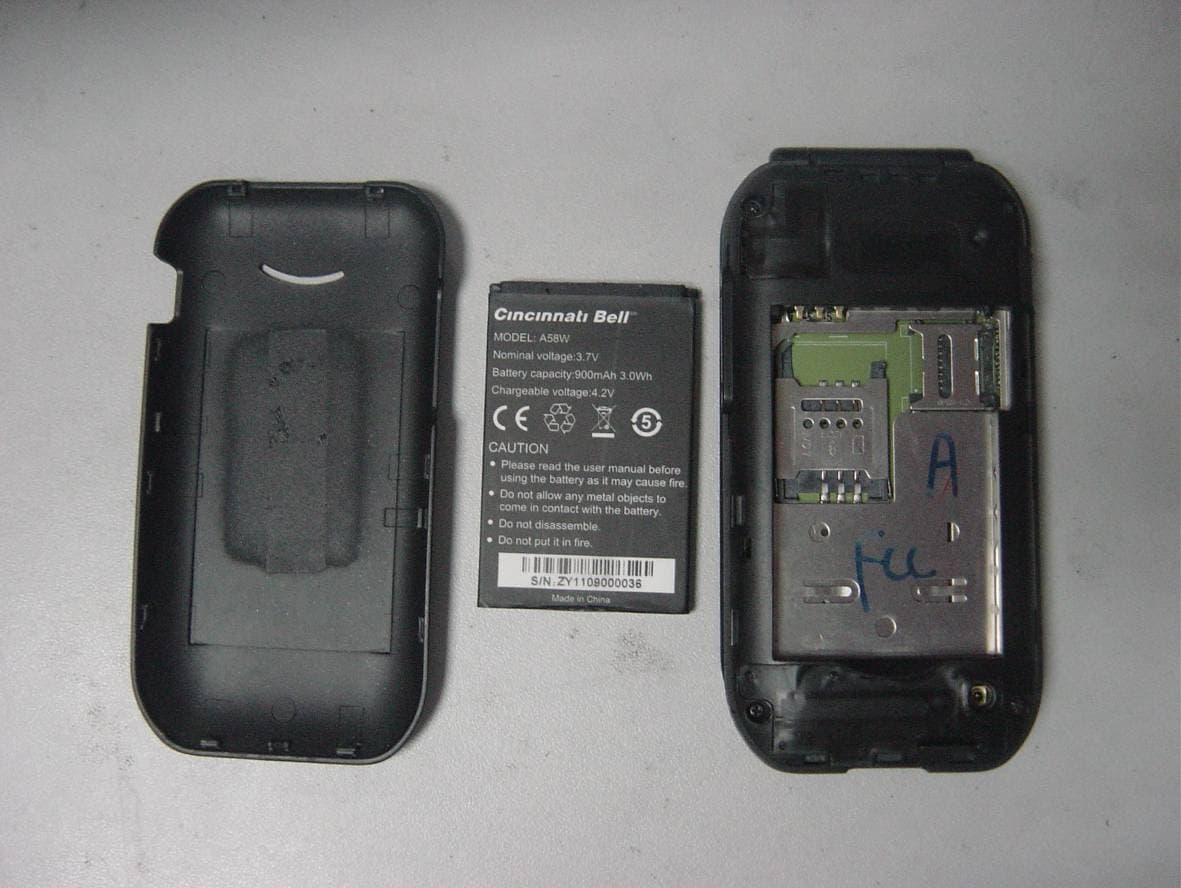
Z5J-A58W
Oct 27, 2011Mobile Phone
Equipment Class
DSS - Part 15 Spread Spectrum Transmitter