Z64-CC310XKITEvaluation board
Texas Instruments Incorporated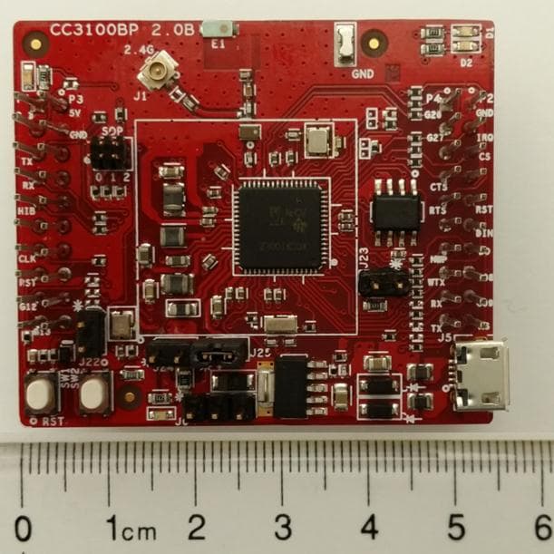
Click to zoom
Application Details
- Equipment Class
- DTS - Digital Transmission System
- Date of Grant
- Mar 24, 2014
- Application Purpose
- Original Equipment
- Date of Application
- Mar 24, 2014
- Equipment Note
- Evaluation board
- Frequency Range
- 2412.00000000 - 2462.00000000
- Country
- United States
Documents & Files
Document Text
Text extracted from the exhibit documents filed with the FCC. Open a document above to read the original.
Users Manual
User Guide 2014 SimpleLink is a trademark of Texas Instruments Incorporated. TI Proprietary Information - Strictly Private 1 CC3100BOOST (CC3100 Booster Pack) User Guide, Ver 1.1 ECS Applications ABSTRACT This document describes the CC3100BOOST (CC3100 Booster Pack). It details the features of the hardware and also explains the correct usage of the board. ABSTRACT This document describes the CC3100BOOST (CC3100 Booster Pack). It details the features of the hardware and also explains the correct usage of the board. CC3100BOOST User Guide TI Proprietary Information - Strictly Private TABLE OF CONTENTS 1 Introduction ................................................................................................................................ 4 2 Overview ...................................................................................................................................... 4 3 Hardware description ................................................................................................................ 4 3.1 Board overview ....................................................................................................................... 4 3.2 Board features ........................................................................................................................ 5 3.3 Jumper and connector information ......................................................................................... 6 3.3.1 2x20 pin connector ...................................................................................................... 6 3.4 Jumper details ........................................................................................................................ 7 3.5 LED and switches .................................................................................................................... 8 3.6 Conducted testing ................................................................................................................... 9 3.7 Current measurement ........................................................................................................... 10 4 Connecting to a PC using FTDI Board ................................................................................... 11 4.1 Jumper settings on the BP Board .......................................................................................... 11 4.2 Jumper settings on the FTDI Board ...................................................................................... 12 4.3 FTDI Board details ................................................................................................................ 13 4.3.1 Overview ................................................................................................................... 13 4.3.2 Hardware details ....................................................................................................... 14 4.3.3 Driver requirements .................................................................................................. 15 5 Connecting to a Launchpad .................................................................................................... 16 5.1 Launchpad current limitation ................................................................................................ 16 5.2 Connecting to an experimenter’s board. ............................................................................... 18 CC3100BOOST User Guide TI Proprietary Information - Strictly Private CC3100BOOST User Guide TI Proprietary Information - Strictly Private 1 Introduction This document provides a quick start guide on using the CC3100 Booster Pack Rev 2.0B . This is not applicable to other revisions of the board. 2 Overview The CC3100 Booster Pack is a board designed to interface with the TI standard Launchpad including the Tiva-C series and the MSP430 value line launchpads. In addition to the launchpads, there is support available to mate the board with a FTDI Debug board to interface directly to a PC host using USB cable. A picture of the board is presented below with the main components marked. 3 Hardware description 3.1 Board overview CC3100BOOST User Guide TI Proprietary Information - Strictly Private FIGURE 1 : HARDWARE DETAILS 3.2 Board features 2x20 pin stackable connectors On-board chip antenna with option for U.FL based conducted testing. Power from on-board LDO using USB OR 3.3V from MCU Launchpad Push buttons (2x) LEDs (4x) Jumper with 0.1 Ohm resistor for current measurement. .8 Mbit serial flash 40 MHz crystal , 32KHz crystal and oscillator. CC3100 RESET Current Measurement RESET BUTTON Sense on Power GPIO13 U.FL Antenna RF SIGNAL SELECT TOP DIE FLASH Vcc CC3100 Vcc GPIO12 USB CONN SERIAL FLASH CC3100BOOST User Guide TI Proprietary Information - Strictly Private 4 Layer PCB with 6mil spacing and track width. 3.3 Jumper and connector information 3.3.1 2x20 pin connector The signal assignment on the 2x20 pin connector is shown below. The convention of J1..J4 is replaced with P1...P4 to avoid confusion with the actual board reference. Outer row connectors Pin No Signal Name Direction Pin No Signal Name Direction P1.1 VCC(3.3V) IN P2.1 GND IN P1.2 UN-USED NA P2.2 IRQ OUT P1.3 UART1_TX OUT P2.3 SPI_CS IN P1.4 UART1_RX IN P2.4 UN-USED NA P1.5 nHIB IN P2.5 nRESET IN P1.6 UNUSED NA P2.6 SPI_MOSI IN P1.7 SPI_CLK IN P2.7 SPI_MISO OUT P1.8 UN-USED NA P2.8 UN-USED NA P1.9 UN-USED NA P2.9 UN-USED NA P1.10 UN-USED NA P2.10 UN-USED NA Inner row connectors Pin No Signal Name Direction Pin No Signal Name Direction P3.1 +5V IN P4.1 ANT_SEL_1 OUT P3.2 GND IN P4.2 ANT_SEL_2 OUT P3.3 UN-USED NA P4.3 UN-USED NA P3.4 UN-USED NA P4.4 UART1_CTS IN P3.5 UN-USED NA P4.5 UART1_RTS OUT P3.6 UN-USED NA P4.6 UN-USED NA P3.7 UN-USED NA P4.7 NWP_LOG_TX OUT P3.8 UN-USED NA P4.8 WLAN_LOG_TX OUT P3.9 UN-USED NA P4.9 WL_RS232_RX IN P3.10 UN-USED NA P4.10 WL_RS232_TX OUT Note : All signals are 3.3V COMS logic levels and is referred w.…
Text truncated - open the document above for the full version.
Block Diagram
CC3100BOOST Block Diagram: CC3100 Printed Antenna USB Power Supply 2x10pin Boosterpack Headers sFLASH External Supply SPI UART 40MHz XTAL 32KHz XTAL Enable BPF Texas Instruments Incorporated
External Photos
CC3100BOOST External Photos: Top Side: Bottom Side: Texas Instruments Incorporated
ID Label/Location Info
CC3100BOOST FCC ID/IC labeling: The product ID’s are printed in silk on the circuit board as shown below. Bottom side of circuit board: Texas Instruments Incorporated
Internal Photos
CC3100BOOST Internal Photos: Top Side: Bottom Side: Texas Instruments Incorporated
Operational Description
notice_e-01 Notice for TAIYO YUDEN products Please read this notice before using the TAIYO YUDEN products. REMINDERS Product infor mation in this catalog is as of October 2009. All of the contents specified herein are subject to change without notice due to technical improvements, etc. Therefore, please check for the latest information carefully be- for e practical application or usage of the Products. P lease note that Taiyo Yuden Co., Ltd. shall not be responsible for any defects in products or equipment incorpo- ra ting such products, which are caused under the conditions other than those specified in this catalog or individual sp ecification. Please contact Taiyo Yuden Co., Ltd. for further details of product specifications as the individual specification is av ailable. Please conduct validation and verification of products in actual condition of mounting and operating environment be fore commercial shipment of the equipment. All electronic components or functional modules listed in this catalog are developed, designed and intended for us e in general electronics equipment.(for AV, office automation, household, office supply, information service, te lecommunications, ( such as mobile phone or PC) etc.). Before incorporating the components or devices into any equipment in the field such as transportation,( automotive control, train control, ship control), transportation signal, di saster prevention, medical, public information network (telephone exchange, base station) etc. which may have di rect influence to harm or injure a human body, please contact Taiyo Yuden Co., Ltd. for more detail in advance. D o not incorporate the products into any equipment in fields such as aerospace, aviation, nuclear control, subma- ri ne system, military, etc. where higher safety and reliability are especially required. I n addition, even electronic components or functional modules that are used for the general electronic equipment, if the equipment or the electric circuit require high safety or reliability function or performances, a sufficient reliabil- it y evaluation check for safety shall be performed before commercial shipment and moreover, due consideration to in stall a protective circuit is strongly recommended at customer's design stage. The contents of this catalog are applicable to the products which are purchased from our sales offices or distribu- to rs (so called TA IYO YUDENs official sales channel). It is only applicable to the products purchased from any of TAIYO YUDEN s of ficial sales channel. Please note that Taiyo Yuden Co., Ltd. shall have no responsibility for any controversies or disputes that may oc- cu r in connection with a third party's intellectual property rights and other related rights arising from your usage of pr oducts in this catalog. Taiyo Yuden Co., Ltd. grants no license for such rights. Caution for export C ertain items in this catalog may require specific procedures for export according to Fo reign Exchange and For- eign Trade Control Law o f Japan, U.S. Export Administration Regulations, and other applicable regulations. Should you have any question or inquiry on this matter, please contact our sales staff. S hould you have any question or inquiry on this matter, please contact our sales staff. 148 chipantenna01_e-01 ■ FEATURES ■ ORDERING CODE ■ EXTERNAL DIMENSIONS/STANDARD QUANTITY ■ PART NUMBERS ■ APPLICATIONS AF 216M Type, AF 816M Type, AF 116M Type AH 104F Type AH 316M Type AH 104N Type AH 122F Type AH 083F Type AH 086M Type * This catalog contains the typical specification only due to the limitation of space. When you consider purchase of our products, please check our specification. For details of each product (characteristics graph, reliability information, precautions for use, and so on), see our Web site (http://www.ty-top.com/) or CD catalogs. ◦ Compact and Low-profile ◦ Wide bandwidth and High Gain ◦ St able temperature characteristics ◦ Bl uetooth ® , Wireless LAN, GPS, WiMAX, ZigBee, UWB CHIP ANTENNA ❶Type AHMultilayer Antenna AFH elical Antenna ❸Dimensions (case size) [mm] 2162.5×1.6 8168.0×1.6 11611.0×1.6 3163.2×1.6 0838.0×3.0 10410.0×4.0 12212.0×2.0 0868.0×6.0 ❹Special Code FInverted F MMo no Pole N Mo no Pole (D ual) ❺Frequency [MHz] example 15751574.397~1576.443 24502400~2500 55503100~8000 1. Describe Center Frequency 2. Lower Frequency for Dualband ❻Spec Code 01~ S1~Applicable to AH104F ❼Packaging ーTTape & Reel ❷Electrode Code △With Plating △=Blank space AF△216M245001-T ❶❷❸❹❺❻❼ E TypeLWTEabc Standard Quantity (pcs) Em bossed Tape AF 2 16M2. 5±0.21.6±0.21.6±0.20.5±0.3ーーー 2000AF 816M8±0. 21.6±0.21.6±0.20.5±0.3ーーー AF 116M11±0 .21.6±0.21.6±0.20.5±0.3ーーー AH 316M3. 2±0.151.6±0.150.5±0.10.5±0.2ー1.0 min.ー3000 AH 083F8±0. 33±0.31±0.3ー3.1±0.31±0.31.15±0.31000 AH 104F10±0 .34±0.31±0.3ー2.5±0.31±0.31±0.3 2000AH 122F12±0 .32±0.30.95±0.3ー5.1±0.31±0.33.1±0.3 AH 104N10±0 .34±0.31±0.3ー3±0.30.8±0.31.5±0.3 AH 086M8±0. 36±0.31±0.3ー1.8±0.21±0.3ー1000 Unit : mm (inch) ApplicationsOrdering CodeExternal Dimensions (mm)Center Frequency (MHz) GPS AF816M1575028.0×1.6×1.61575 AF116M15750211.0×1.6×1.61575 AH316M1575013.2×1.6×0.51575 W-LAN (2.4GHz) Bl uetooth ® WiMAX (2.5GHz) ZigBee AF216M2450012.5×1.6×1.62450 AH316M2450013.2×1.6×0.52450 AH083F2450018.0×3.0×1.02450 AH104F2450S110.0×4.0×1.02450 AH104F2650S110.0×4.0×1.02650 AH122F24500112.0×2.0×0.952450 W-LAN (2.4GHz/5G Hz)AH104N2450D110.0×4.0×1.02450/5400 UWB & WiMAX (3.5GHz) AH 086M5550018.0×6.0×1.05550 AH086M5550038.0×6.0×1.05550 REFLOW HIGH FREQUENCY DIELECTRIC COMPONENT 149 chipantenna01_e-01 ■ ELECTRICAL CHARACTERISTICS・TYPICAL CHARACTERISTICS * This catalog contains the typical specification only due to the limitation of space. When you consider purchase of our products, please check our specification. For details of each product (characteristics graph, reliability information, precautions for use, and so on), see our Web site (http://www.ty-top.com/) or CD catalogs. Typical Characteristics on Taiyo Yuden evaluation b…
Text truncated - open the document above for the full version.
Operational Description
CC3100BOOST Operating Description: The CC3100BOOST is an evaluation board for the CC3100 device from Texas Instruments. The CC3100 device is an 802.11bgn Wi-Fi network processor designed for embedded applications that use low cost and low performance microcontrollers. The CC3100BOOST evaluation board will only function when attached to a Texas Instrument’s Tiva-C series or MSP430 value line microcontroller launchpad evaluation board or when attached to a Texas Instrument’s CC31xxEMUBOOST FTDI debug board. The Texas Instrument’s CC31xxEMUBOOST FTDI debug board allows the CC3100BOOST to interface directly to a PC host using USB cable. In this configuration the PC emulates the low cost microcontroller. The CC3100BOOST evaluation board comes with a software development kit that allows the user to execute demonstration code to evaluate the Wi-Fi function and features of the CC3100 device. The user can also execute code that they have developed. The code will execute on a Texas Instrument microcontroller. The microcontroller communicates with the CC3100BOOST evaluation board through a serial interface. The microcontroller can issues high level commands and associated data to the CC3100BOOST evaluation board through the serial interface. The CC3100BOOST evaluation board will then translate the commands and data into the associated 802.11 bgn Wi-Fi protocol and transmit using the on board antenna or through an optional cable connector for conductive testing. Texas Instruments Incorporated
Parts List/Tune Up Info
CC3100BOOST Bill of Materials Date : 23-Jan-2014 REL1 Rev 2.0 C Item NumberQuantityPart ReferenceValueMfr_NameMfr_Part_NumberDescription 11C11.0pFMurata Electronics North AmericaGJM1555C1H1R0BB01DCAP CER 1PF 50V NP0 0402 21C210pFAVX Corporation04025U100CAT2ACAP CER 10PF 50V NP0 0402 32C3 C46.2pFMurata Electronics North AmericaGRM1555C1H6R2BA01DCAP CER 6.2PF 50V NP0 0402 412C5 C6 C7 C10 C12 C14 C16 C20 C21 C22 C23 C270.1uFTaiyo YudenLMK105BJ104KV-FCAP CER 0.1UF 10V 10% X5R 0402 53C8 C19 C2410uFMurata Electronics North AmericaGRM188R60J106ME47DCAP CER 10UF 6.3V 20% X5R 0603 61C91.0uFMurata Electronics North AmericaGRM155R61A105ME15DCAP CER 1UF 10V 20% X5R 0402 73C11 C13 C184.7uFSamsung Electro-Mechanics America, IncCL05A475MQ5NRNCCAP CER 4.7UF 6.3V 20% X5R 0402 82C15 C1722uFTaiyo YudenAMK107BBJ226MAHTCAP CER 22UF 4V 20% X5R 0603 92C25 C2610pFMurata Electronics North AmericaGRM1555C1H100FA01DCAP CER 10PF 50V 1% NP0 0402 102C28 C3110uFMurataGRM21BR61A106KE19LCAP CER 10UF 10V 10% X5R 0805 111C2915pFMurata Electronics North AmericaGRM1555C1H150JA01DCAP CER 15PF 50V 5% NP0 0402 121C30100 uFRohmTCTAL0J107M8RCAP 100UF 6.3V TANTALUM TEL SMD 131D1LEDOSRAM Opto Semiconductors IncLY Q976-P1S2-36LED CHIPLED 587NM YLW 0603 SMD 141D2CD0603-B00340Bourns IncCD0603-B00340DIODE SCHOTTKY 40V 0.03A 0603 152D3 D4ON SemiconductorMBR130T1GDIODE SCHOTTKY 30V 1A SOD123 161D5LEDLumex Opto/Components Inc.SML-LX0603SRW-TRLED SUPR RED DIFF 660NM SMD 0603 171D6LEDOSRAM Opto Semiconductors IncLG Q971-KN-1LED CHIPLED 570NM GREEN 0603 SMD 181E12.45GHz AntTaiyo YudenAH316M245001-TANT BLUETOOTH W-LAN ZIGBEE WIMAX 191FL12.4GHz FilterTDK-EpcosDEA202450BT-1294C1FILTER BANDPASS 2.45GHZ WLAN SMD 203J1 J5 J6HEADER_2TE Connectivity5-146285-2CONN HEADR BRKWAY .100 2POS STR 211J2CONN_U.FLEmerson Network Power Connectivity Johnson128-0711-201CONN UMC RCPT STR 50 OHM SMD 221J3RF SWITCHMurataMM8030-2610RJ3CONN SWG JACK STR 50 OHM SMD 231J4HEADER_3X2FCI20021111-00006T4LFCONN HEADER 6POS UNSHD VERT T/H 241J7CONN_MICRO_USBFCI10118194-0001LFCONN USB MICRO B RECPT SMT R/A 251J8HEADER_3TE Connectivity5-146282-3CONN HDR BRKWAY .100 3POS VERT 262J9 J10CONN_RCPT_10x2SamtecSSQ-110-03-G-DCONN RCPT .100" 20POS DUAL GOLD 271L13.6nHMurata Electronics North AmericaLQP15MN3N6B02DINDUCTOR 3.6NH 0.1NH 0402 282L3 L52.2uHMurata Electronics North AmericaLQM2HPN2R2MG0LINDUCTOR 2.2UH 20% 1300MA 1008 291L41uHMurataLQM2HPN1R0MJ0LINDUCTOR POWER 1.0UH 1007 301L610uHTDKMLZ2012M100WINDUCTOR POWER 10UH 0805 312L7 L8BEAD_FERRITELaird-Signal Integrity ProductsMI0805K400R-10FERRITE 1.5A 40 OHM 0805 SMD 322Q1 Q2BSS138LT3GOn SemiBSS138LT3GMOSFET N-CH 50V 200MA SOT-23 333R1 R47 R49270Panasonic Electronic ComponentsERJ-3GEYJ271VRES 270 OHM 1/10W 5% 0603 SMD 344R2 R10 R12 R1910kYageoRC0402JR-0710KLRES 10K OHM 1/16W 5% 0402 SMD 352R3 R48100RPanasonic - ECGERJ-2GEJ101XRES 100 OHM 1/10W 5% 0402 SMD 3618R4 R5 R6 R8 R11 R14 R16 R20 R21 R23 R24 R25 R26 R29 R33 R36 R39 R410 RPanasonic Electronic ComponentsERJ-2GE0R00XRES 0.0 OHM 1/10W JUMP 0402 SMD 374R9 R17 R18 R28100kYageoRC0402JR-07100KLRES 100K OHM 1/16W 5% 0402 SMD 381R133.3KPanasonic - ECGERJ-2GEJ332XRES 3.3K OHM 1/10W 5% 0402 SMD 392R15 R441kYageoRC0402JR-071KLRES 1.0K OHM 1/16W 5% 0402 SMD 401R221kTE Connectivity1-1622826-8RES 1.00K OHM 1/16W 5% 0402 412R31 R4633kYageoRC0402FR-0733KLRES 33.0K OHM 1/16W 1% 0402 SMD 422R35 R420.1 RPanasonicERJ-S6SFR10VRES 0.1 OHM 1/4W 1% 0805 SMD 431R4330.1KYageoRC0402FR-0730K1LRES 30.1K OHM 1/16W 1% 0402 SMD 441R4551KSamsungRC1005F513CSRES 51K OHM 1/16W 1% 0402 453SW1 SW2 SW3SW TACTPanasonicEVQ-11A04MSWITCH TACTILE SPST-NO 0.02A 15V 461TP1TP_1206TE Connectivity1625854-41206 PROBE PAD 474TP2 TP3 TP4 TP5SMD-NA-TI-TP-SMD-CIR-0P5MMTEST PAD SMD CIR 0.5mm 481U18M (1M x 8)Micron Technology IncM25PX80-VMN6TPIC FLASH 8MBIT 75MHZ 8SO 491U3CC3100Texas InstrumentsCC3100ZRTD802.11bg Wifi Processor 501U4TPS79601TEXAS INSTRUMENTS INCTPS79601DCQRIC,VREG,LDO,1.2V-5.5V,2.7V-5.5V,--,6PIN,SOT-223 511Y1CrystalEpsonQ24FA20H00396CRYSTAL 40MHZ 8PF SMD 521Y232.768KHzAvx/KyoceraKC2520B32K7680CM2E00OSCILLATOR 32.768KHZ SMD 531Y3CrystalAbracon CorporationABS07-32.768KHZ-TCRYSTAL 32.768KHZ 12.5PF SMD
RF Exposure Info
Prediction of MPE limit at a given distance Equation from page 18 of OET Bulletin 65, Edition 97-01 where:S = power density P = power input to the antenna G = power gain of the antenna in the direction of interest relative to an isotropic radiator R = distance to the center of radiation of the antenna Maximum peak output power at antenna input terminal:21.7(dBm)* Maximum peak output power at antenna input terminal:147.9(mW) Antenna gain(maximum):2 (dBi)* Maximum antenna gain:1.58(numeric) Time Averaging:100(%)* Prediction distance:20(cm)* Prediction frequency:2450(MHz)* MPE limit for uncontrolled exposure at prediction frequency:1.000 (mW/cm 2 ) Power density at prediction frequency:0.047(mW/cm 2 ) This equates to:0.47W/m 2 2 4R PG S π =
Schematics
55 44 33 22 11 D D C C B B A A Revision HistoryChanges compared to Ver2.0 RevB1. Added push button for nHIB2. Added Murata Connector for RF test3. Added LED for nRESET4. Routed the VDD_FLASH to 3.3V4. 55 44 33 22 11 D D C C B B A A Check special layout needs for antenna 50 Ohm 50 Ohm VDD_ANA PA_SWP PA_SWN FL_SWPFL_SWN VDD_FL VDD_RAM VDD_PLL VDD_DIG_CC VDD_PA RTC_XTAL_N SFL_CSSFL_DINSFL_DOUTSFL_CLK SOP0SOP1SOP2 RTC_XTAL_P SFL_CSSFL_DINSFL_DOUTSFL_CLK VBAT_CC VBAT_CC VCC_BRD VBAT_CC VCC_BRD VBAT_CC VBAT_CC VCC_LDO_3V3 VBAT_CC CC_nRESET CC_UART1_CTS CC_UART1_RTSCC_UART1_TX CC_UART1_RX CC_WLRS232_TX CC_WLRS232_RX CC_WL_UART_TXCC_NWP_UART_TXCC_GPIO_12CC_GPIO_13 CC_nHIBCC_SPI_CSCC_SPI_CLKCC_SPI_DIN CC_SPI_DOUTCC_IRQ CC_MODESEL ANT_SEL_1ANT_SEL_2 CC_GPIO_08CC_GPIO_09 SizeScale Project No Rev Sheet of Title Drawn By DesignerLayout Date Approval Date CC3100BOOST Texas Instruments Friday, January 24, 2014 1 3 A2 66/3 Bagmane Tech ParkCV Raman NagarBangalore 2.0C Prajay M <Project Number> TessolvePrajay M +91-80-2509-9599 DateDateDate REL1 SizeScale Project No Rev Sheet of Title Drawn By DesignerLayout Date Approval Date CC3100BOOST Texas Instruments Friday, January 24, 2014 1 3 A2 66/3 Bagmane Tech ParkCV Raman NagarBangalore 2.0C Prajay M <Project Number> TessolvePrajay M +91-80-2509-9599 DateDateDate REL1 SizeScale Project No Rev Sheet of Title Drawn By DesignerLayout Date Approval Date CC3100BOOST Texas Instruments Friday, January 24, 2014 1 3 A2 66/3 Bagmane Tech ParkCV Raman NagarBangalore 2.0C Prajay M <Project Number> TessolvePrajay M +91-80-2509-9599 DateDateDate REL1 TP2 SMD C184.7uF C1722uF Feed E12.45GHz Ant R7DNP C60.1uF C210pF J4HEADER_3X2 246 135 R28100k C11.0pF C36.2pF R350.1 R R38 DNP C114.7uF R133.3K TP4 SMD Y1 40 MHzQ24FA20H00396 1 3 2 4 R60 R C100.1uF C1522uF L2DNP L610uH C46.2pF Y2 32.768 KHzKC2520B32K7680CM2E00 OUT 3 GND 2 OE 1 VCC 4 R34 DNP C120.1uF C200.1uF Y3Crystal 32.768KHzABS07-32.768KHZ-T TP5 SMD C270.1uF GND GND J3 RF SWITCH 1 24 3 L5 2.2uH U3 CC3100 NC_01 1 nHIB 2 GPIO_12 3 GPIO_13 4 HOST_SPI_CLK 5 HOST_SPI_DIN 6 HOST_SPI_DOUT 7 HOST_SPI_CS 8 VDD_DIG1 9 VBAT_IO1 10 FLASH_SPI_CLK 11 FLASH_SPI_DOUT 12 FLASH_SPI_DIN 13 FLASH_SPI_CS 14 HOSTINTR 15 JTAG_TDI 16 JTAG_TDO 17 MODE_SEL 18 JTAG_TCK 19 JTAG_TMS 20 TCXO_EN/SOP2 21 WLAN_XTALM 22 WLAN_XTALP 23 VDD_PLL 24 LDO_IN2 25 NC_26 26 NC_27 27 NC_28 28 RES_29 29 RES_30 30 RF_BG 31 nRESET 32 VDD_PA_IN 33 SOP1 34 SOP0 35 LDO_IN1 36 VBAT_DCDC_ANA 37 DCDC_ANA_SW 38 VBAT_DCDC_PA 39 DCDC_PA_SW_P 40 DCDC_PA_SW_N 41 DCDC_PA_OUT 42 DCDC_DIG_SW 43 VBAT_DCDC_DIG 44 DCDC_ANA2_SW_P 45 DCDC_ANA2_SW_N 46 VDD_ANA2 47 VDD_ANA1 48 VDD_RAM 49 UART1_RTS 50 RTC_XTAL_P 51 RTC_XTAL_N 52 NC_53 53 VBAT_IO2 54 UART1_TX 55 VDD_DIG2 56 UART1_RX 57 RES_58/RS232_TX 58 RES_59/RS232_RX 59 RES_59/WL_UART_TX 60 UART1_CTS 61 NC_62/NWP_UART_TX 62 GPIO_08 63 GPIO_09 64 GND_TAB 65 C2610pF C230.1uF U1 8M (1M x 8) M25PX80-VMN6TP CS 1 DOUT 2 DIN 5 CLK 6 VCC 8 GND 4 RESET 7 WP 3 J2 CONN_U.FL 128-0711-201 1 2A 2B C91.0uF C2510pF R9100k C160.1uF R1210k R36 0 R R1910k R441k R151k C1910uF R18100k C220.1uF C810uF L1 3.6nH C50.1uF R17100k U2 W25Q80BLUXIGDNP CS 1 DOUT 2 DIN 5 CLK 6 VCC 8 GND 4 RESET 7 WP 3 TAB 9 L41uH C210.1uF TP3 SMD L32.2uH FL1 2.4GHz Filter IN 1 OUT 3 GND1 2 GND2 4 C134.7uF C140.1uF C2410uF C70.1uF 55 44 33 22 11 D D C C B B A A MCU Interface POWER MANAGEMENT OOB DEMO Jumper to select 3.3V supply from MCU Launchpad or on-board LDO with USB Test point for GND probe POWER LDO to source 3.3V(1A) Auto Select 5VFrom USB or LP Voltmeter P1.1 P3.1P1.2P1.3P1.4P1.5P1.6P1.7P1.8P1.9P1.10 P3.2P3.3P3.4P3.5P3.6P3.7P3.8P3.9P3.10 P4.1P4.2P4.3P4.4P4.5P4.6P4.7P4.8P4.9P4.10 P2.1P2.2P2.3P2.4P2.5P2.6P2.7P2.8P2.9P2.10 GNDIRQCSRESETMOSIMISOGPIOGPIOGPIO REMOVE WITH MSP430G2 LP VCC_MCU_3V3 VCC_LDO_3V3 VCC_MCU_3V3 VCC_LDO_3V3 VCC_BRD VBAT_CC VCC_BRD VCC_BRD_5V VCC_MCU_5V VCC_MCU_5V VCC_BRD VCC_BRD VCC_BRD CC_UART1_RXCC_UART1_TXCC_nHIBCC_SPI_CLKCC_GPIO_12CC_GPIO_13 CC_UART1_RTSCC_UART1_CTS CC_WLRS232_RX CC_WLRS232_TX CC_NWP_UART_TX CC_WL_UART_TX CC_MODESEL CC_SPI_DOUT CC_SPI_DIN CC_IRQ CC_SPI_CS CC_GPIO_08CC_GPIO_09 CC_nRESET CC_GPIO_12 CC_GPIO_13 MCU_RESET_IN ANT_SEL_1ANT_SEL_2 MCU_RESET_IN CC_nRESET CC_nHIB SizeScale Project No Rev Sheet of Title Drawn By DesignerLayout Date Approval Date CC3100BOOST Texas Instruments Thursday, January 23, 2014 2 3 A2 66/3 Bagmane Tech ParkCV Raman NagarBangalore 2.0C Prajay M <Project Number> TessolvePrajay M +91-80-2509-9599 DateDateDate REL1 SizeScale Project No Rev Sheet of Title Drawn By DesignerLayout Date Approval Date CC3100BOOST Texas Instruments Thursday, January 23, 2014 2 3 A2 66/3 Bagmane Tech ParkCV Raman NagarBangalore 2.0C Prajay M <Project Number> TessolvePrajay M +91-80-2509-9599 DateDateDate REL1 SizeScale Project No Rev Sheet of Title Drawn By DesignerLayout Date Approval Date CC3100BOOST Texas Instruments Thursday, January 23, 2014 2 3 A2 66/3 Bagmane Tech ParkCV Raman NagarBangalore 2.0C Prajay M <Project Number> TessolvePrajay M +91-80-2509-9599 DateDateDate REL1 J5HEADER_2 12 L8 BEAD_FERRITE 1 2 R14 0 R R23 0 R TP1 TP_1206 1625854-4 R40 DNP R5 0 R R22 1k R10 10k R24 0 R R30 DNP C2915pF C3110uF D1 Yellow 12 R26 0 R SW3SW TACT R47270 J7 CONN_MICRO_USB Vcc 1 D- 2 D+ 3 ID 4 GND 5 G3 G3 G4 G4 G5 G5 G6 G6 G2 G2 G1 G1 D6 Green 12 R2 10k R4 0 R R33 0 R R21 0 R R3133k R20 0 R R4633k SW1SW TACT R3100R Q2BSS138LT3G 1 32 R4551K R27 DNP C2810uF J1HEADER_2 1 2 R39 0 R R37 DNP J10CONN_RCPT_10x2 SW2SW TACT J9CONN_RCPT_10x2 D2CD0603-B00340 1 2 R16 0 R J8HEADER_3 123 R4330.1K + C30100 uF R41 0 R R42 0.1 R R1270 R8 0 R Q1BSS138LT3G 1 32 R49270 U4 TPS79601 IN 2 EN 1 GND 3 OUT 4 FB 5 TAB 6 D4 1 2 J6HEADER_2 1 2 D3 1 2 R29 0 R R48100R R11 0 R R25 0 R D5 LED RED 12 L7BEAD_FERRITE 1 2 R32 DNP
Test Report
Nemko Test Report: 2014_251898_BOOST_FCC_15247 Applicant: Texas Instruments, Inc. 12500 TI Blvd. Dallas, TX 75243 USA Equipment Under Test: CC3100BOOST (E.U.T.) FCC Identifier: Z64-CC310XKIT Industry Canada Identifier: 451I-CC310XKIT In Accordance With: FCC Part 15, Subpart C, 15.247 and Industry Canada RSS-210, Issue 8 Digital Transmission Systems Tested By: Nemko USA, Inc. 2210 Faraday Ave. Suite 150 Carlsbad, CA 92008 TESTED BY: DATE: 17 February 2014 David Light, Wireless Engineer APPROVED BY: DATE: 13 March 2014 Bruce Ketterling, EMC Manager Number of Pages: 69 Nemko USA, Inc. FCC PART 15, SUBPART C and Industry Canada RSS-210 Digital Transmission Systems EUT: CC3100BOOST Test Report: 2014_251898_BOOST_FCC_15247 Page 2 of 69 Table of Contents SECTION 1. SUMMARY OF TEST RESULTS 3 SECTION 2. EQUIPMENT UNDER TEST (E.U.T.) 5 SECTION 3. OCCUPIED BANDWIDTH 6 SECTION 4. MAXIMUM PEAK OUTPUT POWER 19 SECTION 5 SPURIOUS EMISSIONS AT ANTENNA TERMINALS 29 SECTION 6. RADIATED EMISSIONS 42 SECTION 7. PEAK POWER SPECTRAL DENSITY 44 SECTION 8. POWERLINE CONDUCTED EMISSIONS 54 SECTION 9. TEST EQUIPMENT LIST 57 ANNEX A - TEST DETAILS 58 ANNEX B - TEST DIAGRAMS 67 Nemko USA, Inc. FCC PART 15, SUBPART C and Industry Canada RSS-210 Digital Transmission Systems EUT: CC3100BOOST Test Report: 2014_251898_BOOST_FCC_15247 Page 3 of 69 Section 1. Summary of Test Results Manufacturer: Texas Instruments, Inc. Model No.: CC3100BOOST Serial No.: F234 General: All measurements are traceable to national standards. These tests were conducted on a sample of the equipment for the purpose of demonstrating compliance with Part 15, Subpart C, Paragraph 15.247 and Industry Canada RSS-210, Issue 8 for Digital Transmission Systems. Radiated tests were conducted is accordance with ANSI C63.4-2003. Radiated emissions are made on an open area test site. A description of the test facility is on file with the FCC and Industry Canada. New Submission Production Unit Class II Permissive Change Pre-Production Unit Family Listing THIS TEST REPORT RELATES ONLY TO THE ITEM(S) TESTED. THE FOLLOWING DEVIATIONS FROM, ADDITIONS TO, OR EXCLUSIONS FROM THE TEST SPECIFICATIONS HAVE BEEN MADE. See “ Summary of Test Data”. NVLAP Lab Code 200116-0 This report must not be used to claim product certification, approval, or endorsement by NVLAP, NIST, or any agency of the Federal Government. Nemko USA, Inc. is a NVLAP accredited laboratory. Nemko USA Inc. authorizes the above named company to reproduce this report provided it is reproduced in its entirety and for use by the company’s employees only. Any use which a third party makes of this report, or any reliance on or decisions to be made based on it, are the responsibility of such third parties. Nemko USA Inc. accepts no responsibility for damages, if any, suffered by any third party as a result of decisions made or actions based on this report. This report applies only to the items tested. Nemko USA, Inc. FCC PART 15, SUBPART C and Industry Canada RSS-210 Digital Transmission Systems EUT: CC3100BOOST Test Report: 2014_251898_BOOST_FCC_15247 Page 4 of 69 Summary Of Test Data NAME OF TEST PARA. NO. RESULT Powerline Conducted Emissions FCC 15.207(a) / RSS-Gen 7.2.4 Complies Minimum 6 dB Bandwidth FCC 15.247(a)(2) / RSS-210 A8.2(a) Complies Maximum Peak Power Output FCC 15.247(b)(3) / RSS-210 A8.4(4) Complies Spurious Emissions (Antenna Conducted) FCC 15.247(d) / RSS-210 A8.5 Complies Spurious Emissions (Restricted Bands) FCC 15.209(a) / RSS-Gen 7.2.2 Complies Peak Power Spectral Density FCC 15.247(e) / RSS-210 A8.2(b) Complies Footnotes: Nemko USA, Inc. FCC PART 15, SUBPART C and Industry Canada RSS-210 Digital Transmission Systems EUT: CC3100BOOST Test Report: 2014_251898_BOOST_FCC_15247 Page 5 of 69 Section 2. Equipment Under Test (E.U.T.) General Equipment Information Frequency Band (MHz): 902-928 2400-2483.5 5725-5850 Operating Frequency of Test Sample: 2412 to 2462 MHz Channel Spacing: 5 MHz Modulation Types: OFDM User Frequency Adjustment: Software controlled Description of EUT The CC3100BOOST is an evaluation board for the CC3100 device from Texas Instruments. The CC3100 device is an 802.11bgn Wi-Fi network processor designed for embedded applications that use low cost and low performance microcontrollers. The CC3100BOOST evaluation board will only function when attached to a Texas Instrument’s Tiva-C series or MSP430 value line microcontroller launchpad evaluation board or when attached to a Texas Instrument’s CC31xxEMUBOOST FTDI debug board. The Texas Instrument’s CC31xxEMUBOOST FTDI debug board allows the CC3100BOOST to interface directly to a PC host using USB cable. In this configuration the PC emulates the low cost microcontroller. Nemko USA, Inc. FCC PART 15, SUBPART C and Industry Canada RSS-210 Digital Transmission Systems EUT: CC3100BOOST Test Report: 2014_251898_BOOST_FCC_15247 Page 6 of 69 Section 3. Occupied Bandwidth NAME OF TEST: Occupied Bandwidth PARA. NO.: FCC 15.247(a)(2) RSS-210 A8.2(a) TESTED BY: David Light DATE: 16 January 2014 Test Results: Complies. Measurement Data: See 6 dB BW plot Measured 6 dB bandwidth: 10 MHz (802.11b) 16 MHz (802.11g) 17 MHz (802.11n) Channel Separation: 5 MHz Test Conditions: 29 %RH 22 °C Measurement Uncertainty: +/-1x10 -7 ppm Test Equipment Used: 1036-1082-1472 Nemko USA, Inc. FCC PART 15, SUBP…
Text truncated - open the document above for the full version.
Contact Information
Applicant
Marian Kost(Product Line Manager, Connectivity)
Test Firm
Nemko USA, Inc. - San Diego EMC DivisionJan Blomgren
[email protected]760-444-3500
Technical Specifications
| # | Rule Parts | Frequency Range | Power Output |
|---|---|---|---|
| 3 | 15C | 2.41 GHz - 2.46 GHz | 135.00 mW |
Other Applications from Texas Instruments Incorporated
Z64-CC33SBMOD
Jul 17, 2025802.11 b/g/n/ax WLAN + BLE Radio Module
Equipment Class
DTS - Digital Transmission System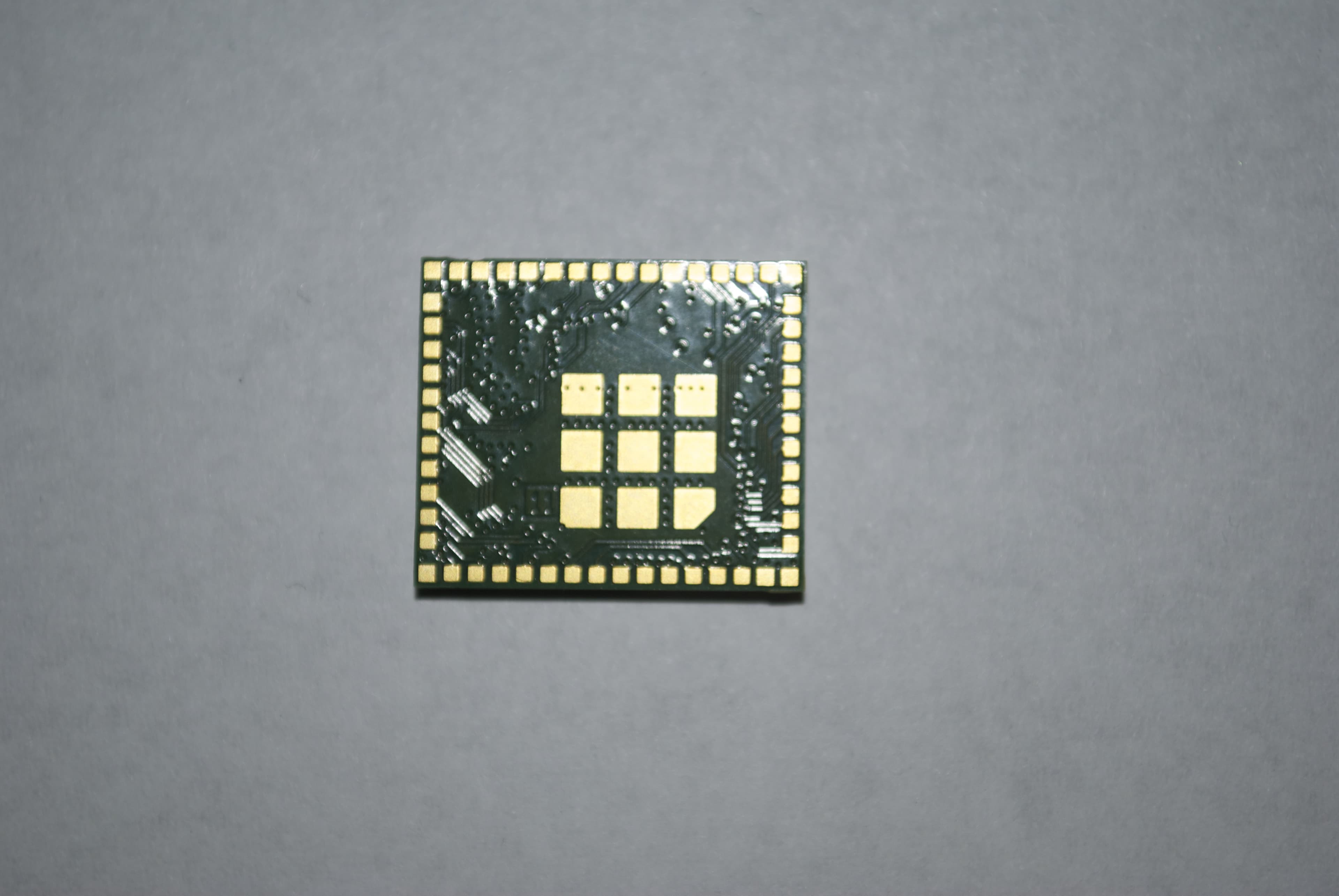
Z64-CC3200MODR1
Oct 08, 2014Radio Module
Equipment Class
DTS - Digital Transmission System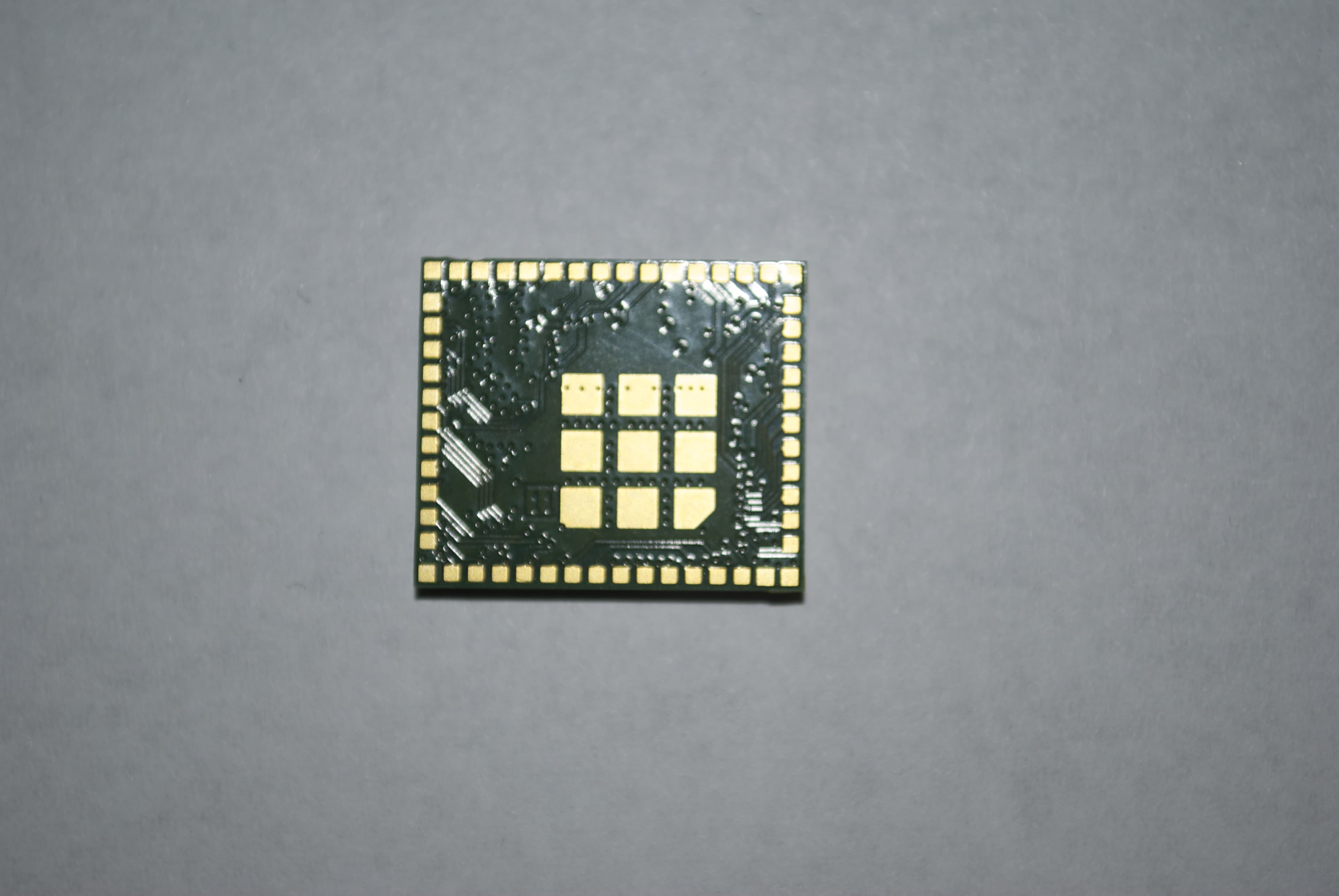
Z64-CC3100MODR1
Oct 08, 2014Radio Module
Equipment Class
DTS - Digital Transmission System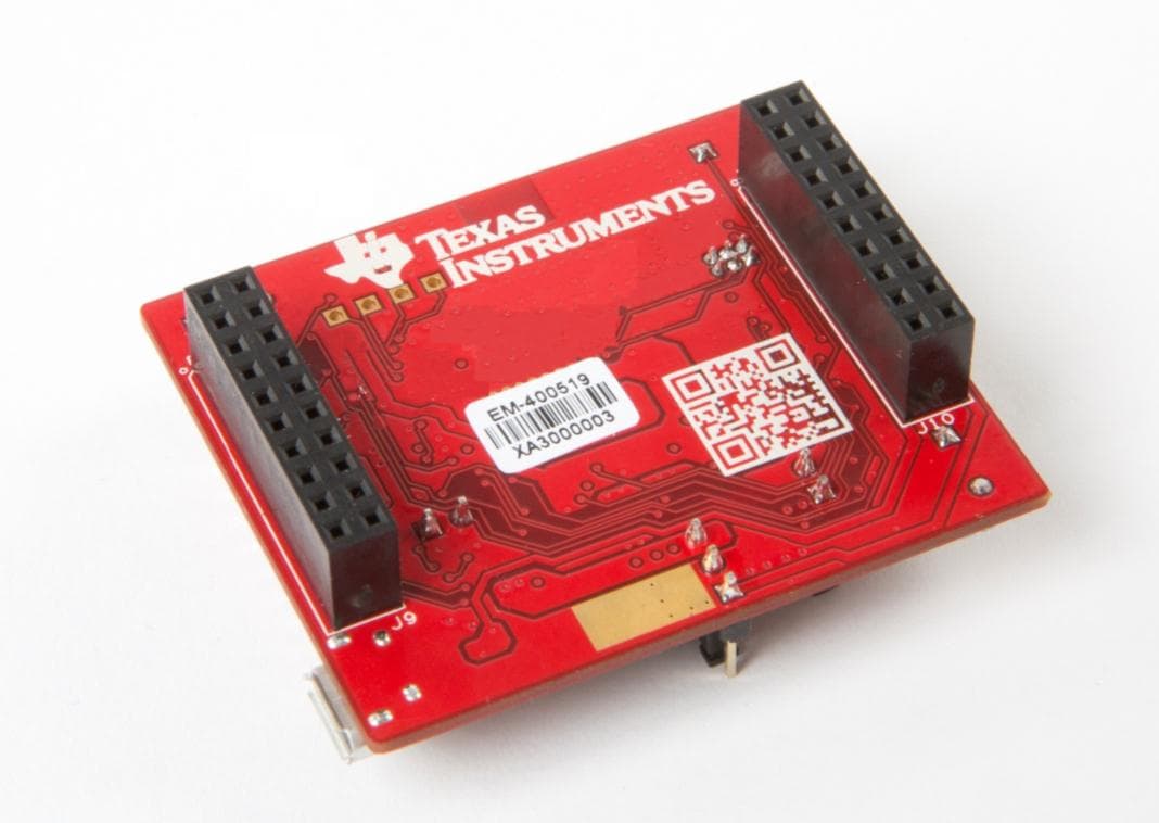
Z64-CC3100KITA
May 06, 2014Evaluation board
Equipment Class
DTS - Digital Transmission System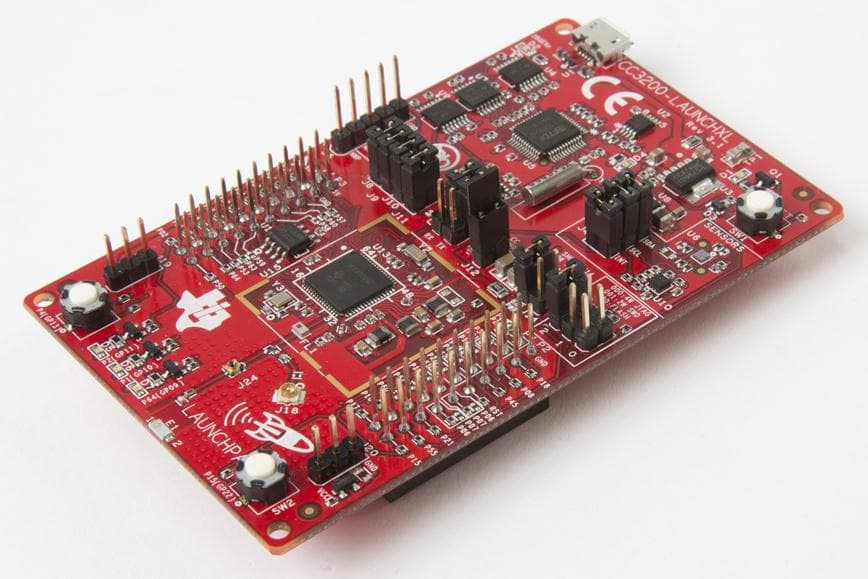
Z64-CC3200KITA
May 06, 2014Evaluation board
Equipment Class
DTS - Digital Transmission System