Z64-GASSENSOREVMGas Sensor Platform with Bluetooth Low-Energy Reference Design from Texas Instruments
Texas Instruments Incorporated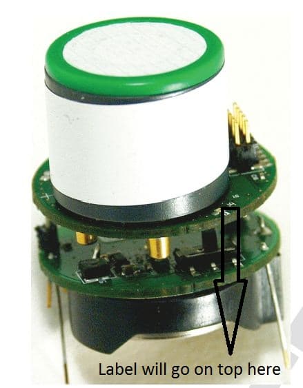
Click to zoom
Application Details
- Equipment Class
- DTS - Digital Transmission System
- Date of Grant
- Jul 04, 2013
- Application Purpose
- Original Equipment
- Date of Application
- Jul 04, 2013
- Equipment Note
- Gas Sensor Platform with Bluetooth Low-Energy Reference Design from Texas Instruments
- Frequency Range
- 2402.00000000 - 2480.00000000
- Country
- United States
Documents & Files
Document Text
Text extracted from the exhibit documents filed with the FCC. Open a document above to read the original.
Users Manual
Gas Sensor Platform Reference Design User's Guide User's Guide Literature Number: SNOA922 April 2013 WEBENCH is a registered trademark of Texas Instruments. SmartRF is a trademark of Texas instruments. iPhone, iPad, iPhone 4S, iPad 3 are registered trademarks of Apple Inc. App Store is a trademark of Apple Inc. (service mark). Embedded Workbench is a registered trademark of IAR Systems. I 2 C is a trademark of NXP. Bluetoothis a registered trademark of SIG, Inc. All other trademarks are the property of their respective owners. Contents 1Gas Sensor Platform Reference Design User's Guide..............................................................5 1.1Introduction..................................................................................................................5 1.1.1 Fundamental Blocks of LMP91000:.............................................................................7 1.1.2 Examples of Firmware and iOS Calculation....................................................................8 1.1.2.1O 2 Sensor Example.........................................................................................8 1.2CO Sensor Example........................................................................................................9 1.2.1 Postprocessing Steps as Implemented in the iOS............................................................9 1.3Supported Sensor Types..................................................................................................9 1.3.1 WEBENCH ® Support.............................................................................................11 2Features...........................................................................................................................12 2.1Gas Sensor Platform With BLE Design Features.....................................................................12 2.2Featured Applications.....................................................................................................14 2.3Highlighted Products......................................................................................................14 2.4Block Diagram.............................................................................................................15 3Hardware Description........................................................................................................16 3.1Getting Started.............................................................................................................16 3.2Battery Life Calculation...................................................................................................18 4Antenna Simulations..........................................................................................................19 4.1Simulations With the Battery Board (SAT0009).......................................................................19 4.2Summary of Findings.....................................................................................................24 4.3Conclusion..................................................................................................................24 4.4FCC Reports...............................................................................................................24 5Schematics and Bill Of Materials.........................................................................................25 5.1SAT Gas Sensor Platform With BLE....................................................................................25 5.1.1 Power Board Schematic and BOM.............................................................................25 5.2BLE and AFE Section.....................................................................................................27 6Layout..............................................................................................................................32 6.1SAT Gas Sensor Platform With BLE....................................................................................32 6.1.1 SAT0009 (Power Board) Layer Plots..........................................................................32 6.1.2 SAT0010 (AFE and BLE Board) Layer Plots.................................................................32 7Practical Applications........................................................................................................34 7.1iOS Application............................................................................................................34 7.2Firmware Section..........................................................................................................37 ASAT0009 Power Board Files................................................................................................41 A.1Gerber Files................................................................................................................41 A.2Altium Project Files........................................................................................................41 2 ContentsSNOA922 – April 2013 Submit Documentation Feedback Copyright © 2013, Texas Instruments Incorporated www.ti.com List of Figures 1-1.Sensor Design...............................................................................................................7 1-2.CO Setup.....................................................................................................................9 1-3.O 2 Setup......................................................................................................................9 1-4.3-Lead Amperometric Cell................................................................................................10 1-5.2-Lead Galvanic Cell In Potentiostat Configuration...................................................................10 1-6.WEBENCH CO............................................................................................................11 1-7.WEBENCH O 2 ....................................................…
Text truncated - open the document above for the full version.
Block Diagram
Block Diagram LMP91000 (Analog Front End for Gas Sensing) CC2541 (ADC + microcontroller, BLE Radio) LM4120 (Precision Reference) Coin Cell Battery CR2032 TPS61220 Boost Converter Block Diagram –Must include frequency at all oscillators of the rf board Block Diagram of the CC2541 (Bluetooth Low Energy Chip) RX LO = 2402 ‐ 2478 MHz VCO = 4808 ‐ 4956 MHz
Operational Description
Gas Sensor Platform with Bluetooth low- energy The Gas Sensor Platform with Bluetooth low-energy (BLE) is intended as a reference design that customers can use to develop end-products for consumer and industrial applications to monitor gases like carbon monoxide (CO), oxygen (O2), ammonia, fluorine, chlorine dioxide etc. . BLE adds a wireless feature to the platform that enables seamless connectivity to an iPhone® or an iPad®. Customers can easily replace the targeted gas sensor based on their application, while keeping the same analog frontend(AFE) and BLE design. The system runs on a CR2032 coin-cell battery. AFE from TI — LMP91000 —interfaces directly with the electrochemical cell. The LMP91000 interfaces with CC2541 which is a BLEsystem on a chip from TI. An iOS application running on an iPhone 4S® and newer generations or an iPad 3® and newer generations lets customers interface with this reference platform. Customers can use and customize the iOS application, the hardware files and firmware source code of CC2541, which TI provides as an open source. The Gas Sensor Platform with BLE provides customers with a low-power, configurable AFE and the option to integrate wireless features in gas-sensing applications. This platform helps customers access the market faster and helps differentiate from performance, power, and feature sets. The heart of this reference platform is the AFE from TI, the LMP91000. The LMP91000 is perfect for use in micropower, electrochemical-sensing applications. The LMP91000 provides a complete signal-path solution between a sensor and a microcontroller that generates an output voltage proportional to the cellcurrent. This device provides all of the functionality for detecting changes in gas concentration based on a delta current at the working electrode. Gas Sensor Platform With BLE Design Features • Coin-cell operation (CR2032) • Low-power configurable AFE (LMP91000) that provides flexibility for customers to use the same AFE for different gas-sensing platforms and configure different platforms with a simple firmware update • Provides reference design for BLE antenna design - leveraging low-cost trace antenna • Enables customers to use the platform to incorporate wireless features in gas-sensing applications • TI provides BLE firmware and iOS application software as open-source to help customers get to the market faster. • The platform is comprised of two boards that are stacked together and are referred to as SAT0009 (power board) and SAT0010 (AFE and Bluetooth board). Featured Applications The Gas Sensor Platform with BLE Reference Platform is designed to demonstrate how a configurable AFE can be used with a low-power wireless radio to provide a reference platform that will help customers develop their next-generation gas-sensing solutions for: • Industrial: gas-sensing application • Consumer: carbon monoxide-sensing application • Healthcare facilities: gas-sensing application
RF Exposure Info
Nemko Canada Inc RF Exposure Compliance (Annex C of RSS-102) Nemko Canada Inc, 303 River Road, Ottawa, Ontario, Canada, K1V 1H2 Tel: +1 (613) 737 9680, Fax: +1 (613) 737 9691 Email : [email protected] RSS 102 Annex C March 2010 Annex C – Declaration of RF Exposure Compliance for Exemption from Routine Evaluation Limits ATTESTATION: I attest that the radiocommunication apparatus meets the exemption from the routine evaluation limits in Section 2.5 of this standard; that the Technical Brief was prepared and the information contained therein is correct; that the device evaluation was performed or supervised by me; that applicable measurement methods and evaluation methodologies have been followed; and that the device meets the SAR and/or RF field strength limits of RSS-102. RSS 102, paragraph 2.5.2 RF exposure evaluation is required if the separation distance between the user and the device’s radiating element is greater than 20 cm, except when the device operates as follows: below 1.5 GHz and the maximum e.i.r.p. of the device is equal to or less than 2.5 W; at or above 1.5 GHz and the maximum e.i.r.p. of the device is equal to or less than 5 W. E.I.R.P. = Conducted rf power + antenna gain (dBi) E.I.R.P. = 0 dBm + 2.15) = +2.15 dBm E.I.R.P. = 0.0016 mW Signature: Date: 6/15/13 NAME: (Please print or type): David Light TITLE: (Please print or type): Senior Wireless Test Engineer COMPANY: (Please print or type): Nemko USA, Inc.
Schematics
1 1 2 2 3 3 4 4 5 5 6 6 DD CC BB AA DESIGNED WITH ALTIUM DESIGNER APPROVALSDATE DRAWN BY DESIGNER CHECKER ENGINEER DO NOT SCALE DRAWING SIZE FSCM NO.DRAWING NO. REV. SCALE: B SAT0009E1 Texas Instruments TPS61220 SHEET of11 R. Young 10/5/2012 ---- ---- ---- --/--/-- --/--/-- --/--/-- ---- NONE DRAWING TITLE ionDesign Incorporated 4410 Shoalwood Austin, Texas 78756 Telephone: (512)260-5778 GND GND GND GND V_COIN_CELL CR2032 COIN CELL BATTERY GNDGND VDD 12 L5 12 BT1 VDD EXPECTED 3V EN 6 GND 3 L 5 VOUT 4 FB 2 VIN 1 U3 10uF 6.3V 1 2 C22 10uF 6.3V 1 2 C23 6 6 3 3 C2 5 4 4 C1 2 1 1 U2 1M R16 200 kohm R17 0.1uF 10V 1 2 C20 12 J2 VDD GND 12 J3 1uF 6.3V 1 2 C38 1 J6 1 J8 1 J9 47uF 6.3V 1 2 C21 PIBT101PIBT102 COBT1 PIC2001 PIC2002 COC20 PIC2101 PIC2102 COC21 PIC2201 PIC2202 COC22 PIC2301 PIC2302 COC23 PIC3801 PIC3802 COC38 PIJ201PIJ202 COJ2 PIJ301PIJ302 COJ3 PIJ601 COJ6 PIJ801 COJ8 PIJ901 COJ9 PIL501PIL502 COL5 PIR1601 PIR1602 COR16 PIR1701 PIR1702 COR17 PIU201 PIU202 PIU203 PIU204 PIU205 PIU206 COU2 PIU301 PIU302 PIU303 PIU304 PIU305 PIU306 COU3 PIBT102 PIC2002PIC2102PIC2202PIC2302 PIC3802 PIJ301 PIR1701 PIU303 PIBT101 PIU201PIU204 PIJ201PIJ202 PIJ601PIJ801PIJ901 PIL501PIU305 PIR1601 PIR1702 PIU302 PIU203PIU206 PIC2001PIC2101PIC2201 PIL502 PIU202PIU205PIU301 PIU306 NLV0COIN0CELL PIC2301 PIC3801 PIJ302 PIR1602 PIU304 Bill of Materials Texas Instruments Source Data From:SAT0009 Rev E1.PrjPcb Project:SAT0009 Rev E1.PrjPcb Variant:None Creation Date: 3/6/201310:39:07 AM Print Date:4133941339.44385 FootprintCommentLibRefDesignatorDescriptionQuantity BATTHOLD- BS-7-CR2032 BS-7-NDBS-7-NDBT1BATTERY HOLDER1 C402-25RDGRM155R71A1 04KA01D GRM155R71A1 04KA01D C20CAP CER 0.1UF 10V 10% X7R1 C1206-40X70GRM31CR60J47 6KE19L GRM31CR60J47 6KE19L C21CAP CER 47uF 6.3V 10% X5R1 C603-35X45GRM188R60J10 6ME47D GRM188R60J10 6ME47D C22, C23CAP CER 10UF 6.3V 20% X5R2 C402-25RDGRM155R60J10 5KE19D GRM155R60J10 5KE19D C38CAP CER 1UF 6.3V 10% X5R1 JUMP1X2- 3826-50CTR TBSTC-501-D- 200-22-G-300- LF TBSTC-501-D- 200-22-G-300- LF J2, J3Major League Elec .050x.050 cl Thicker Brd Stacker Term Strips - Custom 2 JUMP1X1- 3826-50CTR TSW-101-07-G- S TSW-101-07-G- S J6, J8, J9CONN HEADER 1POS .100" SGL GOLD3 EPL3015- INDUCTOR EPL3015EPL3015L5Power Inductor, Shielded, 20% Tol.1 R402-25RDCRCW04021M0 0JNED CRCW04021M0 0JNED R16RES 1.0M OHM 1/16W 5%1 R402-25RDCRCW0402200 KJNED CRCW0402200 KJNED R17RES 200K OHM 1/16W 5%1 EG1390- SWITCH EG1390BEG1390BU21 DCK6TPS61220DCKTPS61220DCKU31 16 ApprovedNotes CommentDescriptionDesignatorFootprintLibRef BS-7-NDBATTERY HOLDERBT1BATTHOLD-BS-7-CR203 2BS-7-ND GRM155R71A104KA01D CAP CER 0.1UF 10V 10 %C20C402-25RDGRM155R71A104KA01D TSW-101-07-G-SCONN HEADER 1POS .1 0C21, J6, J8, J9JUMP1X1-3826-50CTRTSW-101-07-G-S GRM188R60J106ME47D CAP CER 10UF 6.3V 20 %C22, C23C603-35X45GRM188R60J106ME47D GRM155R60J105KE19D CAP CER 1UF 6.3V 10% XC38C402-25RDGRM155R60J105KE19D TBSTC-501-D-200-22-G- 3Major League Elec .050x.0J2, J3JUMP1X2-3826-50CTRTBSTC-501-D-200-22-G-3 EPL3015Power Inductor, Shielded, L5EPL3015-INDUCTOREPL3015 CRCW04021M00JNEDRES 1.0M OHM 1/16W 5 %R16R402-25RDCRCW04021M00JNED CRCW0402200KJNEDRES 200K OHM 1/16W 5 %R17R402-25RDCRCW0402200KJNED EG1390BU2EG1390-SWITCHEG1390B TPS61220DCKU3DCK6TPS61220DCK QuantityManufacturerufacturer Part NuSupplier 1pplier Part Number 1 1Digi-KeyBS-7-ND 1GRM155R71A1 0Digi-KeyGRM155R71A104KA01D-ND 4 Samtec, Inc.Digi-KeySAM1029-01-ND 2GRM188R60J1 0Digi-Key490-3896-2-ND 1GRM155R60J1 0Digi-Key490-1320-2-ND 2 MAJOR LEAGU ETBSTC-501-D-20 1 CoilcraftEPL3015-427ML 1Digi-Key541-1.0MJCT-ND 1Digi-Key541-200KJDKR-ND 1Digi-KeyEG4633TR-ND 1Digi-Key296-32505-2-ND
Test Report
Nemko Test Report: 10240453RUS1 Rev2 Applicant: Texas Instruments, Inc. 12500 TI Boulevard Dallas TX 75243 Equipment Under Test: GASSENSOREVM (E.U.T.) FCC ID#: Z64-GASSENSOREVM IC ID#: 451I- GASSENSOREV In Accordance With: FCC Part 15, Subpart C, 15.247 and Industry Canada RSS-210, Issue 8 Digital Transmission Systems Tested By: Nemko USA, Inc. 802 N. Kealy Lewisville, Texas 75057-3136 TESTED BY: DATE: 12 April 2013 David Light, Senior Wireless Engineer APPROVED BY: DATE: 14 June 2013 Mike Cantwell, Reviewer Number of Pages: 35 Nemko USA, Inc. FCC PART 15, SUBPART C and Industry Canada RSS-210, Issue 8 Digital Transmission Systems EQUIPMENT: GASSENSOREVM Test Report No.: 10240453RUS1 Page 2 of 35 Table of Contents SECTION 1. SUMMARY OF TEST RESULTS 3 SECTION 2. EQUIPMENT UNDER TEST (E.U.T.) 5 SECTION 3. OCCUPIED BANDWIDTH 7 SECTION 4. MAXIMUM PEAK OUTPUT POWER 12 SECTION 5 SPURIOUS EMISSIONS AT ANTENNA TERMINALS 16 SECTION 6. RADIATED EMISSIONS 21 SECTION 7. PEAK POWER SPECTRAL DENSITY 22 SECTION 8. TEST EQUIPMENT LIST 26 ANNEX A - TEST DETAILS 27 ANNEX B - TEST DIAGRAMS 33 Nemko USA, Inc. FCC PART 15, SUBPART C and Industry Canada RSS-210, Issue 8 Digital Transmission Systems EQUIPMENT: GASSENSOREVM Test Report No.: 10240453RUS1 Page 3 of 35 Section 1. Summary of Test Results Manufacturer: Texas Instruments, Inc. Model No.: GASSENSOREVM Serial No.: None General: All measurements are traceable to national standards. These tests were conducted on a sample of the equipment for the purpose of demonstrating compliance with Part 15, Subpart C, Paragraph 15.247 and Industry Canada RSS-210, Issue 8 for Digital Transmission Systems. Tests were conducted in accordance with ANSI C63.4-2003 and FCC KDB publication 558074 v03r01. Radiated emissions are made in a semi-anechoic chamber. A description of the test facility is on file with the FCC and Industry Canada. New Submission Production Unit Class II Permissive Change Pre-Production Unit THIS TEST REPORT RELATES ONLY TO THE ITEM(S) TESTED. THE FOLLOWING DEVIATIONS FROM, ADDITIONS TO, OR EXCLUSIONS FROM THE TEST SPECIFICATIONS HAVE BEEN MADE. See “ Summary of Test Data”. Nemko USA, Inc. authorizes the above named company to reproduce this report provided it is reproduced in its entirety, for use by the company’s employees only. This report must not be used to claim product certification, approval, or endorsement by NVLAP, NIST, or any agency of the Federal Government. Nemko USA, Inc. is a NVLAP accredited laboratory. Any use which a third party makes of this report, or any reliance on or decisions to be made based on it, are the responsibility of such third parties. Nemko USA, Inc. accepts no responsibility for damages, if any, suffered by any third party as a result of decisions made or actions based on this report. This report applies only to the items tested. Nemko USA, Inc. FCC PART 15, SUBPART C and Industry Canada RSS-210, Issue 8 Digital Transmission Systems EQUIPMENT: GASSENSOREVM Test Report No.: 10240453RUS1 Page 4 of 35 Summary Of Test Data NAME OF TEST PARA. NO. RESULT Powerline Conducted Emissions 15.207(a) / RSS-Gen 7.2.4 NA Minimum 6 dB Bandwidth 15.247(a)(2) / A8.2(a) Complies Maximum Peak Power Output 15.247(b)(3) / A8.4(4) Complies Spurious Emissions (Antenna Conducted) 15.247(d) / A8.5 Complies Spurious Emissions (Restricted Bands) 15.247(d)/15.209(a) / RSS-Gen 7.2.2 Complies Peak Power Spectral Density 15.247(e) / A8.2(b) Complies Footnotes: The EUT is battery powered. Nemko USA, Inc. FCC PART 15, SUBPART C and Industry Canada RSS-210, Issue 8 Digital Transmission Systems EQUIPMENT: GASSENSOREVM Test Report No.: 10240453RUS1 Page 5 of 35 Section 2. Equipment Under Test (E.U.T.) General Equipment Information Frequency Band (MHz): 902-928 2400-2483.5 5725-5850 Operating Frequency of Test Sample: 2402 to 2480 MHz Channel Spacing: 1 MHz User Frequency Adjustment: Software controlled Nemko USA, Inc. FCC PART 15, SUBPART C and Industry Canada RSS-210, Issue 8 Digital Transmission Systems EQUIPMENT: GASSENSOREVM Test Report No.: 10240453RUS1 Page 6 of 35 Description of EUT The system is a small, simple wireless gas sensor application. The radio is as per Bluetooth Low Energy standard communicating to an IOS or an Android device System Diagram Nemko USA, Inc. FCC PART 15, SUBPART C and Industry Canada RSS-210, Issue 8 Digital Transmission Systems EQUIPMENT: GASSENSOREVM Test Report No.: 10240453RUS1 Page 7 of 35 Section 3. Occupied Bandwidth NAME OF TEST: Occupied Bandwidth PARA. NO.: 15.247(a)(2)/A8.2(a) TESTED BY: David Light DATE: 08 February 2013 Test Results: Complies. Measurement Data: See 6 dB BW plot Measured 6 dB bandwidth: 717 kHz Channel Separation: 1 MHz Test Conditions: 45 %RH 23 °C Measurement Uncertainty: +/-1x10 -7 ppm Test Equipment Used: 1036-1082-1469 Nemko USA, Inc. FCC PART 15, SUBPART C and Industry Canada RSS-210, Issue 8 Digital Transmission Systems EQUIPMENT: GASSENSOREVM Test Report No.: 10240453RUS1 Page 8 of 35 Test Data – Occupied Bandwidth Low Channel Nemko USA, Inc. FCC PART 15, SUBPART C and Industry Canada RSS-210, Issue 8 Digital Transmission Systems EQUIPMENT: GASSENSOREVM Test Report No.: 10240453RUS1 Page 9 of 35 Test Data – Occupied Bandwidth Middle Channel Nemko USA, Inc. FCC PART 15, SUBPART C and Industry Canada RSS-210, Issue 8 Digital Transmission Systems EQUIPMENT: GASSENSOREVM Test Report No.: 10240453RUS1 Page 10 of 35 Test Data – Occupied Bandwidth High Channel Nemko USA, Inc. FCC PART 15, SUBPART C and Industry Canada RSS-210, Issue 8 Digital Transmission Systems EQUIPMENT: GASSENSOREVM Test Report No.: 10240453RUS1 Page 11 of 35 Test Data – 20 dB Bandwidth Nemko USA, Inc. FCC PART 15, SUBPART C and Industry Canada RSS-210, Issue 8 Digital Transmission Systems EQUIPMENT: GASSENSOREVM Test Report No.: 10240453RUS1 Page 12 of 35 Section 4. Maximum Peak Output Power NAME OF TEST: Maximum Peak Output power PARA. NO.: 15.247(b)(3)/A8.4(4) TESTED BY: David Light DATE: 08 April 2013 Test Results:…
Text truncated - open the document above for the full version.
Contact Information
Applicant
Marian Kost(Product Line Manager, Connectivity)
Technical Contact
Texas InstrumentsJohn Gorman
[email protected](214) 567-6695
12500 TI Boulevard, M/S 8669 · Dallas · United States
Non-Technical Contact
Nemko USA, Inc.Zarah MacIvor
[email protected]214-629-5683
Test Firm
Nemko USA, Inc.Jenny Gibbs
Technical Specifications
| # | Rule Parts | Frequency Range | Power Output |
|---|---|---|---|
| 1 | 15C | 2.40 GHz - 2.48 GHz | 1.00 mW |
Other Applications from Texas Instruments Incorporated
Z64-CC33SBMOD
Jul 17, 2025802.11 b/g/n/ax WLAN + BLE Radio Module
Equipment Class
DTS - Digital Transmission System
Z64-CC3200MODR1
Oct 08, 2014Radio Module
Equipment Class
DTS - Digital Transmission System
Z64-CC3100MODR1
Oct 08, 2014Radio Module
Equipment Class
DTS - Digital Transmission System
Z64-CC3100KITA
May 06, 2014Evaluation board
Equipment Class
DTS - Digital Transmission System
Z64-CC3200KITA
May 06, 2014Evaluation board
Equipment Class
DTS - Digital Transmission System